EP0312458A2 - Method for reducing pressure of highly compressed gases without generation of condensation droplets - Google Patents
Method for reducing pressure of highly compressed gases without generation of condensation droplets Download PDFInfo
- Publication number
- EP0312458A2 EP0312458A2 EP88402594A EP88402594A EP0312458A2 EP 0312458 A2 EP0312458 A2 EP 0312458A2 EP 88402594 A EP88402594 A EP 88402594A EP 88402594 A EP88402594 A EP 88402594A EP 0312458 A2 EP0312458 A2 EP 0312458A2
- Authority
- EP
- European Patent Office
- Prior art keywords
- pressure
- gas
- compressed gas
- critical
- orifices
- Prior art date
- Legal status (The legal status is an assumption and is not a legal conclusion. Google has not performed a legal analysis and makes no representation as to the accuracy of the status listed.)
- Granted
Links
Images

Classifications
-
- G—PHYSICS
- G01—MEASURING; TESTING
- G01N—INVESTIGATING OR ANALYSING MATERIALS BY DETERMINING THEIR CHEMICAL OR PHYSICAL PROPERTIES
- G01N9/00—Investigating density or specific gravity of materials; Analysing materials by determining density or specific gravity
-
- G—PHYSICS
- G01—MEASURING; TESTING
- G01N—INVESTIGATING OR ANALYSING MATERIALS BY DETERMINING THEIR CHEMICAL OR PHYSICAL PROPERTIES
- G01N25/00—Investigating or analyzing materials by the use of thermal means
- G01N25/14—Investigating or analyzing materials by the use of thermal means by using distillation, extraction, sublimation, condensation, freezing, or crystallisation
- G01N25/142—Investigating or analyzing materials by the use of thermal means by using distillation, extraction, sublimation, condensation, freezing, or crystallisation by condensation
-
- F—MECHANICAL ENGINEERING; LIGHTING; HEATING; WEAPONS; BLASTING
- F17—STORING OR DISTRIBUTING GASES OR LIQUIDS
- F17C—VESSELS FOR CONTAINING OR STORING COMPRESSED, LIQUEFIED OR SOLIDIFIED GASES; FIXED-CAPACITY GAS-HOLDERS; FILLING VESSELS WITH, OR DISCHARGING FROM VESSELS, COMPRESSED, LIQUEFIED, OR SOLIDIFIED GASES
- F17C7/00—Methods or apparatus for discharging liquefied, solidified, or compressed gases from pressure vessels, not covered by another subclass
-
- F—MECHANICAL ENGINEERING; LIGHTING; HEATING; WEAPONS; BLASTING
- F17—STORING OR DISTRIBUTING GASES OR LIQUIDS
- F17C—VESSELS FOR CONTAINING OR STORING COMPRESSED, LIQUEFIED OR SOLIDIFIED GASES; FIXED-CAPACITY GAS-HOLDERS; FILLING VESSELS WITH, OR DISCHARGING FROM VESSELS, COMPRESSED, LIQUEFIED, OR SOLIDIFIED GASES
- F17C2205/00—Vessel construction, in particular mounting arrangements, attachments or identifications means
- F17C2205/03—Fluid connections, filters, valves, closure means or other attachments
- F17C2205/0302—Fittings, valves, filters, or components in connection with the gas storage device
- F17C2205/0338—Pressure regulators
-
- F—MECHANICAL ENGINEERING; LIGHTING; HEATING; WEAPONS; BLASTING
- F17—STORING OR DISTRIBUTING GASES OR LIQUIDS
- F17C—VESSELS FOR CONTAINING OR STORING COMPRESSED, LIQUEFIED OR SOLIDIFIED GASES; FIXED-CAPACITY GAS-HOLDERS; FILLING VESSELS WITH, OR DISCHARGING FROM VESSELS, COMPRESSED, LIQUEFIED, OR SOLIDIFIED GASES
- F17C2205/00—Vessel construction, in particular mounting arrangements, attachments or identifications means
- F17C2205/03—Fluid connections, filters, valves, closure means or other attachments
- F17C2205/0302—Fittings, valves, filters, or components in connection with the gas storage device
- F17C2205/0341—Filters
-
- F—MECHANICAL ENGINEERING; LIGHTING; HEATING; WEAPONS; BLASTING
- F17—STORING OR DISTRIBUTING GASES OR LIQUIDS
- F17C—VESSELS FOR CONTAINING OR STORING COMPRESSED, LIQUEFIED OR SOLIDIFIED GASES; FIXED-CAPACITY GAS-HOLDERS; FILLING VESSELS WITH, OR DISCHARGING FROM VESSELS, COMPRESSED, LIQUEFIED, OR SOLIDIFIED GASES
- F17C2223/00—Handled fluid before transfer, i.e. state of fluid when stored in the vessel or before transfer from the vessel
- F17C2223/01—Handled fluid before transfer, i.e. state of fluid when stored in the vessel or before transfer from the vessel characterised by the phase
- F17C2223/0107—Single phase
- F17C2223/0123—Single phase gaseous, e.g. CNG, GNC
-
- F—MECHANICAL ENGINEERING; LIGHTING; HEATING; WEAPONS; BLASTING
- F17—STORING OR DISTRIBUTING GASES OR LIQUIDS
- F17C—VESSELS FOR CONTAINING OR STORING COMPRESSED, LIQUEFIED OR SOLIDIFIED GASES; FIXED-CAPACITY GAS-HOLDERS; FILLING VESSELS WITH, OR DISCHARGING FROM VESSELS, COMPRESSED, LIQUEFIED, OR SOLIDIFIED GASES
- F17C2250/00—Accessories; Control means; Indicating, measuring or monitoring of parameters
- F17C2250/01—Intermediate tanks
-
- F—MECHANICAL ENGINEERING; LIGHTING; HEATING; WEAPONS; BLASTING
- F17—STORING OR DISTRIBUTING GASES OR LIQUIDS
- F17C—VESSELS FOR CONTAINING OR STORING COMPRESSED, LIQUEFIED OR SOLIDIFIED GASES; FIXED-CAPACITY GAS-HOLDERS; FILLING VESSELS WITH, OR DISCHARGING FROM VESSELS, COMPRESSED, LIQUEFIED, OR SOLIDIFIED GASES
- F17C2250/00—Accessories; Control means; Indicating, measuring or monitoring of parameters
- F17C2250/06—Controlling or regulating of parameters as output values
- F17C2250/0605—Parameters
- F17C2250/0642—Composition; Humidity
- F17C2250/0647—Concentration of a product
-
- F—MECHANICAL ENGINEERING; LIGHTING; HEATING; WEAPONS; BLASTING
- F17—STORING OR DISTRIBUTING GASES OR LIQUIDS
- F17C—VESSELS FOR CONTAINING OR STORING COMPRESSED, LIQUEFIED OR SOLIDIFIED GASES; FIXED-CAPACITY GAS-HOLDERS; FILLING VESSELS WITH, OR DISCHARGING FROM VESSELS, COMPRESSED, LIQUEFIED, OR SOLIDIFIED GASES
- F17C2250/00—Accessories; Control means; Indicating, measuring or monitoring of parameters
- F17C2250/06—Controlling or regulating of parameters as output values
- F17C2250/0605—Parameters
- F17C2250/0642—Composition; Humidity
- F17C2250/0657—Humidity
-
- F—MECHANICAL ENGINEERING; LIGHTING; HEATING; WEAPONS; BLASTING
- F17—STORING OR DISTRIBUTING GASES OR LIQUIDS
- F17C—VESSELS FOR CONTAINING OR STORING COMPRESSED, LIQUEFIED OR SOLIDIFIED GASES; FIXED-CAPACITY GAS-HOLDERS; FILLING VESSELS WITH, OR DISCHARGING FROM VESSELS, COMPRESSED, LIQUEFIED, OR SOLIDIFIED GASES
- F17C2265/00—Effects achieved by gas storage or gas handling
- F17C2265/01—Purifying the fluid
- F17C2265/012—Purifying the fluid by filtering
-
- G—PHYSICS
- G01—MEASURING; TESTING
- G01N—INVESTIGATING OR ANALYSING MATERIALS BY DETERMINING THEIR CHEMICAL OR PHYSICAL PROPERTIES
- G01N1/00—Sampling; Preparing specimens for investigation
- G01N1/02—Devices for withdrawing samples
- G01N1/22—Devices for withdrawing samples in the gaseous state
-
- G—PHYSICS
- G01—MEASURING; TESTING
- G01N—INVESTIGATING OR ANALYSING MATERIALS BY DETERMINING THEIR CHEMICAL OR PHYSICAL PROPERTIES
- G01N15/00—Investigating characteristics of particles; Investigating permeability, pore-volume, or surface-area of porous materials
- G01N15/06—Investigating concentration of particle suspensions
- G01N15/065—Investigating concentration of particle suspensions using condensation nuclei counters
-
- Y—GENERAL TAGGING OF NEW TECHNOLOGICAL DEVELOPMENTS; GENERAL TAGGING OF CROSS-SECTIONAL TECHNOLOGIES SPANNING OVER SEVERAL SECTIONS OF THE IPC; TECHNICAL SUBJECTS COVERED BY FORMER USPC CROSS-REFERENCE ART COLLECTIONS [XRACs] AND DIGESTS
- Y10—TECHNICAL SUBJECTS COVERED BY FORMER USPC
- Y10S—TECHNICAL SUBJECTS COVERED BY FORMER USPC CROSS-REFERENCE ART COLLECTIONS [XRACs] AND DIGESTS
- Y10S55/00—Gas separation
- Y10S55/17—Compressed air water removal
-
- Y—GENERAL TAGGING OF NEW TECHNOLOGICAL DEVELOPMENTS; GENERAL TAGGING OF CROSS-SECTIONAL TECHNOLOGIES SPANNING OVER SEVERAL SECTIONS OF THE IPC; TECHNICAL SUBJECTS COVERED BY FORMER USPC CROSS-REFERENCE ART COLLECTIONS [XRACs] AND DIGESTS
- Y10—TECHNICAL SUBJECTS COVERED BY FORMER USPC
- Y10S—TECHNICAL SUBJECTS COVERED BY FORMER USPC CROSS-REFERENCE ART COLLECTIONS [XRACs] AND DIGESTS
- Y10S55/00—Gas separation
- Y10S55/25—Agglomerators
-
- Y—GENERAL TAGGING OF NEW TECHNOLOGICAL DEVELOPMENTS; GENERAL TAGGING OF CROSS-SECTIONAL TECHNOLOGIES SPANNING OVER SEVERAL SECTIONS OF THE IPC; TECHNICAL SUBJECTS COVERED BY FORMER USPC CROSS-REFERENCE ART COLLECTIONS [XRACs] AND DIGESTS
- Y10—TECHNICAL SUBJECTS COVERED BY FORMER USPC
- Y10T—TECHNICAL SUBJECTS COVERED BY FORMER US CLASSIFICATION
- Y10T436/00—Chemistry: analytical and immunological testing
- Y10T436/25—Chemistry: analytical and immunological testing including sample preparation
- Y10T436/25375—Liberation or purification of sample or separation of material from a sample [e.g., filtering, centrifuging, etc.]
- Y10T436/255—Liberation or purification of sample or separation of material from a sample [e.g., filtering, centrifuging, etc.] including use of a solid sorbent, semipermeable membrane, or liquid extraction
-
- Y—GENERAL TAGGING OF NEW TECHNOLOGICAL DEVELOPMENTS; GENERAL TAGGING OF CROSS-SECTIONAL TECHNOLOGIES SPANNING OVER SEVERAL SECTIONS OF THE IPC; TECHNICAL SUBJECTS COVERED BY FORMER USPC CROSS-REFERENCE ART COLLECTIONS [XRACs] AND DIGESTS
- Y10—TECHNICAL SUBJECTS COVERED BY FORMER USPC
- Y10T—TECHNICAL SUBJECTS COVERED BY FORMER US CLASSIFICATION
- Y10T436/00—Chemistry: analytical and immunological testing
- Y10T436/25—Chemistry: analytical and immunological testing including sample preparation
- Y10T436/25875—Gaseous sample or with change of physical state
Definitions
- the invention relates to a method of reducing the pressure of high pressure compressed gase without generation of droplets of condensible vapors. It also relates to a device to carry out said process.
- Various impurities may be present in a compressed gas stored in a cylinder or the like, such as particles and/or vapors of condensible materials. See for example "Particle analysis in cylinder gas" - H. Y. Wen and G. Kasper - Proceedings - Institute of Environmental Sciences - May 6, 1987.
- Particle analysis is to day commonly carried out for a plurality of purposes, usually in conjunction with contamination studies. Since most analyzers operate at ambient pressure, while gases, e.g. from cylinders, can be highly compressed (up to about 2 500 psi or more), it is necessary to expand said gases to a low pressure, generally atmospheric pressure, before said particle analysis.
- a pressure regulator which generally comprises at least one critical orifice is used for the expansion of sais compressed gas, it may thus lead to the formation of droplets which will be thereafter detected as particles by the analyzer.
- the invention aims primarily at reducing the pressure of highly compressed gases without the introduction of condensation droplets in the expanded gas.
- the invention further aims at reducing the pressure of highly compressed gas in order to analyze the particles present in said gas, without introducing additionnal particles.
- the pressure drop between the high pressure at which the compressed gas is stored in a cylinder and the low pressure, e.g. atmospheric pressure, to which it is expanded is distributed over a sufficient number of stages, each comprising a critical orifice, so as to limit the momentary temperature drop of the gas in each stage to a value which is insufficient to initiate droplet formation.
- the spacing between two successive stages is preferably sufficient to allow the gas temperature after expansion through an orifice to return to approximately its original value before said expansion through said orifice.
- a device for reducing gases from 200 bar to 1 bar in 2 stages for the purpose of particle sampling, such device having applications, among others, in pressure regulators.
- the invention aims to avoid the formation of condensate droplets by distributing the entire pressure drop over a sufficient number of steps so as to limit each individual pressure drop to a value where the local cooling in the jet is insufficient to cause droplets formation.
- the method may comprise a step of applying heat to the orifice, so as to avoid cooling of the orifice and its surroundings over long periods of operation.
- Fig.2 shows various curves of droplet concentration (counts of droplets having a diameter greater than or equal to 0.01 um) versus pressure drop. These curves were obtained in a way disclosed in the co-pending application referred to above and incorporated in the present application.
- Curves 1 and 2 represent the droplet concentration versus pressure drop for two different cylinders of nitrogen having a pressure of about 2 500 psi at the beginning.
- the gas is filtered to eliminate particles, then expanded through a critical orifice and the droplets counted by a condensation nuclei counter.
- the onset points are respectively about 450 and 550 psi. Up to this pressure drop through the critical orifice, no particle is counted. Within a variation of about 50 psi of the pressure drop, about 10 droplets were counted, to reach 100 to 1 000 droplets 50 psi higher. The onset point indicates a very important variation of the slope of the curve and thus a precise frontier.
- Curves 3 and 4 represent the same as curves 1 and 2, but with the use of purifying means such as those made of molecular sieve surrounded by dry ice or an other refrigerating agent. This purifying means creates a condensation of some vapors present in the gas which has thus a lower content of condensible vapors.
- Curves 5, 6 have been drawn with gases highly purified through more efficient purifying means than those used to draw curves 3,4.
- the onset points are thus higher (about 1 440 and 1560 psi of pressure drop) and the droplet concentration still lower.
- the method of the invention aims at expanding said gas through a critical orifice to a pressure drop lower than the onset pressure drop for concentration of that gas and repeating said expansions until the aimed low pressure, i.e. generally atmospheric pressure, is reached.
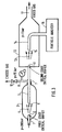
- Figure 3 shows one embodiment of the invention which can be used to reduce pressure from levels of 200 bar to 1 bar for purposes of particle sampling.
- Particle sampling is a commonly known procedure to obtain representative samples of particulate contamination from a gas by guiding a portion of said gas into an appropriate analytical device without incurring losses of particles or generating particles on the way.
- the gas from the container such as a cylinder (not represented) having a pressure of about 200 bar flows through the conduit 1 and the critical orifice 2, which may be surrounded by heating means, not represented on the figure, for the purpose of maintaining the temperature of said orifice 2 at an about constant temperature, if necessary.
- the expanded jet 4 flows in the first expansion chamber 3 having an output 7 connected to a conduit 8 and a pressure regulation valve 10, to maintain the pressure in said expansion chamber 3 above a predetermined value, e.g. 15 bar in this example (nitrogen from a cylinder has been chosen for purpose of illustration of the present invention).
- the pressure in the conduit 8 is measured by the pressure gauge 9.
- the vent valve 10 can also be a critical orifice.
- the jet 4 of gas then partially enters through the input 6 and flows through the duct 5 whose output is a second critical orifice 11 through which the gas is expanded, from an intermediate pressure (e.g. 15 bar) (between the high pressure, e.g. 200 bar and the low pressure - atmospheric pressure - 1 bar), to the low atmospheric pressure, in the second expansion chamber 12.
- the vent valve 10 (or critical orifice) allows a reduction of the volumetric gas flow rate and consequently, the gas velocity in the duct 5 approaching the next critical orifice 11. This is generally essential in this particular application of the invention to analyze particles, in order to avoid particles losses by inertial in pact as is known to be the case from the article of H.Y. Wen and G. Kasper entitled "Particle analysis in cylinder gases” published in Proceedings - Institute of Environmental Sciences (see figure 2 of this article).
- Venting gas in between stages is important because the expanding gas increased its volume flow rate and this its velocity with each expansion stage.
- the jet 13 of gas is sampled by the sensor means 14, 15 and analyzed by the particle analyzer 16. The excess of gas is vented through the output 17 of the expansion chamber 12.
- the invention thus allows, among others, to built multistage pressure regulators having a plurality of critical orifices and disposed so as to avoid sub-p.p.b. or sub-p.p.t. levels of condensible vapors to be condensed.
Abstract
Description
- The invention relates to a method of reducing the pressure of high pressure compressed gase without generation of droplets of condensible vapors. It also relates to a device to carry out said process.
- Various impurities may be present in a compressed gas stored in a cylinder or the like, such as particles and/or vapors of condensible materials. See for example "Particle analysis in cylinder gas" - H. Y. Wen and G. Kasper - Proceedings - Institute of Environmental Sciences - May 6, 1987.
- It is known from the article entitled " A gas filtration system for concentrations of 10⁻⁵ particles/cm³ " from G. KASPER and H.Y. WEN , published in Aerosol Science and Technology 5: 167 - 185 (1986), how to achieve "totally" particle-free process gases.
- Particle analysis is to day commonly carried out for a plurality of purposes, usually in conjunction with contamination studies. Since most analyzers operate at ambient pressure, while gases, e.g. from cylinders, can be highly compressed (up to about 2 500 psi or more), it is necessary to expand said gases to a low pressure, generally atmospheric pressure, before said particle analysis.
- Up to now, the measurement of said particles concentration in the gas at low pressure, e.g. atmospheric pressure, has been made by expanding said compressed gas directly from the high pressure of the cylinder to atmospheric pressure (see the first article cited above).
- However, as disclosed in the copending application, incorporated herein as a reference, entitled "Method of detecting trace amounts of condensible vapors from compressed gas" - Kasper et al. -, it has been discovered that under certain circumstances, condensible vapors, even present as trace amounts, may generate droplets of condensed vapors during the expansion of the compressed gas through a critical orifice.
- If a pressure regulator which generally comprises at least one critical orifice is used for the expansion of sais compressed gas, it may thus lead to the formation of droplets which will be thereafter detected as particles by the analyzer.
- The invention aims primarily at reducing the pressure of highly compressed gases without the introduction of condensation droplets in the expanded gas.
- The invention further aims at reducing the pressure of highly compressed gas in order to analyze the particles present in said gas, without introducing additionnal particles.
- According to the invention, the pressure drop between the high pressure at which the compressed gas is stored in a cylinder and the low pressure, e.g. atmospheric pressure, to which it is expanded, is distributed over a sufficient number of stages, each comprising a critical orifice, so as to limit the momentary temperature drop of the gas in each stage to a value which is insufficient to initiate droplet formation.
- The spacing between two successive stages is preferably sufficient to allow the gas temperature after expansion through an orifice to return to approximately its original value before said expansion through said orifice.
- One application of this method is present reduction of cylinder gases where recent experiments have shown that sub-ppb levels of hydrocarbon contamination cause droplet formation at pressure drops above about 20:1. Of course, such pressure drop may vary for different vapor impurities and/or carrier gases and have to be determined for each of them.
- One further application of this "droplet free" pressure reduction method is the analysis of particles present in the gas before pressure reduction where the formation of droplets is a disturbing artefact. Such particle analysis is today commonly carried out for a multitude of purposes usually in conjunction with contamination studies. Since most analyzers operate at ambient pressure, while gases, e.g. from cylinders, can be highly compressed, the pressure drops may be significant.
- As part of this application, a device is described for reducing gases from 200 bar to 1 bar in 2 stages for the purpose of particle sampling, such device having applications, among others, in pressure regulators.
- These and further objects will be more clearly understood by reference to the following description of various embodiments of the invention, chosen for purpose of illustration only, along with the claims and the accompanying drawings wherein :
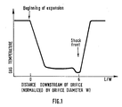
- Fig.1, represents the temperature profile of an expanding supersonic jet of gas.
- Fig. 2, shows various curves of droplets concentration versus pressure drop of gas.
- Fig. 3, shows a two-stage device used to reduce the pressure of gas from 200 bar to 1 bar without droplets formation.
- The invention aims to avoid the formation of condensate droplets by distributing the entire pressure drop over a sufficient number of steps so as to limit each individual pressure drop to a value where the local cooling in the jet is insufficient to cause droplets formation.
- To avoid droplet formation, it is necessary to provide for sufficient space between consecutive orifices, so as to allow the gas temperature to return to its original level before expansion.
- The temperature profile of an expanding supersonic jet is shown in figure 1 gas temperature versus distance L downstream of orifice, normalised by orifice diameter W. Initially there is a very rapid temperature drop associated with an almost adiabatic expansion. If the expansion were perfectly adiabatic, then the low temperature T₂ would be

T₁ = temperature of gas before expansion
P2 = pressure of gas after expansion
P1 = pressure of gas before expansion
x =
Cp = specific heat capacity of the gas at constant pressure
Cv = specific heat capacity of the gas at constant volume.
x is a well known quantity for gases (N₂ : 1.33). However, the cool jet extracts some heat from the orifice, which prevents the temperature from falling all the way. This fact is actually exploited in the present invention because otherwise it would be impossible to prevent condensation even for very slight presure drops. - About 5 to 10 orifice diameters downstream, (figure 1) the gas goes through a shock wave and then rapidly returns to roughly its original temperature as it looses its kinetic energy. (The Joule Thompson effect and heat extracted from the orifice are ignored, here).
- According to a prefered embodiment of the invention, the method may comprise a step of applying heat to the orifice, so as to avoid cooling of the orifice and its surroundings over long periods of operation.
- Fig.2 shows various curves of droplet concentration (counts of droplets having a diameter greater than or equal to 0.01 um) versus pressure drop. These curves were obtained in a way disclosed in the co-pending application referred to above and incorporated in the present application.
-
Curves 1 and 2 represent the droplet concentration versus pressure drop for two different cylinders of nitrogen having a pressure of about 2 500 psi at the beginning. The gas is filtered to eliminate particles, then expanded through a critical orifice and the droplets counted by a condensation nuclei counter. The onset points are respectively about 450 and 550 psi. Up to this pressure drop through the critical orifice, no particle is counted. Within a variation of about 50 psi of the pressure drop, about 10 droplets were counted, to reach 100 to 1 000 droplets 50 psi higher. The onset point indicates a very important variation of the slope of the curve and thus a precise frontier. -
Curves 3 and 4 represent the same ascurves 1 and 2, but with the use of purifying means such as those made of molecular sieve surrounded by dry ice or an other refrigerating agent. This purifying means creates a condensation of some vapors present in the gas which has thus a lower content of condensible vapors. - Onset points are respectively for about 890 and 990 psi of pressure drop, the droplet concentration being lower than that of
curves 1,2. -
Curves curves 3,4. The onset points are thus higher (about 1 440 and 1560 psi of pressure drop) and the droplet concentration still lower. - These various curves illustrate the phenomena on which the invention is based : as soon as the pressure drop of a gas across a critical orifice is sufficient, droplets of condensed vapors appear in the jet and may thus create a pertubation when the aim is to reduce the pressure of said gas without the formation of particles. This pressure drop depends, among others, on the initial concentration of condensible vapors in said gas.
- The method of the invention aims at expanding said gas through a critical orifice to a pressure drop lower than the onset pressure drop for concentration of that gas and repeating said expansions until the aimed low pressure, i.e. generally atmospheric pressure, is reached.
- Figure 3 shows one embodiment of the invention which can be used to reduce pressure from levels of 200 bar to 1 bar for purposes of particle sampling.
- "Particle sampling" is a commonly known procedure to obtain representative samples of particulate contamination from a gas by guiding a portion of said gas into an appropriate analytical device without incurring losses of particles or generating particles on the way.
- The gas from the container, such as a cylinder (not represented) having a pressure of about 200 bar flows through the
conduit 1 and the critical orifice 2, which may be surrounded by heating means, not represented on the figure, for the purpose of maintaining the temperature of said orifice 2 at an about constant temperature, if necessary. - The expanded
jet 4 flows in the first expansion chamber 3 having an output 7 connected to a conduit 8 and apressure regulation valve 10, to maintain the pressure in said expansion chamber 3 above a predetermined value, e.g. 15 bar in this example (nitrogen from a cylinder has been chosen for purpose of illustration of the present invention). The pressure in the conduit 8 is measured by thepressure gauge 9. Thevent valve 10 can also be a critical orifice. Thejet 4 of gas then partially enters through theinput 6 and flows through theduct 5 whose output is a secondcritical orifice 11 through which the gas is expanded, from an intermediate pressure (e.g. 15 bar) (between the high pressure, e.g. 200 bar and the low pressure - atmospheric pressure - 1 bar), to the low atmospheric pressure, in thesecond expansion chamber 12. The vent valve 10 (or critical orifice) allows a reduction of the volumetric gas flow rate and consequently, the gas velocity in theduct 5 approaching the nextcritical orifice 11. This is generally essential in this particular application of the invention to analyze particles, in order to avoid particles losses by inertial in pact as is known to be the case from the article of H.Y. Wen and G. Kasper entitled "Particle analysis in cylinder gases" published in Proceedings - Institute of Environmental Sciences (see figure 2 of this article). - Venting gas in between stages is important because the expanding gas increased its volume flow rate and this its velocity with each expansion stage.The
jet 13 of gas is sampled by the sensor means 14, 15 and analyzed by theparticle analyzer 16. The excess of gas is vented through theoutput 17 of theexpansion chamber 12. - The principles set forth above are also applicable to pressure regulating devices commonly used in the gas industry. These devices function on the basis of one or two stage variable critical orifices and suffer from essentially the same problem as simple critical orifices discussed so far. Figure 1 of the article "Particle analysis in cylinder gases" shows the significant generation of ultrafine particles (<0.1µm) and the abrupt end of this below a critical pressure drop.
- At the time this article has been published, May 6, 1987 no explanation has been given to this phenoma : the inventors had not yet proved that there is an onset pressure drop point across a critical orifice, above which condensible vapors are condensed if supersaturation may thus be created, and that the particles so detected (on figure 1 of said article) were both particles and condensed droplets.
- The invention thus allows, among others, to built multistage pressure regulators having a plurality of critical orifices and disposed so as to avoid sub-p.p.b. or sub-p.p.t. levels of condensible vapors to be condensed.
Claims (8)
Priority Applications (1)
| Application Number | Priority Date | Filing Date | Title |
|---|---|---|---|
| AT88402594T ATE71704T1 (en) | 1987-10-13 | 1988-10-13 | METHOD OF REDUCING THE PRESSURE OF A VERY COMPRESSED GAS WITHOUT CREATING COMPRESSION. |
Applications Claiming Priority (2)
| Application Number | Priority Date | Filing Date | Title |
|---|---|---|---|
| US07/107,177 US5027642A (en) | 1987-10-13 | 1987-10-13 | Method of detecting and or removing trace amounts of condensible vapors from compressed gas |
| US107177 | 1987-10-13 |
Publications (3)
| Publication Number | Publication Date |
|---|---|
| EP0312458A2 true EP0312458A2 (en) | 1989-04-19 |
| EP0312458A3 EP0312458A3 (en) | 1989-10-25 |
| EP0312458B1 EP0312458B1 (en) | 1992-01-15 |
Family
ID=22315246
Family Applications (2)
| Application Number | Title | Priority Date | Filing Date |
|---|---|---|---|
| EP88402594A Expired - Lifetime EP0312458B1 (en) | 1987-10-13 | 1988-10-13 | Method for reducing pressure of highly compressed gases without generation of condensation droplets |
| EP88402593A Expired - Lifetime EP0312457B1 (en) | 1987-10-13 | 1988-10-13 | Method of detecting trace amounts of condensible vapors from compressed gas |
Family Applications After (1)
| Application Number | Title | Priority Date | Filing Date |
|---|---|---|---|
| EP88402593A Expired - Lifetime EP0312457B1 (en) | 1987-10-13 | 1988-10-13 | Method of detecting trace amounts of condensible vapors from compressed gas |
Country Status (10)
| Country | Link |
|---|---|
| US (1) | US5027642A (en) |
| EP (2) | EP0312458B1 (en) |
| JP (1) | JP2680856B2 (en) |
| KR (1) | KR890007068A (en) |
| AT (2) | ATE106561T1 (en) |
| CA (1) | CA1325373C (en) |
| DE (2) | DE3889840T2 (en) |
| ES (1) | ES2053786T3 (en) |
| FI (1) | FI884705A (en) |
| NO (1) | NO884553L (en) |
Cited By (2)
| Publication number | Priority date | Publication date | Assignee | Title |
|---|---|---|---|---|
| EP0557150A1 (en) * | 1992-01-31 | 1993-08-25 | L'air Liquide, Societe Anonyme Pour L'etude Et L'exploitation Des Procedes Georges Claude | Method of introducing and controlling compressed gases for impurity analysis |
| WO2017125548A1 (en) * | 2016-01-21 | 2017-07-27 | Avl List Gmbh | Measurement gas extraction device |
Families Citing this family (36)
| Publication number | Priority date | Publication date | Assignee | Title |
|---|---|---|---|---|
| US4964278A (en) * | 1989-03-06 | 1990-10-23 | American Air Liquide | Method of separating condensible vapors from particles in highly compressed gases |
| US5271232A (en) * | 1990-07-20 | 1993-12-21 | Toshiba Ceramics Co., Ltd. | Filtration apparatus |
| US5583282A (en) * | 1990-12-14 | 1996-12-10 | Millipore Investment Holdings Limited | Differential gas sensing in-line monitoring system |
| US5138869A (en) * | 1990-12-14 | 1992-08-18 | Novapure Corporation | In-line detector system for real-time determination of impurity concentration in a flowing gas stream |
| US5391361A (en) * | 1991-01-23 | 1995-02-21 | Mdt Corporation | Condensate separator |
| DE4212367C2 (en) * | 1991-04-15 | 2000-08-03 | Denso Corp | Device for removing water in a cooling system |
| US5426944A (en) * | 1993-08-31 | 1995-06-27 | American Air Liquide, Inc. | Chemical purification for semiconductor processing by partial condensation |
| US5665902A (en) * | 1994-05-10 | 1997-09-09 | American Air Liquide, Inc. | Method to analyze particle contaminants in compressed gases |
| US5730181A (en) * | 1994-07-15 | 1998-03-24 | Unit Instruments, Inc. | Mass flow controller with vertical purifier |
| US5578746A (en) * | 1995-06-28 | 1996-11-26 | Motorola, Inc. | Apparatus for chemical vapor deposition and method of use |
| US5814741A (en) * | 1996-03-01 | 1998-09-29 | American Air Liquide Inc. | Metal sampling method and system for non-hydrolyzable gases |
| US5871813A (en) * | 1997-03-05 | 1999-02-16 | Applied Materials, Inc. | Apparatus and method for controlling process chamber pressure |
| US6207460B1 (en) | 1999-01-14 | 2001-03-27 | Extraction Systems, Inc. | Detection of base contaminants in gas samples |
| US6205842B1 (en) * | 1999-02-02 | 2001-03-27 | Rupprecht & Patashnick Company, Inc. | Differential particulate mass monitor with intrinsic correction for volatilization losses |
| US6502450B1 (en) | 1999-05-10 | 2003-01-07 | Rupprecht & Patashnik Company, Inc. | Single detector differential particulate mass monitor with intrinsic correction for volatilization losses |
| FR2803772B1 (en) * | 2000-01-18 | 2002-06-28 | Air Liquide | INSTALLATION FOR DISTRIBUTING AN ULTRA PURE GAS COMPRISING A PURIFICATION UNIT |
| US7064834B2 (en) * | 2002-01-22 | 2006-06-20 | Praxair Technology, Inc. | Method for analyzing impurities in carbon dioxide |
| CN1756945A (en) * | 2003-02-21 | 2006-04-05 | 密科理股份有限公司 | Method for analysis of contaminants in a process fluid stream |
| JP4559799B2 (en) * | 2004-02-26 | 2010-10-13 | ジーエルサイエンス株式会社 | Sorting method, sorting device, and liquefaction determination device |
| BRPI0512224A (en) * | 2004-06-18 | 2008-02-19 | Boc Group Inc | stored gas filtration device |
| US7343781B2 (en) * | 2005-10-13 | 2008-03-18 | Air Products And Chemicals, Inc. | Systems and methods for detecting liquid particles in a gas system |
| US7481095B2 (en) | 2005-10-13 | 2009-01-27 | Air Products And Chemicals, Inc. | Liquid particle mass measurement in gas streams |
| DE102006036785A1 (en) * | 2006-08-07 | 2008-02-14 | Robert Bosch Gmbh | Process for detecting contaminants in a gas tank |
| JP4973937B2 (en) * | 2007-08-24 | 2012-07-11 | オルガノ株式会社 | Fine particle measurement system and fine particle measurement method in high pressure fluid |
| JP5299241B2 (en) * | 2008-11-28 | 2013-09-25 | 株式会社島津製作所 | Particle counter |
| US8262866B2 (en) * | 2009-04-09 | 2012-09-11 | General Synfuels International, Inc. | Apparatus for the recovery of hydrocarbonaceous and additional products from oil shale and sands via multi-stage condensation |
| AU2015200692B2 (en) * | 2009-04-28 | 2016-05-26 | Carlisle Fluid Technologies, Inc. | Fluid through needle for applying multiple component material |
| US8388746B2 (en) * | 2010-09-23 | 2013-03-05 | Warr-2-Bros, LLC | Filtration system for a compressor station |
| FR3026185B1 (en) * | 2014-09-18 | 2017-09-29 | Commissariat Energie Atomique | SYSTEM AND METHOD FOR PARTICLE DETECTION |
| CN104406826B (en) * | 2014-11-30 | 2017-10-13 | 深圳睿境环保科技有限公司 | The method of sampling of condensable particle sampling device |
| CN105784941B (en) * | 2016-03-23 | 2017-12-26 | 中国科学院光电研究院 | A kind of online gas analyzing apparatus and method |
| CN105954068B (en) * | 2016-05-03 | 2018-11-16 | 国网山东省电力公司青州市供电公司 | Nitrogen cylinder sampler |
| DE102016112888A1 (en) * | 2016-07-13 | 2018-01-18 | Truma Gerätetechnik GmbH & Co. KG | LNG plant |
| CN106198886B (en) * | 2016-08-16 | 2018-08-28 | 中为(上海)能源技术有限公司 | Gas on-line analysis system and operating method for coal underground gasifying technology |
| US10809165B2 (en) | 2018-06-29 | 2020-10-20 | General Electric Company | Pressure reduction system and method for reducing the pressure of high pressure aerosols |
| DE102020001077A1 (en) | 2020-02-19 | 2021-08-19 | Bauer Kompressoren Gmbh | Analysis device for gases in a pressurized gas storage tank |
Citations (4)
| Publication number | Priority date | Publication date | Assignee | Title |
|---|---|---|---|---|
| FR6422E (en) * | 1906-11-17 | Veuve Elworthy Nee Ellen Gertrude Cooper | Hydrogen manufacturing | |
| BE719611A (en) * | 1967-08-17 | 1969-02-03 | ||
| US4057964A (en) * | 1975-04-07 | 1977-11-15 | Geothermal Investment Co. | Working fluids and systems for recovering geothermal or waste heat |
| EP0014396A1 (en) * | 1979-02-03 | 1980-08-20 | Mahlo GmbH & Co. KG | Method and apparatus for measuring, in a process, a gaseous component in a mixture of gases |
Family Cites Families (8)
| Publication number | Priority date | Publication date | Assignee | Title |
|---|---|---|---|---|
| DE330151C (en) * | 1916-12-18 | 1920-12-11 | George Constantinesco | Device for feeding fluid lines in which pressure waves are carried away |
| US1697344A (en) * | 1926-07-06 | 1929-01-01 | Campbell Engineering Company | Measurement and regulation of flow of steam or other fluid |
| BE539578A (en) * | 1955-10-05 | |||
| US3037421A (en) * | 1956-07-27 | 1962-06-05 | Gen Electric | Condensation nuclei detector |
| US3102192A (en) * | 1960-09-30 | 1963-08-27 | Gen Electric | Method and apparatus for detecting organic vapors and gases |
| US4272499A (en) * | 1979-11-28 | 1981-06-09 | Lone Star Steel Company | Process and apparatus for the removal of particulate matter and reactive or water soluble gases from carrier gases |
| US4358302A (en) * | 1980-11-24 | 1982-11-09 | The University Of Rochester | Apparatus for separation of gas borne particles |
| US4878510A (en) * | 1987-10-13 | 1989-11-07 | American Air Liquide | Method for reducing pressure of highly compressed gases without generation of condensation droplets |
-
1987
- 1987-10-13 US US07/107,177 patent/US5027642A/en not_active Expired - Fee Related
-
1988
- 1988-10-12 FI FI884705A patent/FI884705A/en not_active IP Right Cessation
- 1988-10-13 KR KR1019880013362A patent/KR890007068A/en not_active Application Discontinuation
- 1988-10-13 AT AT88402593T patent/ATE106561T1/en not_active IP Right Cessation
- 1988-10-13 CA CA000580013A patent/CA1325373C/en not_active Expired - Fee Related
- 1988-10-13 NO NO88884553A patent/NO884553L/en unknown
- 1988-10-13 AT AT88402594T patent/ATE71704T1/en not_active IP Right Cessation
- 1988-10-13 EP EP88402594A patent/EP0312458B1/en not_active Expired - Lifetime
- 1988-10-13 EP EP88402593A patent/EP0312457B1/en not_active Expired - Lifetime
- 1988-10-13 DE DE3889840T patent/DE3889840T2/en not_active Expired - Fee Related
- 1988-10-13 JP JP63258355A patent/JP2680856B2/en not_active Expired - Lifetime
- 1988-10-13 DE DE8888402594T patent/DE3867794D1/en not_active Expired - Lifetime
- 1988-10-13 ES ES88402593T patent/ES2053786T3/en not_active Expired - Lifetime
Patent Citations (4)
| Publication number | Priority date | Publication date | Assignee | Title |
|---|---|---|---|---|
| FR6422E (en) * | 1906-11-17 | Veuve Elworthy Nee Ellen Gertrude Cooper | Hydrogen manufacturing | |
| BE719611A (en) * | 1967-08-17 | 1969-02-03 | ||
| US4057964A (en) * | 1975-04-07 | 1977-11-15 | Geothermal Investment Co. | Working fluids and systems for recovering geothermal or waste heat |
| EP0014396A1 (en) * | 1979-02-03 | 1980-08-20 | Mahlo GmbH & Co. KG | Method and apparatus for measuring, in a process, a gaseous component in a mixture of gases |
Non-Patent Citations (4)
| Title |
|---|
| PATENT ABSTRACTS OF JAPAN * |
| PATENT ABSTRACTS OF JAPAN, vol. 6, no. 252 (P-161)(1130) 10 December 1982 * |
| PROCEEDINGS OF THE INSTITUTE OF ENVIRONMENTAL SCIENCES * |
| PROCEEDINGS OF THE INSTITUTE OF ENVIRONMENTAL SCIENCES, 6 May 1987, pages 400-402 * |
Cited By (4)
| Publication number | Priority date | Publication date | Assignee | Title |
|---|---|---|---|---|
| EP0557150A1 (en) * | 1992-01-31 | 1993-08-25 | L'air Liquide, Societe Anonyme Pour L'etude Et L'exploitation Des Procedes Georges Claude | Method of introducing and controlling compressed gases for impurity analysis |
| WO2017125548A1 (en) * | 2016-01-21 | 2017-07-27 | Avl List Gmbh | Measurement gas extraction device |
| AT518184B1 (en) * | 2016-01-21 | 2017-08-15 | Avl List Gmbh | Sample gas removal device |
| AT518184A4 (en) * | 2016-01-21 | 2017-08-15 | Avl List Gmbh | Sample gas removal device |
Also Published As
| Publication number | Publication date |
|---|---|
| ATE106561T1 (en) | 1994-06-15 |
| US5027642A (en) | 1991-07-02 |
| JPH01237434A (en) | 1989-09-21 |
| FI884705A0 (en) | 1988-10-12 |
| EP0312457B1 (en) | 1994-06-01 |
| ATE71704T1 (en) | 1992-02-15 |
| DE3889840T2 (en) | 1994-09-08 |
| EP0312457A3 (en) | 1989-10-25 |
| EP0312458A3 (en) | 1989-10-25 |
| ES2053786T3 (en) | 1994-08-01 |
| EP0312458B1 (en) | 1992-01-15 |
| DE3889840D1 (en) | 1994-07-07 |
| NO884553D0 (en) | 1988-10-13 |
| KR890007068A (en) | 1989-06-17 |
| NO884553L (en) | 1989-04-14 |
| CA1325373C (en) | 1993-12-21 |
| EP0312457A2 (en) | 1989-04-19 |
| FI884705A (en) | 1989-04-14 |
| DE3867794D1 (en) | 1992-02-27 |
| JP2680856B2 (en) | 1997-11-19 |
Similar Documents
| Publication | Publication Date | Title |
|---|---|---|
| EP0312458B1 (en) | Method for reducing pressure of highly compressed gases without generation of condensation droplets | |
| US4883958A (en) | Interface for coupling liquid chromatography to solid or gas phase detectors | |
| US5992216A (en) | Method to analyze particle contaminants in compressed gases | |
| Thiemens et al. | Oxygen isotope fractionation in stratospheric CO2 | |
| Schueler et al. | Measurement of isotopic abundances in collected stratospheric ozone samples | |
| Thiemens et al. | New experimental evidence for the mechanism for production of isotopically heavy O3 | |
| EP0370151A1 (en) | Process for producing low-concentration gas mixtures, and apparatus for producing the same | |
| US4878510A (en) | Method for reducing pressure of highly compressed gases without generation of condensation droplets | |
| US4964278A (en) | Method of separating condensible vapors from particles in highly compressed gases | |
| KR930016771A (en) | Compressed gas introduction and control method for impurity analysis | |
| Wollnik et al. | The improvement of a gas-jet system by the use of an aerosol generator | |
| WO1999063337A1 (en) | A method and apparatus for selectively extracting and compressing trace samples from a carrier to enhance detection | |
| Neuman et al. | A fast-response chemical ionization mass spectrometer for in situ measurements of HNO3 in the upper troposphere and lower stratosphere | |
| Overcamp et al. | Effect of Reynolds number on the Stokes number of cyclones | |
| de la Mora et al. | Performance of a hypersonic impactor with silver particles in the 2 nm range | |
| US2775707A (en) | Heat compensating device | |
| Prosser et al. | A preliminary investigation into the isotopic measurement of carbon at the picomole level using static vacuum mass spectrometry | |
| Zhang et al. | Determination of particle vapor pressures using the tandem differential mobility analyzer | |
| Hoffman et al. | Pioneer Venus large probe neutral mass spectrometer | |
| EP0370870A1 (en) | Process for producing low-concentration gas mixtures, and apparatus for producing the same | |
| Salcedo et al. | Effect of relative humidity on the detection of sulfur dioxide and sulfuric acid using a chemical ionization mass spectrometer | |
| Sansone et al. | A note on the penetration of a circular tube by an aerosol with a log-normal size distribution | |
| Martell | High altitude air sampling with a rocketborne cryocondenser | |
| HU215985B (en) | Device for watching atmosphere inside the safety tank of a reactor | |
| Kuga et al. | Improvement of multi jet low pressure impactor for high collection efficiency of UF5 in the molecular laser isotope separation of uranium |
Legal Events
| Date | Code | Title | Description |
|---|---|---|---|
| PUAI | Public reference made under article 153(3) epc to a published international application that has entered the european phase |
Free format text: ORIGINAL CODE: 0009012 |
|
| 17P | Request for examination filed |
Effective date: 19881017 |
|
| AK | Designated contracting states |
Kind code of ref document: A2 Designated state(s): AT BE CH DE ES FR GB IT LI NL SE |
|
| PUAL | Search report despatched |
Free format text: ORIGINAL CODE: 0009013 |
|
| AK | Designated contracting states |
Kind code of ref document: A3 Designated state(s): AT BE CH DE ES FR GB IT LI NL SE |
|
| RHK1 | Main classification (correction) |
Ipc: F17C 7/00 |
|
| 17Q | First examination report despatched |
Effective date: 19910618 |
|
| GRAA | (expected) grant |
Free format text: ORIGINAL CODE: 0009210 |
|
| ITF | It: translation for a ep patent filed |
Owner name: BARZANO' E ZANARDO MILANO S.P.A. |
|
| AK | Designated contracting states |
Kind code of ref document: B1 Designated state(s): AT BE CH DE ES FR GB IT LI NL SE |
|
| PG25 | Lapsed in a contracting state [announced via postgrant information from national office to epo] |
Ref country code: ES Free format text: THE PATENT HAS BEEN ANNULLED BY A DECISION OF A NATIONAL AUTHORITY Effective date: 19920115 Ref country code: BE Effective date: 19920115 Ref country code: AT Effective date: 19920115 |
|
| REF | Corresponds to: |
Ref document number: 71704 Country of ref document: AT Date of ref document: 19920215 Kind code of ref document: T |
|
| ET | Fr: translation filed | ||
| REF | Corresponds to: |
Ref document number: 3867794 Country of ref document: DE Date of ref document: 19920227 |
|
| PGFP | Annual fee paid to national office [announced via postgrant information from national office to epo] |
Ref country code: CH Payment date: 19920915 Year of fee payment: 5 |
|
| PLBE | No opposition filed within time limit |
Free format text: ORIGINAL CODE: 0009261 |
|
| STAA | Information on the status of an ep patent application or granted ep patent |
Free format text: STATUS: NO OPPOSITION FILED WITHIN TIME LIMIT |
|
| 26N | No opposition filed | ||
| PG25 | Lapsed in a contracting state [announced via postgrant information from national office to epo] |
Ref country code: LI Effective date: 19931031 Ref country code: CH Effective date: 19931031 |
|
| REG | Reference to a national code |
Ref country code: CH Ref legal event code: PL |
|
| EAL | Se: european patent in force in sweden |
Ref document number: 88402594.1 |
|
| PGFP | Annual fee paid to national office [announced via postgrant information from national office to epo] |
Ref country code: FR Payment date: 19960911 Year of fee payment: 9 |
|
| PGFP | Annual fee paid to national office [announced via postgrant information from national office to epo] |
Ref country code: GB Payment date: 19960920 Year of fee payment: 9 |
|
| PGFP | Annual fee paid to national office [announced via postgrant information from national office to epo] |
Ref country code: DE Payment date: 19960923 Year of fee payment: 9 |
|
| PGFP | Annual fee paid to national office [announced via postgrant information from national office to epo] |
Ref country code: SE Payment date: 19960924 Year of fee payment: 9 |
|
| PGFP | Annual fee paid to national office [announced via postgrant information from national office to epo] |
Ref country code: NL Payment date: 19960926 Year of fee payment: 9 |
|
| PG25 | Lapsed in a contracting state [announced via postgrant information from national office to epo] |
Ref country code: GB Free format text: LAPSE BECAUSE OF NON-PAYMENT OF DUE FEES Effective date: 19971013 |
|
| PG25 | Lapsed in a contracting state [announced via postgrant information from national office to epo] |
Ref country code: SE Free format text: LAPSE BECAUSE OF NON-PAYMENT OF DUE FEES Effective date: 19971014 |
|
| PG25 | Lapsed in a contracting state [announced via postgrant information from national office to epo] |
Ref country code: FR Free format text: THE PATENT HAS BEEN ANNULLED BY A DECISION OF A NATIONAL AUTHORITY Effective date: 19971031 |
|
| PG25 | Lapsed in a contracting state [announced via postgrant information from national office to epo] |
Ref country code: NL Free format text: LAPSE BECAUSE OF NON-PAYMENT OF DUE FEES Effective date: 19980501 |
|
| GBPC | Gb: european patent ceased through non-payment of renewal fee |
Effective date: 19971013 |
|
| NLV4 | Nl: lapsed or anulled due to non-payment of the annual fee |
Effective date: 19980501 |
|
| PG25 | Lapsed in a contracting state [announced via postgrant information from national office to epo] |
Ref country code: DE Free format text: LAPSE BECAUSE OF NON-PAYMENT OF DUE FEES Effective date: 19980701 |
|
| EUG | Se: european patent has lapsed |
Ref document number: 88402594.1 |
|
| REG | Reference to a national code |
Ref country code: FR Ref legal event code: ST |
|
| PG25 | Lapsed in a contracting state [announced via postgrant information from national office to epo] |
Ref country code: IT Free format text: LAPSE BECAUSE OF NON-PAYMENT OF DUE FEES;WARNING: LAPSES OF ITALIAN PATENTS WITH EFFECTIVE DATE BEFORE 2007 MAY HAVE OCCURRED AT ANY TIME BEFORE 2007. THE CORRECT EFFECTIVE DATE MAY BE DIFFERENT FROM THE ONE RECORDED. Effective date: 20051013 |