EP0312384A2 - Piezo-electric acceleration sensor - Google Patents
Piezo-electric acceleration sensor Download PDFInfo
- Publication number
- EP0312384A2 EP0312384A2 EP88309644A EP88309644A EP0312384A2 EP 0312384 A2 EP0312384 A2 EP 0312384A2 EP 88309644 A EP88309644 A EP 88309644A EP 88309644 A EP88309644 A EP 88309644A EP 0312384 A2 EP0312384 A2 EP 0312384A2
- Authority
- EP
- European Patent Office
- Prior art keywords
- hole
- piezo
- sample
- electric
- laminate
- Prior art date
- Legal status (The legal status is an assumption and is not a legal conclusion. Google has not performed a legal analysis and makes no representation as to the accuracy of the status listed.)
- Granted
Links
- 230000001133 acceleration Effects 0.000 title claims abstract description 117
- 239000012528 membrane Substances 0.000 claims abstract description 11
- 230000005611 electricity Effects 0.000 claims abstract description 3
- 229920005597 polymer membrane Polymers 0.000 claims abstract description 3
- 230000002093 peripheral effect Effects 0.000 claims description 29
- 230000007246 mechanism Effects 0.000 abstract description 3
- 101100400378 Mus musculus Marveld2 gene Proteins 0.000 abstract 1
- 230000010355 oscillation Effects 0.000 description 142
- 239000010408 film Substances 0.000 description 107
- PXHVJJICTQNCMI-UHFFFAOYSA-N Nickel Chemical compound [Ni] PXHVJJICTQNCMI-UHFFFAOYSA-N 0.000 description 53
- 230000001747 exhibiting effect Effects 0.000 description 51
- 238000001514 detection method Methods 0.000 description 45
- 229920002981 polyvinylidene fluoride Polymers 0.000 description 32
- 239000002033 PVDF binder Substances 0.000 description 28
- 239000004020 conductor Substances 0.000 description 23
- -1 poly(vinyl fluoride) Polymers 0.000 description 17
- 229910052759 nickel Inorganic materials 0.000 description 16
- 239000000463 material Substances 0.000 description 13
- 238000007740 vapor deposition Methods 0.000 description 13
- 238000000034 method Methods 0.000 description 12
- 229920000642 polymer Polymers 0.000 description 10
- 230000035945 sensitivity Effects 0.000 description 10
- 239000000853 adhesive Substances 0.000 description 9
- 230000001070 adhesive effect Effects 0.000 description 9
- 230000005484 gravity Effects 0.000 description 8
- 230000004888 barrier function Effects 0.000 description 7
- 230000000052 comparative effect Effects 0.000 description 7
- XEEYBQQBJWHFJM-UHFFFAOYSA-N Iron Chemical compound [Fe] XEEYBQQBJWHFJM-UHFFFAOYSA-N 0.000 description 6
- 229910052751 metal Inorganic materials 0.000 description 6
- 239000002184 metal Substances 0.000 description 6
- 238000007747 plating Methods 0.000 description 6
- 239000010949 copper Substances 0.000 description 5
- 239000003822 epoxy resin Substances 0.000 description 5
- 229920000647 polyepoxide Polymers 0.000 description 5
- RYGMFSIKBFXOCR-UHFFFAOYSA-N Copper Chemical compound [Cu] RYGMFSIKBFXOCR-UHFFFAOYSA-N 0.000 description 4
- 229910003460 diamond Inorganic materials 0.000 description 4
- 239000010432 diamond Substances 0.000 description 4
- 238000009713 electroplating Methods 0.000 description 4
- 241001060350 Acalypha Species 0.000 description 3
- 229910045601 alloy Inorganic materials 0.000 description 3
- 239000000956 alloy Substances 0.000 description 3
- 230000008859 change Effects 0.000 description 3
- 229920001577 copolymer Polymers 0.000 description 3
- 229910052802 copper Inorganic materials 0.000 description 3
- 230000000694 effects Effects 0.000 description 3
- 239000002305 electric material Substances 0.000 description 3
- 238000010438 heat treatment Methods 0.000 description 3
- 238000009863 impact test Methods 0.000 description 3
- 229910052742 iron Inorganic materials 0.000 description 3
- 230000004048 modification Effects 0.000 description 3
- 238000012986 modification Methods 0.000 description 3
- 229920005989 resin Polymers 0.000 description 3
- 239000011347 resin Substances 0.000 description 3
- 239000010935 stainless steel Substances 0.000 description 3
- 229910001220 stainless steel Inorganic materials 0.000 description 3
- 229910001369 Brass Inorganic materials 0.000 description 2
- KRHYYFGTRYWZRS-UHFFFAOYSA-M Fluoride anion Chemical compound [F-] KRHYYFGTRYWZRS-UHFFFAOYSA-M 0.000 description 2
- 239000010951 brass Substances 0.000 description 2
- 238000006243 chemical reaction Methods 0.000 description 2
- 230000002542 deteriorative effect Effects 0.000 description 2
- 239000003365 glass fiber Substances 0.000 description 2
- PCHJSUWPFVWCPO-UHFFFAOYSA-N gold Chemical compound [Au] PCHJSUWPFVWCPO-UHFFFAOYSA-N 0.000 description 2
- 229910052737 gold Inorganic materials 0.000 description 2
- 239000010931 gold Substances 0.000 description 2
- 230000001976 improved effect Effects 0.000 description 2
- 229910010272 inorganic material Inorganic materials 0.000 description 2
- 239000011147 inorganic material Substances 0.000 description 2
- 239000003973 paint Substances 0.000 description 2
- BASFCYQUMIYNBI-UHFFFAOYSA-N platinum Chemical compound [Pt] BASFCYQUMIYNBI-UHFFFAOYSA-N 0.000 description 2
- 239000002904 solvent Substances 0.000 description 2
- 229920005992 thermoplastic resin Polymers 0.000 description 2
- 229920001187 thermosetting polymer Polymers 0.000 description 2
- 239000010409 thin film Substances 0.000 description 2
- 125000001989 1,3-phenylene group Chemical group [H]C1=C([H])C([*:1])=C([H])C([*:2])=C1[H] 0.000 description 1
- 241001416181 Axis axis Species 0.000 description 1
- 229920000049 Carbon (fiber) Polymers 0.000 description 1
- VYZAMTAEIAYCRO-UHFFFAOYSA-N Chromium Chemical compound [Cr] VYZAMTAEIAYCRO-UHFFFAOYSA-N 0.000 description 1
- 229910000990 Ni alloy Inorganic materials 0.000 description 1
- 229920000571 Nylon 11 Polymers 0.000 description 1
- 229910003781 PbTiO3 Inorganic materials 0.000 description 1
- 239000004698 Polyethylene Substances 0.000 description 1
- 229920001328 Polyvinylidene chloride Polymers 0.000 description 1
- 239000004820 Pressure-sensitive adhesive Substances 0.000 description 1
- BQCADISMDOOEFD-UHFFFAOYSA-N Silver Chemical compound [Ag] BQCADISMDOOEFD-UHFFFAOYSA-N 0.000 description 1
- ATJFFYVFTNAWJD-UHFFFAOYSA-N Tin Chemical compound [Sn] ATJFFYVFTNAWJD-UHFFFAOYSA-N 0.000 description 1
- 229910002113 barium titanate Inorganic materials 0.000 description 1
- 239000004917 carbon fiber Substances 0.000 description 1
- 230000015556 catabolic process Effects 0.000 description 1
- 239000000919 ceramic Substances 0.000 description 1
- 229910052804 chromium Inorganic materials 0.000 description 1
- 239000011651 chromium Substances 0.000 description 1
- 239000002131 composite material Substances 0.000 description 1
- 239000011889 copper foil Substances 0.000 description 1
- KUNSUQLRTQLHQQ-UHFFFAOYSA-N copper tin Chemical class [Cu].[Sn] KUNSUQLRTQLHQQ-UHFFFAOYSA-N 0.000 description 1
- 238000006731 degradation reaction Methods 0.000 description 1
- 230000000593 degrading effect Effects 0.000 description 1
- 238000000151 deposition Methods 0.000 description 1
- 230000006866 deterioration Effects 0.000 description 1
- 238000010586 diagram Methods 0.000 description 1
- 230000007613 environmental effect Effects 0.000 description 1
- LYABNKDOHBOTFF-UHFFFAOYSA-N ethenyl acetate;2-methylidenepropanedinitrile Chemical compound CC(=O)OC=C.N#CC(=C)C#N LYABNKDOHBOTFF-UHFFFAOYSA-N 0.000 description 1
- 238000002474 experimental method Methods 0.000 description 1
- 229910052746 lanthanum Inorganic materials 0.000 description 1
- 229910052745 lead Inorganic materials 0.000 description 1
- 239000007788 liquid Substances 0.000 description 1
- 238000004519 manufacturing process Methods 0.000 description 1
- 230000009347 mechanical transmission Effects 0.000 description 1
- VNWKTOKETHGBQD-UHFFFAOYSA-N methane Chemical compound C VNWKTOKETHGBQD-UHFFFAOYSA-N 0.000 description 1
- 239000000203 mixture Substances 0.000 description 1
- 239000011368 organic material Substances 0.000 description 1
- 229920001568 phenolic resin Polymers 0.000 description 1
- 239000005011 phenolic resin Substances 0.000 description 1
- 229910052697 platinum Inorganic materials 0.000 description 1
- 230000010287 polarization Effects 0.000 description 1
- 229920000573 polyethylene Polymers 0.000 description 1
- 229920013716 polyethylene resin Polymers 0.000 description 1
- 229920006254 polymer film Polymers 0.000 description 1
- 229920002620 polyvinyl fluoride Polymers 0.000 description 1
- 229920000131 polyvinylidene Polymers 0.000 description 1
- 239000000843 powder Substances 0.000 description 1
- 229920002050 silicone resin Polymers 0.000 description 1
- 229910052709 silver Inorganic materials 0.000 description 1
- 239000004332 silver Substances 0.000 description 1
- 238000004544 sputter deposition Methods 0.000 description 1
- 239000000126 substance Substances 0.000 description 1
- 229920003002 synthetic resin Polymers 0.000 description 1
- 239000000057 synthetic resin Substances 0.000 description 1
- 229920001169 thermoplastic Polymers 0.000 description 1
- 239000004634 thermosetting polymer Substances 0.000 description 1
- 229910052718 tin Inorganic materials 0.000 description 1
- 239000011135 tin Substances 0.000 description 1
- 230000001131 transforming effect Effects 0.000 description 1
- 238000001771 vacuum deposition Methods 0.000 description 1
Images


Classifications
-
- G—PHYSICS
- G01—MEASURING; TESTING
- G01P—MEASURING LINEAR OR ANGULAR SPEED, ACCELERATION, DECELERATION, OR SHOCK; INDICATING PRESENCE, ABSENCE, OR DIRECTION, OF MOVEMENT
- G01P15/00—Measuring acceleration; Measuring deceleration; Measuring shock, i.e. sudden change of acceleration
- G01P15/02—Measuring acceleration; Measuring deceleration; Measuring shock, i.e. sudden change of acceleration by making use of inertia forces using solid seismic masses
- G01P15/08—Measuring acceleration; Measuring deceleration; Measuring shock, i.e. sudden change of acceleration by making use of inertia forces using solid seismic masses with conversion into electric or magnetic values
- G01P15/09—Measuring acceleration; Measuring deceleration; Measuring shock, i.e. sudden change of acceleration by making use of inertia forces using solid seismic masses with conversion into electric or magnetic values by piezoelectric pick-up
- G01P15/0922—Measuring acceleration; Measuring deceleration; Measuring shock, i.e. sudden change of acceleration by making use of inertia forces using solid seismic masses with conversion into electric or magnetic values by piezoelectric pick-up of the bending or flexing mode type
-
- H—ELECTRICITY
- H10—SEMICONDUCTOR DEVICES; ELECTRIC SOLID-STATE DEVICES NOT OTHERWISE PROVIDED FOR
- H10N—ELECTRIC SOLID-STATE DEVICES NOT OTHERWISE PROVIDED FOR
- H10N30/00—Piezoelectric or electrostrictive devices
- H10N30/30—Piezoelectric or electrostrictive devices with mechanical input and electrical output, e.g. functioning as generators or sensors
- H10N30/302—Sensors
Definitions
- the present invention relates to a piezo-electric acceleration sensor for detecting acceleration of a diaphragm by means of a polymer piezo-electric element.
- One typical example of the conventional piezo-electric acceleration sensor, using a polymer piezo-electric element, has a cantilever structure, in which a piezo-electric device P including the polymer piezo-electric element is supported by a supporting member S in a cantiliver fashion as illustrated in FIG. 48(A).
- This piezo-electric acceleration sensor is disadvantageous in that when the polymer piezo-electric material is used as a diaphragm, resonance frequency becomes lower and the frequency of oscillation acceleration varies, thus varying the output of the sensor.
- an oscillation membrane or film type sensor is proposed in Japanese Utility Model Application 18-month Publication 61 (1986)-96340, in which a disc membrane piezo-electric element P and a diaphragm are sandwiched between ring-shaped fixing frames S in a laminated state.
- this film type sensor overall oscillation characteristics may be improved by making the rigidity or deformation rigidity of the diaphragm sufficiently large relative to that of the polymer piezo-electric element P to thereby improve resonance frequency characteristics and to increase its output without deteriorating piezo-electricity of the piezo-electric element P.
- this type of sensor is insufficient in frequency characteristics and accuracy of acceleration detection in a low frequency range at low acceleration.
- Japanese Utility Model Application 18-month Publication 61 (1986)-99026 discloses a diaphragm membrane having a V-shaped flexible portion formed in a central portion thereof in a cantilever manner for improving thicknesswise oscillation detection characteristics.
- oscillation characteristics are considerably influenced by the V-shaped flexible portion, and hence it is liable to have the disadvantages of the cantilever-type sensor previously stated and it is likely that detection of oscillation frequency and amplitude in a wide range and detection of acceleration in a large temperature change environment become unstable. Accordingly, it is an object of the present invention to provide a polymer piezo-electric acceleration sensor which provides stable output characteristics and frequency characteristics particularly at low acceleration and in a low frequency range.
- the present invention provides piezo-electric acceleration sensor, including: a piezo-electric polymer membrane element having an element through hole; a diaphragm having a diaphragm through hole and attached to the piezo-electric membrane element so that the diaphragm hole is concentric to the element through hole to form a laminate with a laminate through hole; and a fixing mechanism, having a sensing hole, for fixing the laminate in a stretched manner, and wherein: the laminate through hole has about 2.25 to about 800/0 of the area of the sensing hole; and the diaphragm and the piezo-electric element meet the equation: where Eb, Tb, Ep and Tp are Young's modulus and thickness of the diaphragm and Young's modulus and thickness of the piezo-electric element, respectively, whereby acceleration, applied to the diaphragm, is detected based on a quantity of electricity generated due to strains in a piezo-electric element.
- FIGS. 1 (A) and 1 (C) illustrates a sensing unit 1 according to one embodiment of the present invention, which includes a disc-shaped laminate R having a polymeric membrane piezo-electric element P sandwiched between a pair of opposite electrodes 4 and 4 to form a piezo-electric device.
- One electrode 4 is attached to a diaphragm or oscillation plate 2.
- the laminate R has a circular through hole 5 concentrically formed through it and is sandwiched at its peripheral portions of its opposite sides between a pair of ring-shaped fixing frames 6 and 6 in a stretched manner so that the circular through holes 6a thereof are arranged concentrically with the through hole 5 of the laminated R.
- Do > do > d d1
- Do and do are the outer and inner diameters of the fixing frames 6, respectively
- d is the inner diameter of the circular hole 2a of the diaphragm 2
- d1 is the diameter of the circular hole 3a of the piezo-electric element P.
- the oscillation portion of the laminate R i.e., the portion, located within the circular holes 6a, of the laminate R is capable of deforming in a thicknesswise direction to oscillate.
- the diaphragm 2 is, according to the present invention, preferably made of a material which is relatively high in Young's modulus and in impact resistance. Use may be made of a metal, such as iron, copper and nickel, or an alloy, such as brass and stainless steel. Other high Young's modulus material such as a composite of a synthetic resin and a carbon fiber or glass fiber may be used.
- the piezo-electric element P is a disc-shaped membrane having a concentric through hole 3a of which diameter d1 is substantially equal to the inner diameter d of the electrodes 4 and 4.
- the electrodes 4 and 4 are formed on the opposite sides of the piezo-electric element P by thin film forming such as vapor deposition.
- One electrode 4 is concentrically laminated over one face of the diaphragm 2 by plating or bonding so that their through holes 2a and 3a are registered.
- the piezo-electric element P or the membrane base portion of the piezo-electric device 3 may be made of a conventional material and is preferably made of a polymer; such as poly(vinyl fluoride), polyvinylidene fluoride (PVDF), poly(vinylidenechloride), Nylon-11, poly(carbonate), poly(m-phenylene isophtalamide), copolymer of vinylidenefluoridevinyl fluoride, copolymer of vinylidenefluoridetrifluoroethylene, and copolymer of vinylidene cyanide-vinyl acetate; or a mixture thereof with other thermoplastic resins.
- a polymer such as poly(vinyl fluoride), polyvinylidene fluoride (PVDF), poly(vinylidenechloride), Nylon-11, poly(carbonate), poly(m-phenylene isophtalamide), copolymer of vinylidenefluoridevinyl fluoride, copolymer of vinyl
- the piezo-electric element P may be made by mixing a fine powder of an inorganic piezo-electric material into a conventional thermoplastic polymer or thermosetting polymer, the inorganic piezo-electric material including, for example, Pb(Zr,Ti)03, PbTi03, (Pb, La) (Zr,Ti)03, BaTi03, Ba(Zr,Ti)03 and (Ba,Sr)Ti03.
- the membrane P of the piezoelectric device 3 is low in Young's modulus as compared to ceramic piezoelectric element and hence the integral forming of the element P with the diaphragm 2 may provide a predetermined oscillation mode to the device 3 without degrading piezoelectricity by using an appropriate thickness, diameter and Young's module of the diaphragm 2.
- FIGS. 2(A) and (B) A modified form of the acceleration sensor of FIGS. 1 (A) and (B) is illustrated in FIGS. 2(A) and (B), in which the through hole 3a of the piezoelectric device 3 is larger in diameter than the through hole 2a of the diaphragm 2, i.e., d1 > d.
- FIG. 3 Another modified form of the acceleration sensor of FIGS. 1 (A) to (C) is illustrated in FIG. 3, in which the diaphragm 2 is sandwiched at its periphery between a pair of fixing frames 6 and 6, and in which the piezo-electric device 3 is bonded at its lower electrode 4 to the diaphragm 2 within the hole of the upper fixing frame 6.
- the acceleration sensor of FIG. 4 is distinct from the sensor of FIG. 3 in that the through hole 3a of the piezoelectric device 3 is larger in diameter than the through hole 2a of the diaphragm 2 as in FIGS. 2(A) and (B).
- the inner diameter d of the laminate R and the inner diameter do of the fixing frames 6 generally follow the following formula:
- the area of the through hole 5 is within the range of about 2.25 to about 64% of the area of the through hole 6a.
- the piezo-electric device hole 3a is larger in diameter than the diaphragm hole 2a, that is , in the case of the sensor of FIG. 4, the diameter of the diaphragm hole 2a plays the diameter d of Equation (1).
- the Young's modulus Eb and thickness Tb of the diaphragm 2 and the Young's modulus Ep and thickness Tp of the piezo-electric device 3 have the following relationship: which is referred to deformation rigidity ratio DRR herein after.
- the thickness of electrodes 4 and 4 is negligibly small and in substance the Young's modulus Ep and thickness Tp of the piezo-electric device 3 are those of the piezo-electric element P.
- the upper limit of the deformation rigidity ratio DRR is defined by available materials for each member.
- Each sensing unit 1 of FIGS. 1 to 4 is located within a grounded shielded case 7 as in FIG. 5.
- Each of the electrodes 4 has a terminal (not shown) to provide electric output signals, generated by oscillating the diaphragm 2, through a low noise cables 9, and the signals are measured through an impedance conversion circuit 8.
- the piezo-electric device 3 is subjected to strain according to acceleration of an outer force applied to it and thus generates electric charge Q.
- the ratio of the diameter d of the hole 5 over the diameter do of the hole 6a meets the equation (1), the output voltage is increased and becomes stable.
- the equation (1) provides particularly significant meaning to the increase of the output voltage. It is presumed that the holes 5 and 6a provide large influences in their diameter to the oscillation mode. With d/do smaller than about 0.15, the sensor unit becomes substantially similar to the oscillation film type sensor unit shown in FIG. 48(B) and, on the other hand, for d/do larger than 0.8 it functions like the cantilever-type sensor unit of FIG. 48(A).
- the diaphragm 2 is considered to behave in a small deformation area as a beam symmetric about its center.
- the deformation rigidity of the diaphragm 2 is represented as E (Young's modulus) x I (geometrical moment of inertia), the latter varies as the third power of the thickness of the diaphragm 2.
- E Young's modulus
- I geometrical moment of inertia
- the deformation rigidity ratio of 5 or more as defined in Equation (2), provides stability in output voltage.
- FIGS. 1,4 and 6(A) and (B) Samples # 1 to # 36 of piezo-electric acceleration sensors having structures shown in FIGS. 1,4 and 6(A) and (B) were prepared.
- the samples of FIGS.6(A) and (B) had laminates which were blind or had no hole.
- the fixing frames were made of glass fiber reinforced epoxy resin
- Samples # 37 to # 43 were made of the same materials as samples # 1 to # 36 except the diaphragm of the sample #43 was made of polyethylenetelephtalate (PET) with Young's modulus 1.2x10 9 P A .
- PET polyethylenetelephtalate
- Young's modulus 1.2x10 9 P A Young's modulus 1.2x10 9 P A .
- the parameters of these samples are given in Table 3.
- the empirical results are plotted in FIGS. 8 and 9.
- the relationship of output voltage (mV/G) versus frequency is illustrated in FIG. 8 and the relationship of output voltage versus oscillation acceleration is shown in FIG. 9.
- the characters and indicate acceleration application directions perpendicular and parallel to the plane of each laminate R, respectively.
- samples #37-41 (Example 2), particularly sample #37-40 (about 0.3 ⁇ d/do ⁇ about 0.8 and DDR ratio was more than about 5), were stable in frequency characteristics as compared to samples #42 and 43 (Comparative Example 2).
- the samples #37-40 were excellent in both linearity and directivity other than frequency characteristics.
- the diaphragm 2 may be formed by plating a metal to one electrode 4 if the laminate R meets the Equations (1) and (2).
- the metal preferably has a relatively high Young's modulus and high impact resistance and hence may be a metal, such as iron, copper, nickel, chromium, gold, silver and tin, or an alloy, such as copper-tin alloy and nickel alloy.
- the electrode 4 is made of a material which may not be corroded by the plating liquid since it is used as an cathode in the plating.
- the material for the electrode 4 use may be made of a metal, such as gold, platinum, nickel, iron and copper, or an alloy, such as brass and stainless steel.
- Samples #44-45(Example 3) and #46 (Comparative Example 3) were prepared, each having a structure similar to the structure of FIG. 1 and had the following specifications:
- Sample #45 the diaphragm was made of a 30 ⁇ m thick nickel leaf with Young's modulus 22.0x10 10 PA and was bonded to the piezo-electric device with epoxy resin; and other conditions were the same as in the sample #44.
- Sample #46 the diaphragm was made by nickel plating and had a thickness 8 ⁇ m; and other conditions were the same as the sample #44.
- FIGS. 10(A) AND 10(B) illustrate another modified form of the sensing unit of FIG. 1, which is distinct from the latter in that the laminate R is covered with a protection film 10 for protecting it from environmental conditions such as rapid changes in temperature and humidity.
- the whole unit is covered with the protection film 10.
- the protection film 10 may be formed by applying to the laminate R or the whole unit 1 a thermosetting resin, such as an epoxy resin and silicone resin, a photosetting resin or a paint having such resins dissolved with a solvent.
- a paint having a thermoplastic resin, such as polyethylene resin, or an inorganic material, such as Si0 2 , dissolved with a solvent may be used.
- the protection film may be formed by vapor depositing or sputtering an organic material, such as a polyethylene and polyparaxylene, or an inorganic material such as Si0 2 .
- the diaphragm 2 and the protection film 10 generally have the following relationship: where Ei and Ti are Young's modulus and thickness of the protection film.
- Ei and Ti are Young's modulus and thickness of the protection film.
- Samples #47 and 48 (Example 4) and Samples # 49 and 50 (Comparative Example 4) were prepared, having the following specifications: Samples #47, 48 and 50 had a structure as in FIG. 10 with an epoxy resin protection film having Young's modulus 3.0x10 9 P A . The sample #49 had a structure of FIG. 1 without any protection film.
- FIGS. 13 and 14 show modified sensing unit 1 of FIG. 1 except that mechanical transmission barriers 11 are formed in the peripheral portions of the laminates R thereof.
- the sensing unit of FIG. 13 has a pair of peripheral slits as the mechanical barrier 11 formed through peripheral portions of the laminate R, and the sensing unit of FIG. 14 had a plurality of, eight in this embodiment, axial slits, as the mechanical barrier 11, formed through the laminate R to extend from the periphery thereof toward the center thereof with an equal length and to be symmetrical with respect to the center.
- Samples #51 and 52 which had a structure similar to the sensor of FIG. 1, were prepared, ine ach of which the laminate R included a 30 ⁇ .Lm thick copper leaf diaphragm 2; and piezo-electric device 3 having a piezo-electric element, made of a 30 ⁇ m thick poly(vinylidene fluoride) biaxially oriented film, and electrodes.
- the laminate R of each sample was formed by bonding the piezo-electric device 3 to the diaphragm 2 with an epoxy resin adhesive, which is hardened by heating at 90° C for 30 min.
- Each sample had a 15 mm diameter through hole 6a at the fixing frame 6 and a 7 mm diameter through hole 5 at the laminate R.
- the sample 51 had no mechanical barrier.
- the sample 52 had a loosened portion A in the laminate R near the periphery thereof.
- the loosened portion A might have been produced by stresses during fabrication thereof.
- a slit 11 was formed in the vicinity of the loosened portion A and another slit 11 was formed at the opposite portion as illustrated in FIG. 13.
- Frequency characteristics of the samples were measured and the results were as follows: Sample #51 had a resonance frequency about 3 kHz with a stability detection frequency range 1kHz to 10Hz but sensibility was rather deteriorated below 10Hz; and sample #52 had a resonance frequency about 2.5 kHz with a stability detection frequency range 1kHz to 2Hz.
- FIGS. 16(A) and (B) show a modified form of the sensor unit of FIG. 1, in which modified form the sensor unit 1 with fixing frames 6 and 6, having outer diameter 15mm and inner diameter 10 mm, and is secured to a base 14 by fastening a stainless steel securing disc 12, having 15 mm diameter, which is placed over the upper fixing frame 6, with fastening members 13 which includes a nut 13a attached to the base 14 and a machine screw 13b.
- the securing disc 12 depresses the fixing frames with uniform load along their peripheral portions.
- the nut 13a passes through the hole 5 with a gap and hence the laminate R within the hole 6a of the fixining frames 6 and 6 oscillates in the thicknesswise direction or axial direction as in the preceding embodiments.
- the piezo-electric element 3 is made of a polymer film, such as of PVDF polarized and has a through hole 3a substantially equal or larger in diameter than the through hole 2a of the diaphragm 2.
- the piezo-electric element 3 and the diaphragm 2 are bonded to form the laminate R.
- the cross-sectional area of the nut 13a (plus the machine screw 13b) is not larger than 850/0 of the area of the hole 5.
- the fastening members 13 having such a size allow air to freely flow through the gap between the nut 13a and the wall of the hole 5, thus providing a stable output without producing current collecting effect which may cause drift or noises.
- the piezo-electric element 3 has terminals attached to it for providing signals generated due to strain, the signals being detected through the impedance conversion circuit 8 as illustrated in FIG. 5.
- the securing member 12 may be in the shape of a cross instead of disc as shown in FIG. 15 and it may have more than four legs, which extends radially outwardly at regular angular intervals around the center thereof, and of which distal ends are secured to the upper fixing frame 6.
- the sample #54 was fastened through the fastening members 13 to a base, as the base 14, of an oscillation test machine,where a test was made.
- FIG. 17 another sample, having the same structure was the sample # 54, was secured to a base 14 of the oscillation test machine with pressure sensitive adhesive double coated tape (not shown).
- the sensor unit of FIG. 17 provided a/3 of the output of the sensor unit of FIG. 16. It is believed that the sensor unit of FIG. 16 efficiently transmits oscillation to the piezo-electric device while in the sensor unit of FIG. 17, the adhesive double coated tape served as a cushion layer which absorbed some of oscillation.
- a sensor unit, having the same structure as the sample # 54 was secured to a base 14 with a securing jig 15 and machine screws 7, as shown in FIG. 18, to produce a test piece, which underwent an impact test, in which it was dropped from a 1 m height to a concrete block (at 2000G). This test was carried out 100 times and it was found that in seven of 100 sensor unit machine screws 7 become loose, with result of 700/0 of initial output.
- the fixing frames of a sensor unit having the same structure as the sensor unit of sample # 54 were secured to a base 14 by means of four machine screws 13b to produce a test piece which underwent the same impact test, which revealed that machine screws 13b of five of 100 pieces became loose, resulting in 70% of the initial output.
- Test pieces having similar sensor units of the test pieces above described, was built with the structure as illustrated in FIGS. 16(A) and (B) and was subjected to the same impact test, for which it was found that non of 100 test pieces had loosened machine screws 13b, and that decrease of output was within 5% of the initial output.
- FIGS. 20(A) and (B) Another modified form of the sensing unit 1 of FIG. 1 is illustrated in FIGS. 20(A) and (B), in which the diaphragm 2 is directly bonded to a piezo-electric element P with an adhesive.
- the diaphragm 2 serves as another electrode 4 in this modification.
- the hole 5 of the laminate has a rectangular shape and is formed through its central portion for 180 degrees symmetrical arrangement with respect to the center, thus locating the intersecting point of the diagonals thereof at the center of the laminate R.
- the shorter side D1 of the rectangular hole 5 and the inner diameter Do of the fixing frame 6 meets the following equation:
- the breaking strength of the piezo-electric element P such as of polyvinylidenefluoride biaxially oriented film
- it is arranged so that the maximum breaking strength direction of the element P meets the direction of the shorter side D2 at an angel 9 within 10 degrees.
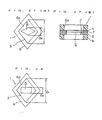
- FIGS. 21 (A) and 21(B) illustrate another modified form of the sensing unit 1 of FIG. 1, in which modified form the through hole 5 is in the form of a rhomb which has a longer diagonal D1 and shorter diagonal D2.
- the direction of the shorter diagonal D1 and the direction of the maximum breaking strength form the angel 0.
- Directivity output was measured on each sample by applying 200Hz, 1 G sinusoidal oscillation acceleration.
- the Directivity output is defined as the percentage of the output voltage V, which is provided when acceleration oscillation is applied in parallel with the plane of the piezo-electric element, over the output voltage which is generated when it is applied in the thicknesswise direction (main sensitive axis direction) thereof.
- Samples # 55 to # 60 prepared, and output voltage was obtained by applying sinusoidal oscillation at acceleration of 1 G in the frequency range from 2 Hz to 500 Hz.
- FIG. 22 shows output characteristics. Referring above results in Table 6 and FIG. 22, sample # 55 and sample # 56 provided larger output in the main sensitive axis direction than in a direction perpendicular to the main sensitive axis direction. The samples # 55 and # 56 had excellent directivity and stable output.
- FIGS. 23 (A) (B) illustrate a sensing unit 1 according to one embodiment of the present invention, which includes a disk-shaped laminate R having a disk-shaped diaphragm or oscillation plate 2, polymeric membrane piezo-electric element P made of a high polymer bonded on the surface of the diaphragm 2, and an electrode 4 attached on a surface of the piezo-electric element P.
- the diaphragm 2, the piezo-electric element P, and the electrode 4 are laminated in one body to form a laminate R.
- the laminate R has a pentagon through hole 5 concentrically formed through it and it is sandwiched at its peripheral portions of its opposite sides between a pair of ring-shaped fixing frames 6 and 6 in a stretched manner so that the circular through holes 6a thereof are arranged concentrically with the through hole 5 of the laminate R.
- the diaphragm 2 which vibrates when force is applied at its surface is made of 5mm thick nickel leaf to have larger rigidity then piezo-electric element P.
- E B elastic modulus of the diaphragm 2
- T B is thickness of the diaphragm 2
- Ep is elastic modulus of the piezo-electric element P
- Tp is thickness of the piezo-electric element P.
- the piezo-electric element P is made of high polymer, for instance oriented polyvinyliden fluoride film whose thickness is 9 mm and shaped substantially same figure of the diaphragm 2.
- the electrode 4 which is made of metal conductor material, is coated on a surface of the piezo-electric element P by thin-film forming, for instance vacuum deposition.
- Sample # 61 to # 68 of piezo-electric acceleration sensors having structures shown in FIG. 23 and similar structures were manufactured and prepared changing the number of angles in polygonal through hole and the ratio between cross-section area of the through hole 5 and area of the fixing frame 6 contacting the laminate R.
- Condition of the experiment is described as follows; material of the high polymer piezo-electric element is an oriented piezoelectric polyvinylidene fluoride film; thickness of the piezo-electric element is 9 mm; material of the diaphragm is nickel leaf; thickness of the diaphragm is 10 mm; outer diameter of the fixing frame is 12 mm; inner diameter of the fixing frame is 10 mm.
- an output voltage at magnitude of sinusoidal oscillation for measuring is 1 G; and frequency of the oscillation is below 10 Hz; is normalized.
- TAB. 7 shows the ratio between detected output and the normalized output under the above condition.
- * shows whether there is hole or no hole: b indicates blind; t indicates through.
- the output ratios of sample # 61 to # 63 are remarkably larger than the output ratios of sample # 64 to # 68 corresponding to the 13th embodiment. Hitherto, if the through hole 5 is an equilateral polygon that have above 5 angles, and the cross-sectional area of the through hole is in within the limit from 20 to 80 percent of the area of the fixing frame contacting on the laminate R, the output ratios are remarkably large. Especially, the sample # 61 that has no through hole generates output that is same as normalized output.
- FIGS. 24 (A), (B) and 25 illustrate a sensing unit 1 according to one embodiment of the present invention.
- the sensing unit 1 has the same structure as the unit in Example 12 in FIGS. 23 (A) (B) except as follows, i.e. , laminate R is elliptical-plate-shaped; a diaphragm or an oscillation plate 2, a piezo-electric element P, and an electrode 4 are elliptical-plate-shaped; a fixing flame 6 is an elliptical ring; and a through hole 5 is rectangle whose longer side is along to the minor axis of the elliptical hole 6a..
- the through hole 5 is shaped in the manner of following formula.
- FIG.25 illustrates another embodiment of the invention.
- the unit 1 wherein the FIG.25 has the same structure as the unit in the FIG. 24 except that the through hole is rhombus and its major diagonal is agreed with minor axis of the fixing frame 6.
- Samples # 69 to # 75 of piezo-electric acceleration sensors having the structures shown in FIGS. 24 and 25 and similar structures were prepared and the ratio of output voltage Vs over output voltage Vm was determined when the size and shape of its square through hole and the direction of the maximum braking strength were varied, where; the output voltage Vm was given by applying acceleration oscillation to each sample in the main sensitive axis , i.e., in the thicknesswise direction of the piezo-electric acceleration; and the output voltage Vs was given by applying acceleration oscillation to it in a direction perpendicular to the main sensitive axis direction ,i.e., in parallel with the plane of the piezo-electric device.
- the laminate which has 9mm thick piezo-electric polyvinylidene fluoride biaxially oriented film plated with 10mm thick nickel leaf layer, was held in elliptical-ring-shaped fixing frames having a 12mm major axis and 10mm minor axis elliptical through hole 6a, and output voltages were detected by applying 200 Hz and 1 G sinusoidal oscillation acceleration.
- samples # 69 to # 75 was tested, that is, output voltage from the samples was measured changing the sinusoidal oscillation acceleration in the area from 2 Hz to 500Hz.
- FIG. 26 illustrates the result of this test.
- samples # 69 and #75 has a characteristic, that is, ratio of the output voltage is low, these samples generates tolerably larger output in the main sensitive axis direction which has necessity for detection of acceleration than in a direction perpendicular to the main sensitive axis direction. Hitherto, those samples # 69 and # 75 generates little error.
- sample # 69 and # 75 generates largest output in the main sensitive axis direction compared with other samples and the output characteristic is substantially constant and stable.
- FIGS. 27 (A) (B) and 28 illustrate a sensing unit 1 according to one embodiment of the present invention.
- the sensing unit 1 has the same structure as the unit in Example 12 in FIGS. 23 (A) (B) except as follows, i.e. , laminate R is rhombric-plate-shaped; a diaphragm or an oscillation plate 2, a piezo-electric element P, and an electrode 4 are rhombric-plate-shaped; a through hole 5 is rhombric or rectangular; and a fixing flame is a rhombric ring.
- the through hole 5 is shaped in the manner that its longer diagonal is agreed to the shorter diagonal of the fixing frame 6. In this sensing unit 1, 0.2 ⁇ D 2 / D 1 ⁇ 0.8 where D 1 is the length of the longer diagonal of the fixing frame 6 and D 2 is the length of the shorter diagonal of the through hole 5.
- Samples # 76 to # 84 of piezo-electric acceleration sensors having structures shown in FIGS. 27 and 28 and similar structures were prepared as the same conditions and manners as samples of Example 13.
- difference of angle between direction agreeing to the maximum braking strength and direction of the shorter side is detertmined as 0.
- difference of angle between direction agreeing to the maximum braking strength and direction of the shorter diagonal is determined as 8.
- difference of angle between direction agreeing to the maximum braking strength and direction of the longer diagonal of the frame is determined as ⁇ .
- samples # 76 to # 84 is tested, that is, output voltage from the samples was measured changing the sinusoidal oscillation acceleration in the area from 2 Hz to 500Hz.
- FIG. 26 illustrates the result of this test.
- samples # 76 and # 77 has a characteristic, that is, ratio of the output voltage is low, these samples generates tolerably larger output in the main sensitive axis direction which has necessity for detection of acceleration than in a direction perpendicular to the main sensitive axis direction. Hitherto, those samples # 76 and # 77 generates little error.
- sample # 76 and # 77 generates largest output in the main sensitive axis direction compared with other samples and the output characteristic is substantially constant and stable.
- FIGS. 30(A) (B) and 31 illustrate a sensing unit A modified form of the sensor unit 1 of FIG. 21 is illustrated in FIGS. 30(A) and (B), in which all the members thereof, that is, diaphragm 2, piezo-electric element 3, electrode 4 and fixing frames 6, 6 are rectangular.
- the longer side D1 and the shorter side D2 meets the equation about 0.2 ⁇ D2/D1 ⁇ about0.8.
- the breaking strength of the piezo-electric element P depends on the direction, the element P is fixed between the frames 6 and 6 so that the maximum breaking strength direction thereof is placed along the direction of the longer side D1 within an angle 10° formed between them.
- FIG. 31 illustrates a modified form of the sensor unit in FIG. 20, which modified form is distinct in that all the members thereof are rectangular.
- Samples #85-93 were prepared and tested as to the directivity output (Vo/V)x100% in the same condition as in Example 10.
- Each sample had a 9 ⁇ m PVDF biaxially oriented film piezo-electric element, a 5 microns nickel layer diaphragm electroplated over the piezo-electric element, and a pair of fixing frames sandwiching the laminate and having a 12mm x 10mm rectangular through hole 6a.
- Other specifications of the samples are as follows: sample # 85 had the structure of FIG.
- sample #89 was the same as sample 86 except for a 10 mm longer side
- sample #90 was the same as sample #85 except for a 10 mm longer diagonal
- sample #91 was the same as sample #86 except for a 2 mm shorter side
- sample #93 has ring-shaped fixing frames with inner diameter 10 mm and the laminate had no hole 5. The results of the test are given in Table 10.
- FIGS. 33A and 33B show essential parts of piezo-electric acceleration sensors, and parts of a detection portion 1 corresponding to Embodiment 20.
- the detection portion 1 of the piezo-electric acceleration sensor in Embodiment 20 comprises, in the form of an integrated lamintate, an oscillation plate 2 formed into an elliptical plate, a film-like high polymeric piezo-electric element P adhered by adhesives to the surface of the oscillation plate 2 and an electrode 4 integrally mounted on the surface of the piezo-electric element P.
- the laminate is formed in its center with a round through-hole (a circular hole) 5, the laminate being supported within an elliptical hole (an oscillation hole) 6a in a stretched fashion in such a manner that a peripheral edge portion is held by an elliptical fixing portion (a fixing frame) 6.
- the oscillation plate 2 whose portion not in contact with the fixing portion 6 oscillates, is formed, for example, of a nickel foil having a thickness of 5 ⁇ m, and has a "deformation rigidity" enough to withstand the piezo-electric device 3.
- the oscillation plate 2 is set so as to have a relationship as follows: between the elastic modulus E B and thickness T s of the oscillation plate 2 and the elastic modulus Ep and thickness Tp of the piezo-electric device 3.
- the piezo-electric element P is formed from a high polymeric piezo-electric element, for example, a 9 ⁇ m thick polyvinylidene fluoride oriented film, and formed into a shape substantially similar to that of the oscillation plate 2.
- the electrode 4 is constructed in such a manner that metallic conductors are respectively integrally coated on both surfaces of the piezo-electric element P (one surface of which is omitted since in the example shown in FIG. 33, the oscillation plate 2 is formed of a conductive material such as a nickel foil) by a film forming method such as vapor deposition.
- Samples 94 to 104 of piezo-electric acceleration sensors having structures shown in FIG. 33 and similar structures, were prepared, and the ratio of output voltage Vs over output voltage Vm was determined when the shape of the fixing frame, the direction of the maximum breaking strength of the piezo-electric device, and the shape of the circular hole were varied, where the output voltage Vm was given by applying acceleration oscillation to each sample in the main sensitive axis, i.e., the thicknesswise direction of the piezo-electric acceleration; and the output voltage Vs was given by applying acceleration oscillation to it in a direction perpendicular to the main sensitive axis direction, i.e., in parallel with the plane of the piezo-electric device. The output voltages were detected by applying 200 Hz and 1 G sinusoidal oscillation acceleration.
- a laminate which comprises a 9 pm thick piezo-electric poly vinylidene fluoride oriented film as a high polymeric piezo-electric element and a 10 ⁇ m thick nickel foil as an oscillation plate, was held in a fixing frame having a 12 mm outside diameter and 10 mm inside diameter to form a detection portion.
- the detection portion was bored in its central portion with a circular hole by a laser trimmer, the circular hole being set so that the ratio of area of the film portion was 800/0 of an area of the frame.
- a fixing frame in the form of an elliptical hole having the same inner area as that of the sample 94 a circular hole was bored in the central portion of a film portion to prepare a detection portion whose ratio of area is 80%.
- the ratio of the minor axis to the long diameter of the elliptical hole was set to 2 : 3, and the angle formed between the direction of the minor axis and the direction of the maximum breaking strength of the piezo-electric element was set to 20 degrees.
- the sample piezo-electric element and oscillation plate as those of Sample 94 were used.
- the ratio of the minor axis axis and the major axis of the elliptical hole was set to 2 : 3, and the angle formed between the direction of the short diameter and the direction of the maximum breaking strength of the piezo-electric element set to 40 degrees.
- the angle formed between the direction of the minor axis of the elliptical hole and the direction of the maximum breaking strength of the piezo-electric element was set to 5 degrees.
- a circular hole wherein an area of a film portin is 900/0 of an area of the elliptical hole was made. Other conditions were set similarly to the Sample 95.
- the ratio of area of the film portion was set to 95%.
- the ratio of area of the film portion was set to 15%.
- a circular hole wherein the ratio of area of the film portion is 500/0 was used, and other conditions were set similarly to those of Sample 100.
- a circular hole wherein the ratio of area of the film portion is 800/0 was used, and other conditions were set similarly to those of Sample 100.
- the angle formed between the direction of the minor axis of the elliptical hole and the direction of the maximum breaking strength of the piezo-electric element was set to 7 degrees, and other conditions were set similarly to those of Sample 100.
- the ratio of the minor axis to the major axis of the elliptical hole was set to 3 : 5, and other conditions were set similarly to those of Sample 100.
- the ratio of output voltage represents the value per 1 G with respect to 1 in Sample 94, and the ratio of sensitivity between longitudinal and lateral portion is %.
- FIGS. 34A and 34B show essential parts of piezo-electric acceleration sensors and parts of a detection portion 1 corresponding to Embodiment 21.
- the detection portion 1 of the piezo-electric acceleratin sensor in Embodiment 21 comprises, in the form of an integrated laminate, an oscillation plate 2 formed into an elliptical plate, a film-like high polymeric piezo-electric element P adhered by adhesives to the surface of the oscillation plate 2 and an electrode 4 integrally mounted on the surface of the piezo-electric element P.
- the laminate R is formed in its center portion with a through-hole (an elliptical hole) 5, the laminate R being supported within an elliptical hole 6a in a stretched fashion in such a manner that a peripheral edge portion thereof is held by a elliptical fixing portion (a fixing frame) 6.
- the oscillation plate 2 whose portion not in contact with the fixing portion 6 oscillates, is formed, for example, of a nickel foil having a thickness of 10 ⁇ m, and has a "deformation rigidity" enough to withstand the piezo-electric device 3.
- the oscillation plate 2 is set so as to have a relationship as follows: between the elastic modulus E s and thickness T e of the oscillation plate 2 and the elastic modulus Ep and thickness Tp of the piezo-electric device 3.
- the piezo-electric element P is formed from a high polymeric piezo-electric element, for example, a 9 ⁇ m thick polyvinylidene fluoride oriented film, and formed into a shape substantially similar to that of the oscillation plate 3.
- the electrode 4 is constructed in such a manner that metallic conductors are respectively integrally coated on both surfaces of the piezo-electric element P (one surface of which is omitted since in the example shown in FIG. 34 the oscillation plate 2 is formed of a conductive material such as a nickel foil) by a film forming method such as vapor deposition.
- Samples 105 to 116 of piezo-electric acceleration sensors having structures shown in FIG. 34 and similar structures, were prepared, and the ratio of output voltage Vs over output voltage Vm was determined when the shape of the fixing frame, the direction of the maximum breaking strength of the piezo-electric device, and shape of the circular hole were varied, where the output voltage Vm was given by applying acceleration oscillation to each sample in the main sensitive axis, i.e., the thicknesswise direction of the piezo-electric acceleration; and the output voltage Vs was given by applying acceleration oscillation to it in a direction perpendicular to the main sensitive axis direction, i.e., in parallel with the plane of the piezo-electric device. The output voltages were detected by applying 200 Hz and 1 G sinusoidal oscillation acceleration.
- Sample 105 was prepared in a manner similar to that of Sample 94 previously described.
- a piezo-electric film formed in its center portion with an elliptical hole and an elliptical fixing frame were used to constitute a detection portion so that an area of a film (piezo-electric device) portion is the same as that of Sample 105.
- the ratio of the minor axis to the major axis of the elliptical hole was set to 2 : 3, an area of the elliptical hole was set to 200/0 of the elliptical hole, and the angle formed between the direction of the major axis of the elliptical hole and the direction of the maximum breaking strength of the piezo-electric element was set to 20 degrees.
- the angle formed between the direction of the major axis of the piezo-electric device and the direction of the maximum breaking strength of the piezo-electric element was to set to 5 degrees, and the area of the elliptical bore was set so as to be 900/0 of that of the elliptical hole.
- the angle formed betweeen the direction of the long diameter of the piezo-electric element and the direction of the maximum breaking strength of the piezo-electric element was set to 5 degrees, and the area of the ellipical bore was set to be 10% of that of the elliptical hole.
- the area of the elliptical bore was set to be 50 0 /o of that of the elliptical hole.
- the angle formed between the direction of the long diameter of the piezo-electric element and the direction of the maximum breaking strength of the piezo-electric element was set to 5 degrees, the area of the elliptical bore was set to 20% of that of the elliptical hole, and the dimension in FIG. 34 was set to L ⁇ 1.
- the same film as Sample105 was used to prepare a detection portion.
- the ratio of the long diameter to the short diameter of the elliptical bore and elliptical hole was set to 3 : 2
- the angle formed between the direction of the long diameter of the piezo-electric device and the direction of the maximum breaking strength of the piezo-electric device was set to 5 degrees
- the area of the film portion was to set to 80 0 / 0 of that of the elliptical hole
- the dimension in FIG. 34 was set to L ⁇ 1.
- the angle formed between the direction of the major axis of the piezo-electric element and the direction of the maximum breaking strength of the piezo-electric element was set to 7 degrees, and for others, the same conditions as those of Sample 112 were used.
- the ratio of the major axis to the minor axis of the elliptical bore and elliptical hole was set to 5 : 3, and for others, the same conditions as those of Sample 112 were used.
- FIGS. 35 A and 35B show essential parts of piezo-electric acceleration sensors , and parts of a detection portion 1 corresponding to Embodiment 22.
- the detection portion 1 of the piezo-electric acceleration sensor in Embodiment 22 comprises, in the form of an integrated laminate, an oscillation plate 2 formed into a disc, a film-like high polymeric piezo-electric element P adhered by adesives to the surface of the oscillation plate 2 and an electrode 4 integrally mounted on the surface of the piezo-electric element P.
- the laminate R is formed in its center portion with a through-hole (an elliptical hole) 5, the laminate R being supported within a circular hole (an oscillation hole) 6a of the fixing portion in a stretched fashion in such a manner that a peripheral edge portion thereof is held by an annular fixing portion (a fixing frame) 6.
- the oscillation plate 2 whose portion not in contact with the fixing portion 6 oscillates, is formed, for example, of a nickel foil having a thickness of 10 ⁇ m, and has a "deformation rigidity" enough to withstand the piezo-electric device 3.
- the oscillation plate 2 is set so as to have a relationship as follows: between the elastic modulus Ei3 and thickness T B of the oscillation plate 2 and the elastic modulus Ep and thickness Tp of the piezo-electric device 3.
- the piezo-electric element P is formed from a high polymeric piezo-electric element for example, a 9 ⁇ m thick polyvinylidene fluoride oriented film, and formed into a shape substantially similar to that of the oscillation plate 2.
- the electrode 4 is constructed in such a manner that metallic conductors are respectively integrally coated on both surfaces of the piezo-electric element P . (one surface of which is omitted since in the example shown in FIG. 35, the oscillation plate 2 is formed of a conductive material such as a nickel foil) by a film forming method such as vapor deposition.
- Sample 117 was prepared in a manner similar to that of Sample 94 previously described.
- a detection portion of a piezo-electric element having an annular fixing portion having the same diameter as that of Sample 117 and an elliptical bore was prepared.
- An area of a film portion is the same as that of Sample 117.
- the ratio of the minor axis to the major axis of the elliptical bore was 2 : 3, and the angle formed between the direction of the minor axis and the direction of the maximum breaking strength of the piezo-electric device was set to 20 degrees.
- the angle formed between the direction of the minor axis of the elliptical bore formed in the piezo-electric device and the direction of the maximum breaking strength of the piezo-electric device was set to 40 degrees. Others are the same as Sample 118.
- the angle formed between the short diameter of the elliptical hole and the direction of the maximum breaking strength of the piezo-electric element was set to 5 degrees, and the area of the film portion was set to be 900/0 of that of the circular hole. Others are the same as Sample 118.
- an area of a film portion was set to be 95 0 /o of that of a circular hole.
- the same film as that of Sample 117 was used to prepare a detection portion.
- the fixing portion was formed with a circular hole.
- the piezo-electric device was formed with an elliptical bore.
- the ratio of the major axis to the minor axis of the elliptical bore was set to 3 : 2.
- the angle formed between the direction of the maximum breaking strength of the piezo-electric device and the direction of the minor axis of the elliptical bore was set to 5 degrees, and the area of the film portion was 20 % of that of the circular hole.
- the angle formed between the direction of the maximum breaking strength of the piezo-electric device and the minor axis of the elliptical bore was set to 7 degrees. For others, the same conditions as those of Sample 123 were used.
- the ratio of the long diameter to the minor axis of the elliptical bore and the circular hole was set to 5 : 3.
- the ratio of output voltage represents the value per 1 G with respect to 1 in Sample 117.
- FIGS. 36 A and 36 B show essential parts of piezo-electric acceleration sensores, and parts of a detection portion 1 corresponding to Embodiment 23.
- the detection portion 1 of the piezo-electric acceleration sensor in Embodiment 23 comprises, in the form of an integrated laminate, an oscillation plate 2 formed into a disk, a film-like high polymeric piezo-electric element P adhered by adhesives to the surface of the oscillation plate 2 and an electrode 4 integrally mounted on the surface of the piezo-electric device.
- the laminate R is formed in its center portion with a through-hole (a triangular hole) 5 with the center of gravity coincided, the laminate R being supported within a circular hole (an oscillation hole) 6a in a stretched fashion in such as manner that a peripheral edge portion thereof is held by an annular fixing portion (a fixing frame) 6.
- the piezo-electric element P is formed from a high polymeric piezo-electric element for example, a 9 pm thick polyvinylidene fluoride oriented film, and formed into a shape substantially similar to that of the oscillation plate 3.
- the electrode 4 is constructed in such a manner that metallic conductors are respectively integrally coated on both surfaces of the piezo-electric element P (one surface of which is omitted since in the example shown in FIG. 34, the oscillation plate 2 is formed of a conductive material such as a nickel foil) by a film forming method such as vapor deposition.
- Samples 128 to 134 of piezo-electric acceleration sensors having structures shown in FIG. 36 and similar structures, were prepared, and the direction of the maximum breaking strength of the piezo-electric device and the shape of the triangular hole were varied for comparision.
- the high polymeric piezo-electric film a 9 ⁇ m thick piezo-electric poly vinylidene fluoride oriented film was used, and as the oscillation plate, a 5 1 1m thick nickel plated layer was formed on the piezo-electric film by electro-plating.
- the laminate was held by an annular fixing portion having a 12 mm outside diameter and an inside diameter 10 mm to form a detection portion.
- a regular triangle hole whose one side has a length of 3.5 mm was made in the center of the laminate which is the oscillation portion. It was set so that an angle of 90 degrees was formed between the direction exhibiting the maximum breaking strength of the piezo-electric device and one side of the regular triangle hole.
- a regular triangle hole whose one-side length is 8 mm was made in the laminate. It was set so that an angle of 90 degrees was formed between the direction exhibiting the maximum breaking strength and one side of the regular triangle hole.
- a regular triangle hole whose one-side length is 1.5mm was made in the laminate. It was set so that an angle of 90 degrees was formed between the direction exhibiting the maximum breaking strength and one side of the regular triangle hole.
- a regular triangle hole whose one-side length is 3.5mm was made in the laminate. It was set so that an angle of 0 degree was formed between the direction exhibiting the maximum breaking strength and one side of the triangle hole.
- a regular square hole whose one-side length is 2.3 mm was made in the laminate. It was set so that an angle of 90 degrees was formed between the direction of the maximum breaking strength and one side of the regular square hole.
- a laminate withou being formed with a hole was prepared.
- 200 Hz and 1 G sinusoidal oscillation acceleratin was applied to the main sensitive axis direction (thicknesswise direction of the piezo-electric device) and the direction of 90 degrees thereof to obtain the ratio of the output voltages:
- FIGS. 36 A and 36 B show essential parts of piezo-electric acceleration sensores, and parts of a detection portion 1 corresponding to Embodiment 23
- the detection portion 1 of the piezo-electric acceleration sensor in Embodiment 23 comprises, in the form of an integrated laminate, an oscillation plate 2 formed into a disc, a film-like high polymeric piezo-electric element P adhered by adesives to the surface of the oscillation plate 2 and an electrode 4 integrally mounted on the surface of the piezo-electric element.
- the laminate R is formed in its center portion with a through-hole (an triangular hole) 5 with the center of gravity coincided, the laminate R being supported within a circular hole (an oscillation hole) 6a in a stretched fashion in such a manner that a peripheral edge portion thereof is held by by an annular fixing portion (a fixing frame) 6.
- the piezo-electric element P is formed from a high polymeric piezo-electric element, for example, a 9 1 1m thick polyvinylidene fluoride oriented film, and formed into a shape substantially similar to that of the oscillation plate 2.
- the electrode 4 is constructed in such a manner that metallic conductors are respectively integrally coated on both surfaces of the piezo-electric element P (one surface of which is omitted since inthe example shown in FIG. 36, the oscillation plate 2 is formed of a conductive material such as a nickel foil) by a film forming method such as vapor deposition.
- FIGS. 38 A and 38B show essential parts of piezo-electric acceleration sensores, and parts of a detection portion 1 corresponding to Embodiment 24.
- the detection portion 1 of the piezo-electric acceleration sensor in Embodiment 23 comprises, in the form of an integrated laminate, an oscillation plate 2 formed into a square film-like high polymeric piezo-electric element P adhered by adesives to the surface of the oscillation plate 2 and an electrode 4 integrally mounted on the surface of the piezo-electric device.
- the laminate R is formed in its center portion with a through-hole (a triangular hole) 5 with the center of gravity coincided, the laminate being supported within an oscillation hole (a rhombric shape ) 6a in a stretched fashion in such a manner that a peripheral edge portion thereof is held by a rhombric fixing portion (a fixing frame) 6.
- the piezo-electric element P is formed from a high polymeric piezoelectric element, for example, a 9 1 1m thick polyvinylidene fluoride oriented film, and formed into a shape substantially similar to that of the oscillation plate 2.
- the electrode 4 is constructed in such a manner that metallic conductors are respectively integrally coated on both surfaces of the piezo-electric element P (one surface of which is omitted since inthe example shown in FIG. 38, the oscillation plate 2 is formed of a conductive material such as a nickel foil) by a film forming method such as vapor deposition.
- Samples 135 to 143 to piezo-electric acceleration sensores having structures shown in FIG. 38 and similr structures, were prepared, and the direction of the maximum breaking strength of the piezo-electric element and the shape of the triangular hole were varied for comparison.
- the high polymeric piezo-electric film a 9 ⁇ m thick piezo-electric poly vinylidene fluoride oriented film was used, and as the oscillation plate, a 5 ⁇ m thick nickel plated layer was formed on the piezo-electric film by electro-plating.
- the laminate was supported within a rhombric hole of a fixing portion comprising a rhombric frame in a stretched fashion, and the diagonal lines of the diamond hole have the dimensions of a 12 mm longer one and a 9 mm shorter one.
- a regular triangle hole whose one side has a length of 3.5 mm was made in the center of the laminate which is the oscillation portion. It was so set that an angle of 90 degrees was formed between the direction exhibiting the maximum breaking strength of the piezo-electric device and one side of the regular triangle hole and that an angle of 90 degrees was formed between the direction exhibiting the maximum breaking strength and the shorter diagonal.
- a triangular hole was formed into an equilateral triangle whose bottom-side length is 4 mm and median line length is 7.5 mm. It was set so that an angle of 90 degrees was formed between the direction exhibiting the maximum breaking strength and one side of the equilateral triangle hole and an angle of 90 degrees was formed between the direction exhibiting the maximum breaking strength and the shorter diagonal.
- a regular triangle hole whose one-side length is 1.5 mm was made. It was set so that an angle of 90 degrees was formed between the direction exhibiting the maximum breaking strength and one side of the regular triangle hole and an angle of 90 degrees was formed between the direction of the maximum breaking strength and the shorter diagonal.
- a regular triangle hole whose one-side length is 3.5 mm was made. It was set so that an angle of 0 degrees was formed between the direction exhibiting the maximum breaking strength and one side of the regular triangle hole and an angle of 90 degrees was formed between the direction of the maximum breaking strength and the shorter diagonal.
- a regular square hole whose one-side length is 2.3 mm was made in place of a triangular hole. It was set so that an angle of 90 degrees was formed between the direction exhibiting the maximum breaking strength and one side of the regular square hole, and an angle of 90 degrees was formed between the direction exhibiting the maximum breaking strength and the shorter diagonal.
- a regular triangle hole whose one-side length is 3.5 mm was made. It was set so that an angle of 90 degrees was formed between the direction exhibiting the maximum breaking strength and one side of the regular triangle hole and an angle of 0 degree was formed between the direction exhibiting the maximum breaking strength and the shorter diagonal.
- a fixing portion was made in the form of a circular hole, and a laminate was not formed with a hole.
- a rhombric hole was made, and a laminate was not formed with a hole. It was set so that an angle of 90 degrees was formed between the direction exhibiting the maximum breaking strength and the shorter diagonal.
- the middle line is used for the equilateral triangle.
- FIGS. 40 A and 40B show essential parts of piezo-electric acceleration sensores, and parts of a detection portion 1 corresponding to Embodiment 25.
- the detection portion 1 of the piezo-electric acceleration sensor in Embodiment 25 comprises, in the form of an integrated laminate, an oscillation plate 2 formed into an ellipse film-like high polymeric piezo-electric element P adhered by adesives to the surface of the oscillation plate 2 and an electrode 4 integrally mounted on the surface of the piezo-electric element.
- the laminate R is formed in its center portion with a through-hole (as triangular hole) 5 with the center of gravity coincided, the laminate R being supported within an elliptical hole 6a in a stretched fashion in such a manner that a peripheral edge portion thereof is held by an elliptical fixing portion (a fixing frame) 6 whereby a median line of the triangular hole 5 is coincided with the direction of the major axis of the oscillation hole (elliptical hole ) 6a.
- the piezo-electric element P is formed from a high polymeric piezoelectric element, for example, a 9 f.Lm thick polyvinylidene fluoride oriented film, and formed into a shape substantially similar to that of the oscillation plate 2.
- the electrode 4 is constructed in such a manner that metallic conductors are respectively integrally coated on both surfaces of the piezo-electric element P(one surface of which is omitted since inthe example shown in FIG. 40, the oscillation plate 2 is formed of a conductive material such as a nickel foil) by a film forming method such as vapor deposition.
- Samples 144 to 152 of piezo-electric acceleration sensores having structures shown in FIG. 40 and similr structures, were prepared, and the direction of the maximum breaking strength of the piezo-electric device and the shape of the triangular hole were varied for comparison.
- the high polymeric piezo-electric film a 9 ⁇ m thick piezo-electric poly vinylidene fluoride oriented film was used, and as the oscillation plate, a 5 ⁇ .t.m thick nickel plated layer was formed on the piezo-electric film by electro-plating.
- the laminate was supported in a stretched fashion within the elliptical hole of the fixing position comprising an elliptical frame, and the elliptical hole has the dimensions of a 12 mm major axis and a 9 mm minor axis.
- a regular triangle hole whose one side has a length of 3.5 mm was made in the center of the laminate which is the oscillation portion. It was set so that an angle of 90 degrees was formed between the direction exhibiting the maximum breaking strength of the piezo-electric device and one side of the regular triangle hole and an angle of 90 degrees was formed between the direction exhibiting the maximum breaking strength and the short diameter.
- a regular triangle hole whose one-side length is 9 mm was made in the center of the laminate. It was set so that an angle of 90 degrees was formed between the direction exhibiting the maximum breaking strength and one side of the regular square hole, and an angle of 90 degrees was formed between the direction exhibiting the maximum breaking strength and the minor axis.
- a regular triangle hole whose one-side length is 1.5 mm was made. It was set so that an angle of 90 degrees was formed between the direction exhibiting the maximum breaking strength and one side of the regular triangle hole, and an angle of 90 degrees was formed between the direction exhibiting the maximum breaking strength and the minor axis.
- a regular triangle hole whose one-side length is 3.5 mm was made. It was set so that an angle of 0 degree was formed between the direction exhibiting the maximum breaking strength and one side of the triangle hole, and an angle of 90 degrees was formed between the direction exhibiting the maximum breaking strength and the minor axis.
- a regular square hole whose one-side length is 2.3 mm was made in place of a triangular hole. It was set so that an angle of 90 degrees was formed between the direction exhibiting the maximum breaking strength and one side of the regular square hole, and an anlge of 90 degrees was formed between the direction exhibiting the maximum breaking strength and the minor axis.
- a regular triangle hole whose one side length is 3.5 mm was made. It was set so that an angle of 90 degrees was formed between the direction exhibiting the maximum breaking strength and one side of the regular triangle hole and an angle of 0 degree was formed between the direction exhibiting the maximum breaking strength and the minor axis.
- a circular hole having a 10 mm internal diameter was made to form a fixing portion, and a regular triangle hole whose one-side length is 3.5 mm was made. It was set so that an angle of 90 degrees was formed between the direction exhibiting the maximum breaking strength and one end of the regular triangle hole.
- An elliptical hole was made, and a laminate without being formed with a hole was prepared. It was set so that an angle of 90 degrees was formed between the direction of the maximum breaking strength and the minor axis.
- a triangular hole preferably comprises an equilateral triangle hole including a regular triangle hole.
- a middle line between the equilateral sides may be coincided with a long diameter of an elliptical hole to thereby make an improved effect of characteristics remarkable.
- FIGS. 42A and 42B show essential parts of piezo-electric acceleration sensores, and parts of a detection portion 1 corresponding to Embodiment 27.
- the detection portion 1 of the piezo-electric acceleration sensor in Embodiment 26 comprises, in the form of an integrated laminate, an oscillation plate 2 formed into a square film-like high polymeric piezo-electric element P adhered by adesives to the surface of the oscillation plate 2 and an electrode 4 integrally mounted on the surface of the piezo-electric device.
- the laminate R is formed in its center portion with a through-hole (an elliptical hole) 5, the laminate R being formed in the center portion thereof with a through-hole (a circular hole) 5, the laminate R being supported within an oscillation hole (an equilateral square hole) 6a in a stretched fashion in such a manner that a peripheral edge portion thereof is held by a regular square fixing portion (a fixing frame) 6.
- the oscillation plate 2 whose portion not in contact with the fixing portion 6 oscillates, is formed, for example, of a nickel foil having a thickness of 10 ⁇ m, and has a "deformation rigidity" enough to withstand the piezo-electric device 3.
- the oscillation plate 2 is set so as to have a relationship as follows: between the elastic modulus E B and thickness T B of the oscillation plate 2 and the elastic modulus Ep and thickness Tp of the piezo-electric device 3.
- the piezo-electric element P is formed from a high polymeric piezo-electric device, for example, a 9 ⁇ m thick polyvinylidene fluoride oriented film, and formed into a shape substantially similr to that of the oscillation plate 2.
- the electrode 4 is constructed in such a manner that metallic conductors are respectively integrally coated on both surfaces of the piezo-electric element P (one surface of which is omitted since in the example shown in FIG. 42, the oscillation plate 2 is formed of a conductive material such as a nickel foil) by a film forming method such as vapor deposition.
- FIG. 43 shows the 27th embodiment in which the peripheral edge portion of the laminate is held by the diamond fixing portion (a fixing frame) 6 to thereby support it within the equilateral square hole 6a in a stretched fashion.
- Samples 153 to 169 of piezo-electric acceleration sensors having structures shown in FIGS. 42 and 43 similar structures, were prepared, and the shape of the equilateral square hole, the area ratio of the circular holes, the direction of the maximum breaking strength of the piezo-electric device are varied for comparision.
- As the high polymeric piezo-electric film a 9 ⁇ m thick piezo-electric poly vinylidene fluoride oriented film was used, and said film was cemented to a 10 ⁇ m thick nickel foil,which was then held by the fixing frame to form a detection portion.
- the output ratio represents the value per 1G when the output voltage in Sample 153 is 1.
- FIGS. 44 A and 44B show essential parts of piezo-electric acceleration sensores, and parts of a detection portion 1 corresponding to Embodiment 28, that is, the inventions in Claims 45 to 47.
- the detection portion 1 of the piezo-electric acceleration sensor in Embodiment 28 comprises, in the form of an integrated laminate, an oscillation plate 2 formed into square a film-like high polymeric piezo-electric element P adhered by adhesives to the surface of the oscillation plate 2 and an electrode 4 integrally mounted on the surface of the piezo-electric device.
- the laminate R is formed in its center portion with a through-hole (an elliptical hole) 5 with the long diameter adjusted to the direction parallel to one side of the regular square, the laminate R being supported within an oscillation hole (a square hole of a regular square) in a stretched fashion in such a manner that a peripheral edge portion thereof is held by a fixing portion (a fixing frame) 6 of the regular square.
- the oscillation plate 2 whose portion not in contact with the fixing portion 6 oscillates, is formed, for example, of a nickel foil having a thickness of 10 J lm, and has a "deformation rigidity" enough to withstand the piezo-electric device 3.
- the oscillation plate 2 is set so as to have a relationship as follows: between the elastic modulus E B and thickness T B of the oscillation plate 2 and the elastic modulus Ep and thickness Tp of the piezo-electric device 3.
- the piezo-electric element P is formed from a high polymeric piezo-electric element, for example, a 9 ⁇ m thick polyvinylidene fluoride oriented film, and formed into a shape substantially similar to that of the oscillation plate 2 with the arrangement wherein the direction of the maximum breaking strength where the breaking strengths are different between longitudinal and lateral directions is brought into coincidence with the direction perpendicular to the direction of the long side of the square hole 6a.
- a high polymeric piezo-electric element for example, a 9 ⁇ m thick polyvinylidene fluoride oriented film
- the electrode 4 is constructed in such a manner that metallic conductors are respectively integrally coated on both surfaces of the piezo-electric element P (one surface of which is omitted since in the example shown in FIG. 44 , the oscillation plate 2 is formed of a conductive material such as a nickel foil) by a film forming method such as vapor deposition.
- Samples 170 to 180 of piezo-electric acceleration sensors having structures shown in FIG. 44 and similar structures, were prepared, and the shape of the square hole of the fixing portion, the area ratio of the elliptical hole, the direction of the maximum breaking strength of the piezo-electric device and the length of the film portion were varied to obtain an output voltage when the acceleration oscillation was applied in the direction of the main sensitive axis (the thicknesswise direction of the piezo-electric device) for comparison.
- the output voltages were detected by applying 200 Hz and 1 G sinusoidal oscillation acceleration.
- the high polymeric piezo-electric film a 9 ⁇ m thick piezo-electric poly vinylidene fluoride oriented film was used, and said film was cemented to a 10 ⁇ m thick nickel foil, which was then held by a round annular fixing frame having a 12 mm outside diameter and a 10 mm inside diameter to form a detection portion.
- the fixing frame is formed in the central portion thereof with a circular hole in which the film portion is 80 0 / 0 of the area of the hole of the fixing portion, by a laser trimmer.
- the area of a film portion (except a hole of a laminate) is the same as Sample 170.
- a rectangular fixing portion (the ratio of short to long sides of the rectangular hole is 1 : 1.5).
- L be the length in the direction exhibiting the maximum breaking strength of the film portion surrounding the elliptical hole in the center portion and let 1 be the length of the film portion perpendicularly intersecting each other, then the relation of L a 1 is established.
- the area of the elliptical hole in the center is 20 0 / 0 of the area of the regular square hole.
- the angle formed between the direction of the long side of the square hole, the direction of the short diameter of the elliptical hole and the direction exhibiting the maximum breaking strength by the film is 20 degrees.
- the aforesaid angle is 40 degrees, and others are the same as Sample 171.
- the angle is 5 degrees, and the area of the elliptical hole is 90 % of the square hole. Others are the same as Sample 171.
- the angle is 5 degrees, and the area of the elliptical hole is 10 %. Others are the same as Sample 171.
- the area of the elliptical hole is 50/ 0 , and others are the same as Sample 171.
- the angle is 5 degrees, and the area of the elliptical hole is 15 %, L ⁇ l. Others are the same as Sample 171.
- the angle is 5 degrees, and the area of the elliptical hole is 10%, L ⁇ l. Others are the same as Sample 171.
- the area of the film portion is 500/0 of the square hole, and others are the same as Sample 171.
- the area of the film portion is 800/0 of the square hole, and others are the same as Sample 171.
- the angle is 7 degrees, and others are the same as Sample 177.
- the output ratio represents the value per 1 G when the output voltage in Sample 170 is 1.
- FIGS. 45 A and 45 B show essential parts of piezo-electric acceleration sensores, and parts of a detection portion 1 corresponding to Embodiment 29.
- the detection portion 1 of the piezo-electric acceleration sensor in Embodiment 29 comprises, in the form of an integrated laminate, an oscillation plate 2 formed into a square film-like high polymeric piezo-electric element P adhered by adhesives to the surface of the oscillation plate 2 and an electrode 4 integrally mounted on the surface of the piezo-electric device.
- the laminate R is formed in its center portion (in case of a rectangular hole, a point of, intersection between the diagonal lines A and B) with a through-hole (a triangular hole ) 5 with the center of gravity G coincided, the laminate R being supported within a rectangular hole (an oscillation hole) 6a in a stretched fashion in such a manner that a peripheral edge portion thereof is held by a square fixing portion (a fixing frame) 6.
- a triangular hole 5 is an equilateral triangle
- a middle line C at right angle to the bottom side is parallel with the long-side direction of the rectangular hole 6a.
- the piezo-electric element P is formed from a high polymeric piezoelectric device, for example, a 9 ⁇ m thick polyvinylidene fluoride oriented film, and formed into a shape substantially similar to that of the oscillation plate 3.
- the electrode 4 is constructed in such a manner that metallic conductors having a 5 I Lm thickness are respectively integrally coated on both surfaces of the piezo-electric element P(one surface of which is omitted since inthe example shown in FIG. 45, the oscillation plate 2 is formed of a conductive material such as a nickel foil) by a film forming method such as vapor deposition.
- Samples 181 to 189 of piezo-electric acceleration sensors having structures shown in FIG. 45 and similar structures, were prepared, and the direction of the maximum breaking strength of the piezo-electric deivce and the shape of the triangular hole were varied for comparison.
- the high polymeric piezo-electric film a 9 I Lm thick piezo-electric poly vinylidene fluoride oriented film was used, and as the oscillation plate, a 5 ⁇ m thick nickel plated layer was formed on the piezo-electric film by electro-plating.
- the laminate is supported in a stretched fashion within a rectangular hole of a fixing portion comprising a rectangular frame.
- the rectangular hole has the dimension of a 10 mm long diameter and a 8 mm short diameter.
- a regular triangle hole having a 20 mm length of one side is made in the center of a laminate which is an oscillation portion. It was set so that an angle of 90 degrees was formed between the direction exhibiting the maximum breaking strength of the piezo-electric device and one end of a regular triangle hole, and an angle of 90 degrees was formed between the direction exhibiting the maximum breaking angle and the short side.
- a equilateral triangle hole whose bottom-side length is 3 mm and middle-line length is 2.6 mm was made in a laminate. It was set so that an angle of 90 degrees was formed between the direction exhibiting the maximum breaking strength and one side of the equilateral triangle hole and an angle of 90 degrees was formed between the direction exhibiting the maximum breaking strength and the short side.
- a triangular hole comprises an equilateral triangle whose bottom-side length is 3.5 mm and middle-line length is 6 mm). It was set so that an angle of 90 degrees was formed between the direction exhibiting the maximum breaking strength and one side of the equilateral triangle hole, and an angle of 90 degrees was formed between the direction exhibiting the maximum breaking strength and the short diameter.
- a regular triangle hole whose one-side length is 1 mm) was made. It was set so that an angle of 90 degrees was formed between the direction exhibiting the maximum breaking strength and one side of the regular triangle hole, and an angle of 90 degrees was formed between the direction exhibiting the maximum breaking strength and the short side.
- a regular triangle hole whose one-side length is 2 mm was made. It was set so that an angle of 0 degree was formed between the direction exhibiting the maximum breaking strength and one side of the regular triangle hole, and an angle of 90 degrees was formed between the direction exhibiting the maximum breaking strength and the short side.
- a regular square hole whose one-side length is 2 mm was made in place of a triangular hole. It was set so that an angle of 90 degrees was formed between the direction exhibiting the maximum breaking strength and one side of the regular triangle hole, and an angle of 90 degrees was formed between the direction exhibiting the maximum breaking strength and the short side.
- a regular triangle hole whose one-side length is 2 mm was made. It was set so that an angle of 90 degrees was formed between the direction of the maximum breaking strength and one side of the regular triangle hole, and an angle of 0 degree was formed between the direction exhibiting the maximum breaking strength and the short side.
- a fixing portion was formed into a circular hole having a 10 mm inside diameter, and a laminate without being formed with a hole was prepared.
- a square hole was prepared, and a laminate without being formed with a hole was prepared. It was set so that an angle of 90 degrees was formed between the direction exhibiting the maximum breaking strength and the short side.
- the IG sinusoidal oscillation acceleration was applied to each of the samples with the frequencies varied from 2 Hz to 500 Hz to measure the output voltages.
- the output characteristics are given in FIG. 46.
- the middle line is used for the equilateral triangle.
- FIGS. 47 A and 47B show essential parts of piezo-electric acceleration sensores, and parts of a detection portion 1 corresponding to Embodiment 30.
- the detection portion 1 of the piezo-electric acceleration sensor in Embodiment 30 comprises, in the form of an integrated laminate, an oscillation plate 2 formed into rectangular film-like high polymeric piezo-electric element P adhered by adhesives to the surface of the oscillation plate 2 and an electrode 4 integrally mounted on the surface of the piezo-electric element.
- the laminate R is formed in its center portion with a through-hole (a circular hole) 5, the laminate R being supported within a rectangular hole (an oscillation hole) 6a in a stretched fashion in such a manner that a peripheral edge portion thereof is held by a rectangular fixing portion (a fixing frame) 6.
- the oscillation plate 2 whose portion not in contact with the fixing portion 6 oscillates, is formed, for example, of a nickel foil having a thickness of 10 ⁇ .tm, and has a "deformation rigidity" enough to withstand the piezo-electric device 3.
- the oscillation plate 2 is set so as to have a relationship as follows: between the elastic modulus E B and thickness T B of the oscillation plate 2 and the elastic modulus Ep and thickness Tp of the piezo-electric device 3.
- the piezo-electric element P is formed from a high polymeric piezo-electric device, for example, a 9 ⁇ m thick polyvinylidene fluoride oriented film, and formed into a shape substantially similr to that of the oscillation plate 2.
- the electrode 4 is constructed in such a manner that metallic conductors are respectively integrally coated on both surfaces of the piezo-electric element P (one surface of which is omitted since in the example shown in FIG. 47, the oscillation plate 2 is formed of a conductive material such as a nickel foil) by a film forming method such as vapor deposition.
- a 9 ⁇ m thick piezo-electric poly vinylidene fluoride oriented film was used as a high polymeric piezo-electric device, and an element obtained by cementing it to a 10 ⁇ m nickel foil is held by a round annular fixing frame whose outside diameter is 12 mm and inside diameter is 10 mm to form a detection portion.
- a 800/0 circular hole was formed in the central portion of the fixing frame.
- a hole of a fixing portion is a rectangle in the ratio of short side to long side - 1 : 1.5.
- the area of the rectangular hole is the same as Sample 190.
- An angle of 20 degrees was formed between the direction of the maximum length of the diagonal lines in the rectangular hole and the direction exhibiting the maximum breaking strength by the film.
- a circular hole was made so that an area of the film portion is 80 0/ 0 .
- the angle is 5 degrees.
- the area of the film portion is 90%. Others are the same as Sample 191.
- the area of the film portion is 900/o. Others are the same as Sample 193.
- the angle is 5 degrees.
- the area of the film is 150/o. Others are the same as Sample 191.
- the angle is 5 degrees.
- the angle is 7 degrees.
- the area of the film portin is set to be 70% of the rectangular hole.
- the output ratio represents the value per 1 G when the output voltage in Sample 190 is 1.
Abstract
where Eb, Tb, Ep and Tp are Young's modulus and thickness of the diaphragm and Young's modulus and thickness of the piezo-electric element, respectively, whereby acceleration, applied to the diaphragm, is detected based on a quantity of electricity generated due to strains in a piezo-electric element.
Description
- The present invention relates to a piezo-electric acceleration sensor for detecting acceleration of a diaphragm by means of a polymer piezo-electric element.
- One typical example of the conventional piezo-electric acceleration sensor, using a polymer piezo-electric element, has a cantilever structure, in which a piezo-electric device P including the polymer piezo-electric element is supported by a supporting member S in a cantiliver fashion as illustrated in FIG. 48(A). When a force
- F is applied to a weight M, mounted to the distal end of the piezo-electric device, strain is produced perpendicularly to the polarization axis. This piezo-electric acceleration sensor is disadvantageous in that when the polymer piezo-electric material is used as a diaphragm, resonance frequency becomes lower and the frequency of oscillation acceleration varies, thus varying the output of the sensor.
- For improving the cantilever type piezo-electric acceleration sensor, an oscillation membrane or film type sensor is proposed in Japanese Utility Model Application 18-month Publication 61 (1986)-96340, in which a disc membrane piezo-electric element P and a diaphragm are sandwiched between ring-shaped fixing frames S in a laminated state. In this film type sensor, overall oscillation characteristics may be improved by making the rigidity or deformation rigidity of the diaphragm sufficiently large relative to that of the polymer piezo-electric element P to thereby improve resonance frequency characteristics and to increase its output without deteriorating piezo-electricity of the piezo-electric element P. However, this type of sensor is insufficient in frequency characteristics and accuracy of acceleration detection in a low frequency range at low acceleration. Japanese Utility Model Application 18-month Publication 61 (1986)-99026 discloses a diaphragm membrane having a V-shaped flexible portion formed in a central portion thereof in a cantilever manner for improving thicknesswise oscillation detection characteristics. In this sensor, oscillation characteristics are considerably influenced by the V-shaped flexible portion, and hence it is liable to have the disadvantages of the cantilever-type sensor previously stated and it is likely that detection of oscillation frequency and amplitude in a wide range and detection of acceleration in a large temperature change environment become unstable. Accordingly, it is an object of the present invention to provide a polymer piezo-electric acceleration sensor which provides stable output characteristics and frequency characteristics particularly at low acceleration and in a low frequency range.
- It is another object of the present invention to provide a piezo-electric acceleration sensor which provides high sensitivity and high output.
- With these and other objects in view, the present invention provides piezo-electric acceleration sensor, including: a piezo-electric polymer membrane element having an element through hole; a diaphragm having a diaphragm through hole and attached to the piezo-electric membrane element so that the diaphragm hole is concentric to the element through hole to form a laminate with a laminate through hole; and a fixing mechanism, having a sensing hole, for fixing the laminate in a stretched manner, and wherein: the laminate through hole has about 2.25 to about 800/0 of the area of the sensing hole; and the diaphragm and the piezo-electric element meet the equation:

where Eb, Tb, Ep and Tp are Young's modulus and thickness of the diaphragm and Young's modulus and thickness of the piezo-electric element, respectively, whereby acceleration, applied to the diaphragm, is detected based on a quantity of electricity generated due to strains in a piezo-electric element. - In the drawings:
- FIG. 1 (A) is a plan view of a first embodiment of the present invention;
- FIG. 1 (B) is a perspective view of the piezo-electric acceleration sensor of FIG. 1 (A);
- FIG. 1 (C) is an axial cross-section of the piezo-electric acceleration sensor of FIG. 1 (A);
- FIG. 2(A) is a perspective view of a second embodiment of the present invention;
- FIG. 2(B) is an axial cross-section of the piezo-elec-tric acceleration sensor of FIG. 2(A);
- FIG. 3 is a cross-sectional view of a third embodiment of the present invention;
- FIG. 4 is a cross-sectional view of a fourth embodiment of the present invention;
- FIG. 5 is a block diagram of an electric circuit which is used in the piezo-electric acceleration sensor of the present invention;
- FIG. 6(A) is a plan view of a fifth embodiment of the present invention;
- FIG. 6(B) is an axial cross-sectional view of the piezo-electric acceleration sensor of FIG. 6(A);
- FIG.7 is a graph showing frequency characteristics of each sensor;
- FIG. 8 is a graph showing frequency characteristics of each sensor in Example 2;
- FIG. 9 is a graph showing output versus acceleration curve of sensors in Example 2;
- FIGG. 10(A) and (B) are a plan view and an axial cross-sectional view of the fifth embodiment of the present invention, respectively;
- FIGG. 11 (A) and (B) are a plan view and an axial cross-sectional view of the sixth embodiment of the present invention, respectively;
- FIG. 12 is frequency characteristics of the output of each sensor in Example 4;
- FIGS. 13 and 14 are plan views of seventh and eighth embodiments of the present invention, respectively;
- FIG. 15 is a plan view of a ninth embodiment of the present invention;
- FIGS. 16(A) and (B) are axial cross-sectional view and plan view of a tenth embodiment of the present invention;
- FIGS. 17 to 19(A) are axial cross-sectional views of conventional attaching mechanisms of sensors;
- FIG. 19(B) is a plan view of the sensor of FIG. 19(A);
- FIGS. 20(A) and 20(B) are plan view and axial cross-sectional view of eleventh embodiment of the present invention, respectively;
- FIG. 12(A) and 21 (B) are plan view and axial cross-sectional view of a twelfth embodiment of the present invention, respectively;
- FIG. 22 is a graph showing frequency characteristics of each sensor in Example 11;
- FIGS. 23(A) and (B) are plan view and axial cross-sectional view of the thirteenth embodiment of the present invention, respectively;
- FIGS. 24(A) and (B) are plan view and axial cross-sectional view of fourteenth embodiment of the present invention, respectively;
- FIG. 25 is a plan view of a fifteenth embodiment of the present invention;
- FIG. 26 is a graph showing frequency characteristics of each sensor in Example 13;
- FIGS. 27(A) and (B) are plan view and axial cross-sectional view of sixteenth embodiment of the present invention, respectively;
- FIG. 28 is a plan view of a seventeenth embodiment of the present invention;
- FIG. 29 is a graph showing frequency characteristics of each sensor in Example 14;
- FIGS. 30(A) and (B) are plan view and axial cross-sectional view of eighteenth embodiment of the present invention, respectively;
- FIG. 31 is a plan view of a nineteenth embodiment of the present invention;
- FIG. 32 is a graph showing frequency characteristics of each sensor in Example 15;
- FIG. 33(A) and (B) are a plan view and enlarged axial cross-sectional view of twentieth embodiment of the present invention, respectively;
- FIG. 34(A) and (B) are plan view and enlarged axial cross-sectional view of twenty-first embodiment of the present invention, respectively;
- FIG. 35(A) and (B) are plan view and enlarged axial cross-sectional view of twenty-second embodiment of the present invention, respectively;
- FIG. 36(A) and (B) are plan view and enlarged axial cross-sectional view of twenty-third embodiment of the present invention, respectively;
- FIG. 37 is a graph showing frequency characteristics of each sensor in Example 23;
- FIG. 38(A) and (B) are a plan view and enlarged axial cross-sectional view of twenty-forth embodiment of the present invention, respectively;
- FIG. 39 is a graph showing frequency characteristics of each sensor in Example 24;
- FIG. 40(A) and (B) are a plan view and enlarged axial cross-sectional view of twenty-fifth embodiment of the present invention, respectively;
- FIG. 41 is a graph showing frequency characteristics of each sensor in Example 25;
- FIG. 42(A) and (B) are a plan view and enlarged axial cross-sectional view of twenty-sixth embodiment of the present invention, respectively;
- FIG. 43 is a plan view of a twenty-seventh embodiment of the present invention;
- FIG. 44(A) and (B) are a plan view and enlarged axial cross-sectional view of twenty-eighth embodiment of the present invention, respectively;
- FIG. 45(A) and (B) are a plan view and enlarged axial cross-sectional view of twenty-ninth embodiment of the present invention, respectively;
- FIG. 46 is a graph showing frequency characteristics of each sensor in Example 28;
- FIGS. 47(A) and (B) are a plan view and an axial cross-sectional view of thirtieth embodiment of the present invention, respectively; and
- FIGS. 48 (A) and (B) are vertical cross-sectional views of the conventional piezo-electric acceleration sensors.
- FIGS. 1 (A) and 1 (C) illustrates a
sensing unit 1 according to one embodiment of the present invention, which includes a disc-shaped laminate R having a polymeric membrane piezo-electric element P sandwiched between a pair ofopposite electrodes electrode 4 is attached to a diaphragm oroscillation plate 2. The laminate R has a circular throughhole 5 concentrically formed through it and is sandwiched at its peripheral portions of its opposite sides between a pair of ring-shaped fixing frames 6 and 6 in a stretched manner so that the circular throughholes 6a thereof are arranged concentrically with the throughhole 5 of the laminated R. In thissensing unit 1, Do > do > d = d1 where Do and do are the outer and inner diameters of the fixing frames 6, respectively; d is the inner diameter of the circular hole 2a of thediaphragm 2; and d1 is the diameter of the circular hole 3a of the piezo-electric element P. The oscillation portion of the laminate R, i.e., the portion, located within thecircular holes 6a, of the laminate R is capable of deforming in a thicknesswise direction to oscillate. - The
diaphragm 2 is, according to the present invention, preferably made of a material which is relatively high in Young's modulus and in impact resistance. Use may be made of a metal, such as iron, copper and nickel, or an alloy, such as brass and stainless steel. Other high Young's modulus material such as a composite of a synthetic resin and a carbon fiber or glass fiber may be used. - The piezo-electric element P is a disc-shaped membrane having a concentric through hole 3a of which diameter d1 is substantially equal to the inner diameter d of the
electrodes electrodes electrode 4 is concentrically laminated over one face of thediaphragm 2 by plating or bonding so that their through holes 2a and 3a are registered. - The piezo-electric element P or the membrane base portion of the piezo-
electric device 3 may be made of a conventional material and is preferably made of a polymer; such as poly(vinyl fluoride), polyvinylidene fluoride (PVDF), poly(vinylidenechloride), Nylon-11, poly(carbonate), poly(m-phenylene isophtalamide), copolymer of vinylidenefluoridevinyl fluoride, copolymer of vinylidenefluoridetrifluoroethylene, and copolymer of vinylidene cyanide-vinyl acetate; or a mixture thereof with other thermoplastic resins. Furthermore, the piezo-electric element P may be made by mixing a fine powder of an inorganic piezo-electric material into a conventional thermoplastic polymer or thermosetting polymer, the inorganic piezo-electric material including, for example, Pb(Zr,Ti)03, PbTi03, (Pb, La) (Zr,Ti)03, BaTi03, Ba(Zr,Ti)03 and (Ba,Sr)Ti03. - The membrane P of the
piezoelectric device 3 is low in Young's modulus as compared to ceramic piezoelectric element and hence the integral forming of the element P with thediaphragm 2 may provide a predetermined oscillation mode to thedevice 3 without degrading piezoelectricity by using an appropriate thickness, diameter and Young's module of thediaphragm 2. - A modified form of the acceleration sensor of FIGS. 1 (A) and (B) is illustrated in FIGS. 2(A) and (B), in which the through hole 3a of the
piezoelectric device 3 is larger in diameter than the through hole 2a of thediaphragm 2, i.e., d1 > d. - Another modified form of the acceleration sensor of FIGS. 1 (A) to (C) is illustrated in FIG. 3, in which the
diaphragm 2 is sandwiched at its periphery between a pair of fixingframes electric device 3 is bonded at itslower electrode 4 to thediaphragm 2 within the hole of theupper fixing frame 6. The acceleration sensor of FIG. 4 is distinct from the sensor of FIG. 3 in that the through hole 3a of thepiezoelectric device 3 is larger in diameter than the through hole 2a of thediaphragm 2 as in FIGS. 2(A) and (B). - In the acceleration sensors in FIGS. 3 and 4, the inner diameter d of the laminate R and the inner diameter do of the fixing frames 6 generally follow the following formula:

- In other words, the area of the through
hole 5 is within the range of about 2.25 to about 64% of the area of the throughhole 6a. When the piezo-electric device hole 3a is larger in diameter than the diaphragm hole 2a, that is , in the case of the sensor of FIG. 4, the diameter of the diaphragm hole 2a plays the diameter d of Equation (1). The Young's modulus Eb and thickness Tb of thediaphragm 2 and the Young's modulus Ep and thickness Tp of the piezo-electric device 3 have the following relationship:
which is referred to deformation rigidity ratio DRR herein after. The thickness ofelectrodes electric device 3 are those of the piezo-electric element P. The upper limit of the deformation rigidity ratio DRR is defined by available materials for each member. - Each
sensing unit 1 of FIGS. 1 to 4 is located within a grounded shieldedcase 7 as in FIG. 5. Each of theelectrodes 4 has a terminal (not shown) to provide electric output signals, generated by oscillating thediaphragm 2, through alow noise cables 9, and the signals are measured through animpedance conversion circuit 8. - In operation, the piezo-
electric device 3 is subjected to strain according to acceleration of an outer force applied to it and thus generates electric charge Q. When the ratio of the diameter d of thehole 5 over the diameter do of thehole 6a meets the equation (1), the output voltage is increased and becomes stable. The equation (1) provides particularly significant meaning to the increase of the output voltage. It is presumed that theholes - The
diaphragm 2 is considered to behave in a small deformation area as a beam symmetric about its center. The deformation rigidity of thediaphragm 2 is represented as E (Young's modulus) x I (geometrical moment of inertia), the latter varies as the third power of the thickness of thediaphragm 2. When thediaphragm 2 is substantially large in deformation rigidity compared to the piezo-electric device 3, the deformation of thesensor 1 due to acceleration depends on deformation of thediaphragm 2 without deteriorating output characteristics of the piezo-electric device 3. The deformation rigidity ratio of 5 or more as defined in Equation (2), provides stability in output voltage. -
Samples # 1 to # 36 of piezo-electric acceleration sensors having structures shown in FIGS. 1,4 and 6(A) and (B) were prepared. The samples of FIGS.6(A) and (B) had laminates


which were blind or had no hole. In each sample: the fixing frames were made of glass fiber reinforced epoxy resin; the piezo-electric element P was made of poly(vinylidene fluoride) biaxially oriented film with piezo-electric constant d31 = 20 pC/N and Young's modulus Ep = 2.3 x 10⁹ PA; the diaphragm was made of copper leaf with Young's modulus Eb = 13.0 x 10¹⁰ PA(Cu). The specification of the samples are given in Table 1 where do(mm), Tb(µm), d(mm), Tp(µm), d1 (mm) and DRR represent diameter of thehole 6a, thickness of thediaphragm 2, diameter of the hole 2a, thickness of the piezo-electric film or element P, diameter of the hole 3a and the deformation rigidity ratio, respectively. The results of the tests on the samples are given in Table 1, in which: the output ratio was an output voltage ratio of a piezo-electric unit having throughhole 5 over a piezo-electric unit blind or without any through hole when 200 Hz, 1 G sinusoidal oscillation acceleration was applied; and the sensitiveness ratio S.R. is a ratio of the output voltage in application of acceleration in parallel with the plane of the piezo-electric element P over the output voltage in application vertical to the plane thereof (crosstalk). From Table 2, it was confirmed that: the samples #1-24 and #27, #30 and #33 which fall within the scope of the invention provided extremely high output voltages as compared to samples of which laminates had no hole; frequency characteristics thereof were flat; and output characteristics thereof did not depend on frequency and were stable. It is to be noted that the characteristics of these samples did not depend on thickness of PVDF films and structures of FIGS. 1 to 4. -
Samples # 37 to # 43 were made of the same materials assamples # 1 to # 36 except the diaphragm of thesample # 43 was made of polyethylenetelephtalate (PET) with Young's modulus 1.2x10⁹ PA. The parameters of these samples are given in Table 3. The empirical results are plotted in FIGS. 8 and 9. The relationship of output voltage (mV/G) versus frequency is illustrated in FIG. 8 and the relationship of output voltage versus oscillation acceleration is shown in FIG. 9. The characters = and indicate acceleration application directions perpendicular and parallel to the plane of each laminate R, respectively. From the results, it is apparent that samples #37-41 (Example 2), particularly sample #37-40 (about 0.3 ≦ d/do ≦ about 0.8 and DDR ratio was more than about 5), were stable in frequency characteristics as compared to samples #42 and 43 (Comparative Example 2). The samples #37-40 were excellent in both linearity and directivity other than frequency characteristics. - The
diaphragm 2 may be formed by plating a metal to oneelectrode 4 if the laminate R meets the Equations (1) and (2). The metal preferably has a relatively high Young's modulus and high impact resistance and hence may be a metal, such as iron, copper, nickel, chromium, gold, silver and tin, or an alloy, such as copper-tin alloy and nickel alloy. In this case, theelectrode 4 is made of a material which may not be corroded by the plating liquid since it is used as an cathode in the plating. As the material for theelectrode 4, use may be made of a metal, such as gold, platinum, nickel, iron and copper, or an alloy, such as brass and stainless steel. - Samples #44-45(Example 3) and #46 (Comparative Example 3) were prepared, each having a structure similar to the structure of FIG. 1 and had the following specifications:
- Sample #44: do = 12 mm; the piezo-electric element was made of a 28 ILm thick poly(vinylidene fluoride) biaxially oriented film with Young's modulus 2.2x10⁹PA; the
electrodes 4 were made by forming 0.3 jim thick nickel layer with vapor deposition under heating; the diaphragm was made by nickel plating with a thickness 26 µm and Young's modulus 20.0x10¹⁰PA; and the laminate had a thickness d=d1=9 mm. - Sample #45: the diaphragm was made of a 30 µm thick nickel leaf with Young's modulus 22.0x10¹⁰PA and was bonded to the piezo-electric device with epoxy resin; and other conditions were the same as in the sample #44.
- Sample #46: the diaphragm was made by nickel plating and had a
thickness 8 µm; and other conditions were the same as the sample #44. - The samples underwent rests in which the shift and directivity of output were measured when outer force was applied with 20Hz oscillation acceleration of 0.1 to 10G. The results are given in Table 4, in which the output shift means a shift in percentage from linearity of output characteristics and the directivity means proportion in percentage of the output in the direction of the sensor detection over the output in a direction perpendicular to the sensor detection direction. From Table 4, it is clear that sample #44 was excellent in output shift and directivity in spite of the fact that the diaphragm thereof was thinner than the diaphragm of the sample #45.
- FIGS. 10(A) AND 10(B) illustrate another modified form of the sensing unit of FIG. 1, which is distinct from the latter in that the laminate R is covered with a
protection film 10 for protecting it from environmental conditions such as rapid changes in temperature and humidity. In the sensor unit in FIG. 11 (A) and (B), the whole unit is covered with theprotection film 10. Theprotection film 10 may be formed by applying to the laminate R or the whole unit 1 a thermosetting resin, such as an epoxy resin and silicone resin, a photosetting resin or a paint having such resins dissolved with a solvent. A paint having a thermoplastic resin, such as polyethylene resin, or an inorganic material, such as Si02, dissolved with a solvent may be used. Furthermore, the protection film may be formed by vapor depositing or sputtering an organic material, such as a polyethylene and polyparaxylene, or an inorganic material such as Si02. - In each of these modified sensor units of FIGS. 10 and 11, the
diaphragm 2 and theprotection film 10 generally have the following relationship:
where Ei and Ti are Young's modulus and thickness of the protection film. When the ratio in deformation rigidity of the diaphragm over the protection film meets the equation (3), the influence of the protection film becomes substantially small, so that deterioration in the output characteristics due to the protection film falls within an acceptable range. -
Samples # 47 and 48 (Example 4) andSamples #49 and 50 (Comparative Example 4) were prepared, having the following specifications:Samples # sample # 49 had a structure of FIG. 1 without any protection film. In each sample: the fixing frames had a throughhole 6a diameter do = 12mm; the piezo-electric element P was made of poly(vinylidene fluoride) biaxially oriented film with piezo-electric constant d31 = 20 pC/N and Young's modulus Ep = 2.2 x 10⁹ PA; the diaphragm was made of 30¡.Lm copper leaf with Young's modulus Eb = 13.0 x 10¹⁰ PA(Cu); and The diameter of the hole 5 d=d1-9 mm. - The samples were subjected to a heat cycle test in which outputs before and after the test were compared when 20 Hz sensor acceleration frequency. The heat cycle test was carried out with a temperature range -20° C to 80° C,
temperature gradient 10°C/hour and 10 heat cycles. The results of the test are given in Table 4, from which it is clear that samples # 47, 48 and 50 exhibited little degradation in output after the heat cycle test as compared tosample # 49. Subsequently, each sample was tested to determine output characteristics when the acceleration frequency was varied in a low frequency range below 200Hz. The results are plotted in FIG. 12, from which it was confirmed that samples #47, 48 and 49 which met the equation (3) exhibited flat output characteristics and thatsample # 50 was inferior in output characteristics due to excessive thickness of the protection film. Accordingly, samples #47 and 48 which satisfied both equations (2) and (3) provided - FIGS. 13 and 14 show modified
sensing unit 1 of FIG. 1 except that mechanical transmission barriers 11 are formed in the peripheral portions of the laminates R thereof. The sensing unit of FIG. 13 has a pair of peripheral slits as the mechanical barrier 11 formed through peripheral portions of the laminate R, and the sensing unit of FIG. 14 had a plurality of, eight in this embodiment, axial slits, as the mechanical barrier 11, formed through the laminate R to extend from the periphery thereof toward the center thereof with an equal length and to be symmetrical with respect to the center. -
Samples # 51 and 52, which had a structure similar to the sensor of FIG. 1, were prepared, ine ach of which the laminate R included a 30 ¡.Lm thickcopper leaf diaphragm 2; and piezo-electric device 3 having a piezo-electric element, made of a 30 µm thick poly(vinylidene fluoride) biaxially oriented film, and electrodes. The laminate R of each sample was formed by bonding the piezo-electric device 3 to thediaphragm 2 with an epoxy resin adhesive, which is hardened by heating at 90° C for 30 min. Each sample had a 15 mm diameter throughhole 6a at the fixingframe 6 and a 7 mm diameter throughhole 5 at the laminate R. Thesample 51 had no mechanical barrier. The sample 52 had a loosened portion A in the laminate R near the periphery thereof. The loosened portion A might have been produced by stresses during fabrication thereof. A slit 11 was formed in the vicinity of the loosened portion A and another slit 11 was formed at the opposite portion as illustrated in FIG. 13. Frequency characteristics of the samples were measured and the results were as follows:Sample # 51 had a resonance frequency about 3 kHz with a stability detection frequency range 1kHz to 10Hz but sensibility was rather deteriorated below 10Hz; and sample #52 had a resonance frequency about 2.5 kHz with a stability detection frequency range 1kHz to 2Hz. - Influences of temperature change on the mechanical barrier were tested. The previous sample #52 and a new sample #53 were used. The sample #53 had a structure as in FIG. 14. The samples were tested as to temperature characteristics, in which 60 Hz, 1 G acceleration was applied to each sample within a temperature range -30° C to +70°C. Sample # 52 exhibited an output value 0.85 at -30° C and 3.7 at 70° C for
reference output value 1 at room temperature. Sample #53 showed an output value 0.95 at -30° C and 2.0 at 70°C for areference output value 1 at room temperature. From these results, it was found that the sensor unit with mechanical barriers provided wide detection frequency characteristic as compared the sensor unit without mechanical barriers, and that it was preferable to form slits from the periphery to the center of the circular laminates for improving temperature characteristics. - FIGS. 16(A) and (B) show a modified form of the sensor unit of FIG. 1, in which modified form the
sensor unit 1 with fixingframes inner diameter 10 mm, and is secured to abase 14 by fastening a stainlesssteel securing disc 12, having 15 mm diameter, which is placed over theupper fixing frame 6, withfastening members 13 which includes anut 13a attached to thebase 14 and amachine screw 13b. The securingdisc 12 depresses the fixing frames with uniform load along their peripheral portions. Thenut 13a passes through thehole 5 with a gap and hence the laminate R within thehole 6a of the fixining frames 6 and 6 oscillates in the thicknesswise direction or axial direction as in the preceding embodiments. The piezo-electric element 3 is made of a polymer film, such as of PVDF polarized and has a through hole 3a substantially equal or larger in diameter than the through hole 2a of thediaphragm 2. The piezo-electric element 3 and thediaphragm 2 are bonded to form the laminate R. The cross-sectional area of thenut 13a (plus themachine screw 13b) is not larger than 850/0 of the area of thehole 5. Thefastening members 13 having such a size allow air to freely flow through the gap between thenut 13a and the wall of thehole 5, thus providing a stable output without producing current collecting effect which may cause drift or noises. The piezo-electric element 3 has terminals attached to it for providing signals generated due to strain, the signals being detected through theimpedance conversion circuit 8 as illustrated in FIG. 5.
the securingmember 12 may be in the shape of a cross instead of disc as shown in FIG. 15 and it may have more than four legs, which extends radially outwardly at regular angular intervals around the center thereof, and of which distal ends are secured to theupper fixing frame 6. - A sample sensor unit #54, having a structure as shown in FIG. 16, was prepared, having the following specifications: 1 mm thick fixing frames of a thick paper-phenolic resin laminate plate with
outer diameter 15 mm andinner diameter 10 mm; 30 µm piezo-electric element of PVDG film; 30 µm copper foil diaphragm; thehole 5 of the laminate R having a diameter d = 5 mm; and 0.5 mm thickstainless securing disc 12. The sample #54 was fastened through thefastening members 13 to a base, as thebase 14, of an oscillation test machine,where a test was made. As shown in FIG. 17, another sample, having the same structure was the sample # 54, was secured to abase 14 of the oscillation test machine with pressure sensitive adhesive double coated tape (not shown). - From the results of the test, it was noted that the sensor unit of FIG. 17 provided a/3 of the output of the sensor unit of FIG. 16. It is believed that the sensor unit of FIG. 16 efficiently transmits oscillation to the piezo-electric device while in the sensor unit of FIG. 17, the adhesive double coated tape served as a cushion layer which absorbed some of oscillation.
- A sensor unit, having the same structure as the sample # 54 was secured to a base 14 with a securing
jig 15 andmachine screws 7, as shown in FIG. 18, to produce a test piece, which underwent an impact test, in which it was dropped from a 1 m height to a concrete block (at 2000G). This test was carried out 100 times and it was found that in seven of 100 sensorunit machine screws 7 become loose, with result of 700/0 of initial output. The fixing frames of a sensor unit having the same structure as the sensor unit of sample # 54 were secured to abase 14 by means of fourmachine screws 13b to produce a test piece which underwent the same impact test, which revealed thatmachine screws 13b of five of 100 pieces became loose, resulting in 70% of the initial output. - Test pieces, having similar sensor units of the test pieces above described, was built with the structure as illustrated in FIGS. 16(A) and (B) and was subjected to the same impact test, for which it was found that non of 100 test pieces had loosened
machine screws 13b, and that decrease of output was within 5% of the initial output. - A test was conducted, in which the output of a test piece having the structure of FIG. 16 was measured when the area of gap between the wall of the
hole 5 and thenut 13a varied 5% to 500/0 of the area of thehole 5. The results are given in Table 5, in which the output stability is a ratio of a drift at 50° C, of which temperature had been elevated by heating the sensor unit from its one side at a speed of 50° C/min, over an output at a released state, where the drift = (output at 50°C)-(output at the released state). From the Table 5, it was noted that a gap having 15% or more of the area of thehole 5 provided stable outputs.
- Another modified form of the
sensing unit 1 of FIG. 1 is illustrated in FIGS. 20(A) and (B), in which thediaphragm 2 is directly bonded to a piezo-electric element P with an adhesive. Thediaphragm 2 serves as anotherelectrode 4 in this modification. In this modification, thehole 5 of the laminate has a rectangular shape and is formed through its central portion for 180 degrees symmetrical arrangement with respect to the center, thus locating the intersecting point of the diagonals thereof at the center of the laminate R. The shorter side D1 of therectangular hole 5 and the inner diameter Do of the fixingframe 6 meets the following equation:
When the breaking strength of the piezo-electric element P, such as of polyvinylidenefluoride biaxially oriented film is different in two directions, it is arranged so that the maximum breaking strength direction of the element P meets the direction of the shorter side D2 at anangel 9 within 10 degrees. - FIGS. 21 (A) and 21(B) illustrate another modified form of the
sensing unit 1 of FIG. 1, in which modified form the throughhole 5 is in the form of a rhomb which has a longer diagonal D1 and shorter diagonal D2. In this modification, the direction of the shorter diagonal D1 and the direction of the maximum breaking strength form theangel 0. - Samples #55-56 and #58-60, which had structures shown in FIGS. 20 or 21, and
samples # 57, which had the structure (without any hole) of FIG. 1, were prepared, each sample having 9 microns thick piezo-electric PVDF biaxially oriented film piezo-electric element, 5 microns thick nickel leaf diaphragm and fixing frames with inner diameter Do = 7mm. Other specifications of the samples are as follows:sample # 55 had the structure of FIG. 20 with D1 =5mm, D2=2mm andangle 8=3 degrees;sample # 56 had the structure of FIG. 21 with D1 =5mm, D2=2mm,angle 8=0;sample # 58 had the structure of FIG. 20 with D1 =6mm, D2=5.8mm and 8=5 degrees;sample # 59 had the structure of FIG. 21 with D1=6mm, D2=5.8 mm and angle θ=3 degrees; andsample # 60 had the structure of FIG. 21 with D1=5mm, D2=2mm andangle 8=45 degrees. Directivity output was measured on each sample by applying 200Hz, 1 G sinusoidal oscillation acceleration. The Directivity output is defined as the percentage of the output voltage V, which is provided when acceleration oscillation is applied in parallel with the plane of the piezo-electric element, over the output voltage which is generated when it is applied in the thicknesswise direction (main sensitive axis direction) thereof.
-
Samples #55 to #60 prepared, and output voltage was obtained by applying sinusoidal oscillation at acceleration of 1 G in the frequency range from 2 Hz to 500 Hz. FIG. 22 shows output characteristics. Referring above results in Table 6 and FIG. 22,sample #55 andsample #56 provided larger output in the main sensitive axis direction than in a direction perpendicular to the main sensitive axis direction. Thesamples - And referring to the results of
sample #60 whoseangle 6 is 3° andsample #55 whoseangle 8 was 45°, remarkable difference between their outputs was noted. Thus, the reducing of theangle 8 is effective means for increasing the output. - FIGS. 23 (A) (B) illustrate a
sensing unit 1 according to one embodiment of the present invention, which includes a disk-shaped laminate R having a disk-shaped diaphragm oroscillation plate 2, polymeric membrane piezo-electric element P made of a high polymer bonded on the surface of thediaphragm 2, and anelectrode 4 attached on a surface of the piezo-electric element P. Thediaphragm 2, the piezo-electric element P, and theelectrode 4 are laminated in one body to form a laminate R. The laminate R has a pentagon throughhole 5 concentrically formed through it and it is sandwiched at its peripheral portions of its opposite sides between a pair of ring-shaped fixing frames 6 and 6 in a stretched manner so that the circular throughholes 6a thereof are arranged concentrically with the throughhole 5 of the laminate R. - The
diaphragm 2 which vibrates when force is applied at its surface is made of 5mm thick nickel leaf to have larger rigidity then piezo-electric element P. There is a relation described in following formula between thediaphragm 2 and the piezo-electric element P;
wherein EB is elastic modulus of thediaphragm 2, TB is thickness of thediaphragm 2, Ep is elastic modulus of the piezo-electric element P, and Tp is thickness of the piezo-electric element P. - The piezo-electric element P is made of high polymer, for instance oriented polyvinyliden fluoride film whose thickness is 9 mm and shaped substantially same figure of the
diaphragm 2. - The
electrode 4, which is made of metal conductor material, is coated on a surface of the piezo-electric element P by thin-film forming, for instance vacuum deposition. -
Sample #61 to #68 of piezo-electric acceleration sensors, having structures shown in FIG. 23 and similar structures were manufactured and prepared changing the number of angles in polygonal through hole and the ratio between cross-section area of the throughhole 5 and area of the fixingframe 6 contacting the laminate R. Condition of the experiment is described as follows; material of the high polymer piezo-electric element is an oriented piezoelectric polyvinylidene fluoride film; thickness of the piezo-electric element is 9 mm; material of the diaphragm is nickel leaf; thickness of the diaphragm is 10 mm; outer diameter of the fixing frame is 12 mm; inner diameter of the fixing frame is 10 mm. And an output voltage at magnitude of sinusoidal oscillation for measuring is 1 G; and frequency of the oscillation is below 10 Hz; is normalized. TAB. 7 shows the ratio between detected output and the normalized output under the above condition.
- * shows whether there is hole or no hole: b indicates blind; t indicates through.
- Referring Table 7, the output ratios of
sample #61 to #63 are remarkably larger than the output ratios of sample #64 to #68 corresponding to the 13th embodiment. Hitherto, if the throughhole 5 is an equilateral polygon that have above 5 angles, and the cross-sectional area of the through hole is in within the limit from 20 to 80 percent of the area of the fixing frame contacting on the laminate R, the output ratios are remarkably large. Especially, thesample #61 that has no through hole generates output that is same as normalized output. - In above description, it is allowable to changing material or outward of the fixing
frame 6, if its inner hole is circular and its material is enough to rigidity and hardness against transforming. - And in the elements of laminate, it is able to change the method for fixing diaphragm to piezo-electric element in one body, or their material.
- FIGS. 24 (A), (B) and 25 illustrate a
sensing unit 1 according to one embodiment of the present invention. Thesensing unit 1 has the same structure as the unit in Example 12 in FIGS. 23 (A) (B) except as follows, i.e. , laminate R is elliptical-plate-shaped; a diaphragm or anoscillation plate 2, a piezo-electric element P, and anelectrode 4 are elliptical-plate-shaped; a fixingflame 6 is an elliptical ring; and a throughhole 5 is rectangle whose longer side is along to the minor axis of theelliptical hole 6a.. The throughhole 5 is shaped in the manner of following formula.
wherein D1 is length of major axis of thehole 6a and D2 is length of shorter side of thehole 5. If the braking strength in order to various direction on the surface of the piezo-electric element P is different, the fixingframe 6 is attached in the manner that the major axis is agreed in the limit of 10° of the error angle. On the other hand, FIG.25 illustrates another embodiment of the invention. Theunit 1 wherein the FIG.25 has the same structure as the unit in the FIG. 24 except that the through hole is rhombus and its major diagonal is agreed with minor axis of the fixingframe 6. -
Samples #69 to #75 of piezo-electric acceleration sensors having the structures shown in FIGS. 24 and 25 and similar structures were prepared and the ratio of output voltage Vs over output voltage Vm was determined when the size and shape of its square through hole and the direction of the maximum braking strength were varied, where; the output voltage Vm was given by applying acceleration oscillation to each sample in the main sensitive axis , i.e., in the thicknesswise direction of the piezo-electric acceleration; and the output voltage Vs was given by applying acceleration oscillation to it in a direction perpendicular to the main sensitive axis direction ,i.e., in parallel with the plane of the piezo-electric device. In each sample, the laminate, which has 9mm thick piezo-electric polyvinylidene fluoride biaxially oriented film plated with 10mm thick nickel leaf layer, was held in elliptical-ring-shaped fixing frames having a 12mm major axis and 10mm minor axis elliptical throughhole 6a, and output voltages were detected by applying 200 Hz and 1 G sinusoidal oscillation acceleration. - In the following description, if the through hole is rectangular, difference of angle between direction agreeing to the maximum braking strength and direction of the shorter side is detertmined as 0. Similarly, if the through hole is rhombric, difference of angle between direction agreeing to the maximum braking strength and direction of the shorter diagonal is determined as 0. And, difference of angle between direction agreeing to the maximum braking strength and direction of the major axis of the frame is detertmined as ϕ.
- Figure of the through hole: rhombric(7mm
major axis 5 4mm minor axis) θ=0°.ϕ=0°. - Figure of the through hole: rectangular(5mm
longer side 5 4mm shorter side) θ=0°. ϕ =0°. - Through hole: unshaped ϕ=0°.
- Through hole: unshaped ϕ=90°.
- Figure of the through hole: rectangular(9.9mm
longer side 5 9.8mm shorter side) θ=0°.ϕ=0°. - Figure of the through hole: rhombric(9.9mm major axis 9.7mm minor axis) θ=0°.ϕ=0°.
- Figure of the through hole: rectangular(5mm
longer side 5 3mm shorter side) θ=45°.ϕ=0°. TAB. 8 shows the result of the test.
- Next,
samples #69 to #75 was tested, that is, output voltage from the samples was measured changing the sinusoidal oscillation acceleration in the area from 2 Hz to 500Hz. FIG. 26 illustrates the result of this test. Referring the result in TAB. 8 ,samples #69 and #75 has a characteristic, that is, ratio of the output voltage is low, these samples generates tolerably larger output in the main sensitive axis direction which has necessity for detection of acceleration than in a direction perpendicular to the main sensitive axis direction. Hitherto, thosesamples sample - FIGS. 27 (A) (B) and 28 illustrate a
sensing unit 1 according to one embodiment of the present invention. Thesensing unit 1 has the same structure as the unit in Example 12 in FIGS. 23 (A) (B) except as follows, i.e. , laminate R is rhombric-plate-shaped; a diaphragm or anoscillation plate 2, a piezo-electric element P, and anelectrode 4 are rhombric-plate-shaped; a throughhole 5 is rhombric or rectangular; and a fixing flame is a rhombric ring. The throughhole 5 is shaped in the manner that its longer diagonal is agreed to the shorter diagonal of the fixingframe 6. In thissensing unit 1, 0.2 < D2 / D1 < 0.8 where D1 is the length of the longer diagonal of the fixingframe 6 and D2 is the length of the shorter diagonal of the throughhole 5. -
Samples #76 to #84 of piezo-electric acceleration sensors having structures shown in FIGS. 27 and 28 and similar structures were prepared as the same conditions and manners as samples of Example 13. - In the following description, if the through hole is rectangular, difference of angle between direction agreeing to the maximum braking strength and direction of the shorter side is detertmined as 0. Similarly, if the through hole is rhombric, difference of angle between direction agreeing to the maximum braking strength and direction of the shorter diagonal is determined as 8. And, difference of angle between direction agreeing to the maximum braking strength and direction of the longer diagonal of the frame is determined as ϕ.
- Figure of the through hole: rhombric(8mm major axis 56mm minor axis) θ=0°.ϕ=0°.
- Figure of the through hole: rectangular(6mm
longer side 5 4mm shorter side) θ=0°.ϕ=0°. - Through hole: unshaped ϕ=0°.
- Through hole: unshaped ϕ=90°.
- Figure of the through hole: rectangular(9.8mm
longer side 5 1.5mm shorter side) θ=0°. ϕ=0°. - Figure of the through hole: rhombric(10mm
major axis 5 6mm minor axis) θ=0°.ϕ=0°. - Figure of the through hole: rectangular(6mm
longer side 5 2mm shorter side) θ=0°. ϕ=0°. - Figure of the through hole: rectangular(6mm
longer side 5 4mm shorter side) θ=45°.ϕ=0°. - Figure of the through hole: rectangular(6mm
longer side 5 4mm shorter side) θ=45°.ϕ=0. TAB.9 shows the result of the test. - Next,
samples #76 to #84 is tested, that is, output voltage from the samples was measured changing the sinusoidal oscillation acceleration in the area from 2 Hz to 500Hz. FIG. 26 illustrates the result of this test. Referring the result in Table 9 ,samples samples sample - FIGS. 30(A) (B) and 31 illustrate a sensing unit A modified form of the
sensor unit 1 of FIG. 21 is illustrated in FIGS. 30(A) and (B), in which all the members thereof, that is,diaphragm 2, piezo-electric element 3,electrode 4 and fixingframes frames angle 10° formed between them. - FIG. 31 illustrates a modified form of the sensor unit in FIG. 20, which modified form is distinct in that all the members thereof are rectangular.
- Samples #85-93 were prepared and tested as to the directivity output (Vo/V)x100% in the same condition as in Example 10. Each sample had a 9 µm PVDF biaxially oriented film piezo-electric element, a 5 microns nickel layer diaphragm electroplated over the piezo-electric element, and a pair of fixing frames sandwiching the laminate and having a 12mm x 10mm rectangular through
hole 6a. Other specifications of the samples are as follows:sample # 85 had the structure of FIG. 30 with a rhomb having a 8 mm longer diagonal and a 6 mm shorter diagonal, angle A=0 degree and <p=0 degree, where <p is an angle contained between the maximum breaking strength direction of the piezo-electric element and the longer side direction of therectangular hole 6a; thesample # 86 had the structure of FIG. 31 with a 6 mm x 4 mm rectangular hole, angle θ=0 degree and ϕ=0 degree;sample # 87 was blind and ϕ=90 degrees;sample # 88 was blind and ϕ=90 degrees;sample # 89 was the same assample 86 except for a 10 mm longer side;sample # 90 was the same assample # 85 except for a 10 mm longer diagonal;sample # 91 was the same assample # 86 except for a 2 mm shorter side;sample # 92 was the same assample # 86 except for angle θ=45 degrees; andsample # 93 has ring-shaped fixing frames withinner diameter 10 mm and the laminate had nohole 5. The results of the test are given in Table 10.
- The output voltage of each sample was measured by applying sinusoidal oscillation acceleration with frequency of 2Hz to 500Hz. The results are plotted in FIG. 32. From these tests it was noted that samples # 85 and 86 exhibited excellent performance in both directivity output and frequency characteristics.
- FIGS. 33A and 33B show essential parts of piezo-electric acceleration sensors, and parts of a
detection portion 1 corresponding toEmbodiment 20. - As shown in FIGS. 33A and 33B, the
detection portion 1 of the piezo-electric acceleration sensor inEmbodiment 20 comprises, in the form of an integrated lamintate, anoscillation plate 2 formed into an elliptical plate, a film-like high polymeric piezo-electric element P adhered by adhesives to the surface of theoscillation plate 2 and anelectrode 4 integrally mounted on the surface of the piezo-electric element P. The laminate is formed in its center with a round through-hole (a circular hole) 5, the laminate being supported within an elliptical hole (an oscillation hole) 6a in a stretched fashion in such a manner that a peripheral edge portion is held by an elliptical fixing portion (a fixing frame) 6. - The
oscillation plate 2, whose portion not in contact with the fixingportion 6 oscillates, is formed, for example, of a nickel foil having a thickness of 5 µm, and has a "deformation rigidity" enough to withstand the piezo-electric device 3. Theoscillation plate 2 is set so as to have a relationship as follows:
between the elastic modulus EB and thickness Ts of theoscillation plate 2 and the elastic modulus Ep and thickness Tp of the piezo-electric device 3. - The piezo-electric element P is formed from a high polymeric piezo-electric element, for example, a 9 µm thick polyvinylidene fluoride oriented film, and formed into a shape substantially similar to that of the
oscillation plate 2. - The
electrode 4 is constructed in such a manner that metallic conductors are respectively integrally coated on both surfaces of the piezo-electric element P (one surface of which is omitted since in the example shown in FIG. 33, theoscillation plate 2 is formed of a conductive material such as a nickel foil) by a film forming method such as vapor deposition. - Samples 94 to 104 of piezo-electric acceleration sensors, having structures shown in FIG. 33 and similar structures, were prepared, and the ratio of output voltage Vs over output voltage Vm was determined when the shape of the fixing frame, the direction of the maximum breaking strength of the piezo-electric device, and the shape of the circular hole were varied, where the output voltage Vm was given by applying acceleration oscillation to each sample in the main sensitive axis, i.e., the thicknesswise direction of the piezo-electric acceleration; and the output voltage Vs was given by applying acceleration oscillation to it in a direction perpendicular to the main sensitive axis direction, i.e., in parallel with the plane of the piezo-electric device. The output voltages were detected by applying 200 Hz and 1 G sinusoidal oscillation acceleration.
- A laminate, which comprises a 9 pm thick piezo-electric poly vinylidene fluoride oriented film as a high polymeric piezo-electric element and a 10 µm thick nickel foil as an oscillation plate, was held in a fixing frame having a 12 mm outside diameter and 10 mm inside diameter to form a detection portion. The detection portion was bored in its central portion with a circular hole by a laser trimmer, the circular hole being set so that the ratio of area of the film portion was 800/0 of an area of the frame.
- By use of a fixing frame in the form of an elliptical hole having the same inner area as that of the sample 94, a circular hole was bored in the central portion of a film portion to prepare a detection portion whose ratio of area is 80%. The ratio of the minor axis to the long diameter of the elliptical hole was set to 2 : 3, and the angle formed between the direction of the minor axis and the direction of the maximum breaking strength of the piezo-electric element was set to 20 degrees.
- The sample piezo-electric element and oscillation plate as those of Sample 94 were used. The ratio of the minor axis axis and the major axis of the elliptical hole was set to 2 : 3, and the angle formed between the direction of the short diameter and the direction of the maximum breaking strength of the piezo-electric element set to 40 degrees.
- The angle formed between the direction of the minor axis of the elliptical hole and the direction of the maximum breaking strength of the piezo-electric element was set to 5 degrees. A circular hole wherein an area of a film portin is 900/0 of an area of the elliptical hole was made. Other conditions were set similarly to the Sample 95.
- Among the conditions of Sample 97, the ratio of area of the film portion was set to 95%.
- Among the conditions of Sample 98, the ratio of area of the film portion was set to 15%.
- Among the conditions of Sample 94, a circular hole and an elliptical hole were used. The ratio of the minor axis to the major axis of the elliptical hole was set to 2 : 3, the angle formed between the direction of the minor axis and the direction of the maximum breaking strength of the piezo-electric element set to 5 degrees, and the ratio of area set to 20%.
- A circular hole wherein the ratio of area of the film portion is 500/0 was used, and other conditions were set similarly to those of
Sample 100. - A circular hole wherein the ratio of area of the film portion is 800/0 was used, and other conditions were set similarly to those of
Sample 100. - The angle formed between the direction of the minor axis of the elliptical hole and the direction of the maximum breaking strength of the piezo-electric element was set to 7 degrees, and other conditions were set similarly to those of
Sample 100. - The ratio of the minor axis to the major axis of the elliptical hole was set to 3 : 5, and other conditions were set similarly to those of
Sample 100. - The results of comparison is given in Table 11.

- In the above table, the ratio of output voltage represents the value per 1 G with respect to 1 in Sample 94, and the ratio of sensitivity between longitudinal and lateral portion is %.
- It has been confirmed from these results that if Sample 97 and
Samples 100 to 104 are satisfied with the following conditions: - i. The piezo-electric device formed with a circular hole in the central portion thereof is oscillated within the elliptic hole,
- ii. The area of the circular hole is in the range of 10 to 800/0 of the area of the ellipical hole, and
- iii. The angle formed between the direction of the short diameter of the elliptical hole and the direction
- 10 degrees if an assumption is made so that the ratio of output voltage is allowed up to the range of 2.5 times), then the ratio of output voltage considerably increases (output 2.5 times of that of Sample 94) without lowering the ratio of sensitivity between longitudinal and lateral portions).
- FIGS. 34A and 34B show essential parts of piezo-electric acceleration sensors and parts of a
detection portion 1 corresponding to Embodiment 21. - As shown in FIGS. 34A and 34B, the
detection portion 1 of the piezo-electric acceleratin sensor in Embodiment 21 comprises, in the form of an integrated laminate, anoscillation plate 2 formed into an elliptical plate, a film-like high polymeric piezo-electric element P adhered by adhesives to the surface of theoscillation plate 2 and anelectrode 4 integrally mounted on the surface of the piezo-electric element P. The laminate R is formed in its center portion with a through-hole (an elliptical hole) 5, the laminate R being supported within anelliptical hole 6a in a stretched fashion in such a manner that a peripheral edge portion thereof is held by a elliptical fixing portion (a fixing frame) 6. - The
oscillation plate 2, whose portion not in contact with the fixingportion 6 oscillates, is formed, for example, of a nickel foil having a thickness of 10 µm, and has a "deformation rigidity" enough to withstand the piezo-electric device 3. Theoscillation plate 2 is set so as to have a relationship as follows:
between the elastic modulus Es and thickness Te of theoscillation plate 2 and the elastic modulus Ep and thickness Tp of the piezo-electric device 3. - The piezo-electric element P is formed from a high polymeric piezo-electric element, for example, a 9 µm thick polyvinylidene fluoride oriented film, and formed into a shape substantially similar to that of the
oscillation plate 3. - The
electrode 4 is constructed in such a manner that metallic conductors are respectively integrally coated on both surfaces of the piezo-electric element P (one surface of which is omitted since in the example shown in FIG. 34 theoscillation plate 2 is formed of a conductive material such as a nickel foil) by a film forming method such as vapor deposition. - Samples 105 to 116 of piezo-electric acceleration sensors, having structures shown in FIG. 34 and similar structures, were prepared, and the ratio of output voltage Vs over output voltage Vm was determined when the shape of the fixing frame, the direction of the maximum breaking strength of the piezo-electric device, and shape of the circular hole were varied, where the output voltage Vm was given by applying acceleration oscillation to each sample in the main sensitive axis, i.e., the thicknesswise direction of the piezo-electric acceleration; and the output voltage Vs was given by applying acceleration oscillation to it in a direction perpendicular to the main sensitive axis direction, i.e., in parallel with the plane of the piezo-electric device. The output voltages were detected by applying 200 Hz and 1 G sinusoidal oscillation acceleration.
- Sample 105 was prepared in a manner similar to that of Sample 94 previously described.
- A piezo-electric film formed in its center portion with an elliptical hole and an elliptical fixing frame were used to constitute a detection portion so that an area of a film (piezo-electric device) portion is the same as that of Sample 105. The ratio of the minor axis to the major axis of the elliptical hole was set to 2 : 3, an area of the elliptical hole was set to 200/0 of the elliptical hole, and the angle formed between the direction of the major axis of the elliptical hole and the direction of the maximum breaking strength of the piezo-electric element was set to 20 degrees.
- The same conditions as those of Sample 106 were used except that the angle formed between the direction of the major axis of the piezo-electric element and the direction of the maximum breaking strength of the piezo-electric device was to to 40 degrees.
- The angle formed between the direction of the major axis of the piezo-electric device and the direction of the maximum breaking strength of the piezo-electric element was to set to 5 degrees, and the area of the elliptical bore was set so as to be 900/0 of that of the elliptical hole.
- The angle formed betweeen the direction of the long diameter of the piezo-electric element and the direction of the maximum breaking strength of the piezo-electric element was set to 5 degrees, and the area of the ellipical bore was set to be 10% of that of the elliptical hole.
- Under the conditions of Sample 109, the area of the elliptical bore was set to be 500/o of that of the elliptical hole.
- The angle formed between the direction of the long diameter of the piezo-electric element and the direction of the maximum breaking strength of the piezo-electric element was set to 5 degrees, the area of the elliptical bore was set to 20% of that of the elliptical hole, and the dimension in FIG. 34 was set to L < 1.
- The same film as Sample105 was used to prepare a detection portion. The ratio of the long diameter to the short diameter of the elliptical bore and elliptical hole was set to 3 : 2, the angle formed between the direction of the long diameter of the piezo-electric device and the direction of the maximum breaking strength of the piezo-electric device was set to 5 degrees, the area of the film portion was to set to 800/0 of that of the elliptical hole, and the dimension in FIG. 34 was set to L < 1.
- The same conditions as those of Sample 112 were used except that an elliptical bore wherein the ratio of area of the film portion is 50% was used.
- The same conditions as those of Sample 112 were used except that an elliptical bore wherein the ratio of area of the film potion is 200/o was used.
- The angle formed between the direction of the major axis of the piezo-electric element and the direction of the maximum breaking strength of the piezo-electric element was set to 7 degrees, and for others, the same conditions as those of Sample 112 were used.
- The ratio of the major axis to the minor axis of the elliptical bore and elliptical hole was set to 5 : 3, and for others, the same conditions as those of Sample 112 were used.
- The comprison results are given in Table 12.

- It has been confirmed from these results that if Sample 109 and Samples 112 to 116 are satisfied with the following conditions:
- i. The piezo-electric device formed with an elliptical bore in the central portion thereof is oscillated within the elliptical hole,
- ii. The area of the elliptical bore is in the range of 10 to 800/0 of the area of the elliptical hole, and
- iii. The angle formed between the direction of the long diameter of the elliptical hole and the direction of the maximum breaking strength of the piezo-electric element is less than 7 degrees (which is less than 10 degrees if an assumption is made so that the ratio of output voltage is allowed up to the range of 2.5 times), then the ratio of output voltage considerably increases (output 2.5 times of that of Sample 105) without lowering the ratio of sensitivity between longitudinal and lateral portions).
- FIGS. 35 A and 35B show essential parts of piezo-electric acceleration sensors , and parts of a
detection portion 1 corresponding to Embodiment 22. - As shown in FIGS. 35 A and 35 B, the
detection portion 1 of the piezo-electric acceleration sensor in Embodiment 22 comprises, in the form of an integrated laminate, anoscillation plate 2 formed into a disc, a film-like high polymeric piezo-electric element P adhered by adesives to the surface of theoscillation plate 2 and anelectrode 4 integrally mounted on the surface of the piezo-electric element P. The laminate R is formed in its center portion with a through-hole (an elliptical hole) 5, the laminate R being supported within a circular hole (an oscillation hole) 6a of the fixing portion in a stretched fashion in such a manner that a peripheral edge portion thereof is held by an annular fixing portion (a fixing frame) 6. - The
oscillation plate 2, whose portion not in contact with the fixingportion 6 oscillates, is formed, for example, of a nickel foil having a thickness of 10 µm, and has a "deformation rigidity" enough to withstand the piezo-electric device 3. Theoscillation plate 2 is set so as to have a relationship as follows:
between the elastic modulus Ei3 and thickness TB of theoscillation plate 2 and the elastic modulus Ep and thickness Tp of the piezo-electric device 3. - The piezo-electric element P is formed from a high polymeric piezo-electric element for example, a 9 µm thick polyvinylidene fluoride oriented film, and formed into a shape substantially similar to that of the
oscillation plate 2. - The
electrode 4 is constructed in such a manner that metallic conductors are respectively integrally coated on both surfaces of the piezo-electric element P . (one surface of which is omitted since in the example shown in FIG. 35, theoscillation plate 2 is formed of a conductive material such as a nickel foil) by a film forming method such as vapor deposition. - Samples 117 to 127 to piezo-electric acceleration sensors, having structures shown in FIG. 35 and similar structures, were prepared, and the ratio of output voltage Vs over output voltage Vm was determined when the shape of the fixing frame, the direction of the maximum breaking strength of the piezo-electric element, and the shape of the circular hole were varied, where the output voltage Vm was given by applying acceleration oscillation to each sample in the main sensitive axis, i.e, the thicknesswise direction of the piezo-electric acceleration; and the output voltage Vs was given by applying acceleration oscillation to it in a direction perpendicular to the main sensitive axis direction, i.e., in parallel with the plane of the piezo-electrdice device. The output voltages were detected by applying 200 Hz and 1 G sinusoidal oscillation acceleration.
- Sample 117 was prepared in a manner similar to that of Sample 94 previously described.
- A detection portion of a piezo-electric element having an annular fixing portion having the same diameter as that of Sample 117 and an elliptical bore was prepared. An area of a film portion is the same as that of Sample 117. The ratio of the minor axis to the major axis of the elliptical bore was 2 : 3, and the angle formed between the direction of the minor axis and the direction of the maximum breaking strength of the piezo-electric device was set to 20 degrees.
- The angle formed between the direction of the minor axis of the elliptical bore formed in the piezo-electric device and the direction of the maximum breaking strength of the piezo-electric device was set to 40 degrees. Others are the same as Sample 118.
- The angle formed between the short diameter of the elliptical hole and the direction of the maximum breaking strength of the piezo-electric element was set to 5 degrees, and the area of the film portion was set to be 900/0 of that of the circular hole. Others are the same as Sample 118.
- In Sample 120, an elliptical bore wherein an area of a film portion corresponds to 150/0 of an area of a circular hole was formed.
- In Sample 121, an area of a film portion was set to be 950/o of that of a circular hole.
- The same film as that of Sample 117 was used to prepare a detection portion. However, the fixing portion was formed with a circular hole. The piezo-electric device was formed with an elliptical bore. The ratio of the major axis to the minor axis of the elliptical bore was set to 3 : 2. The angle formed between the direction of the maximum breaking strength of the piezo-electric device and the direction of the minor axis of the elliptical bore was set to 5 degrees, and the area of the film portion was 20 % of that of the circular hole.
- An elliptical bore was made in the center so that the area of the film portion was 500/0 of the circular hole. For others, the same conditions as those of Sample 123 were used.
- An elliptical bore was made so that the ratio of area of the film portion was 800/0 of that of the circular hole. For others, the same conditions as those of Sample 123 were used.
- The angle formed between the direction of the maximum breaking strength of the piezo-electric device and the minor axis of the elliptical bore was set to 7 degrees. For others, the same conditions as those of Sample 123 were used.
- The ratio of the long diameter to the minor axis of the elliptical bore and the circular hole was set to 5 : 3.
- For others, the same conditions as those of Sample 123 were used. The comparison results are given in Table 13.
-

- In the above table, the ratio of output voltage represents the value per 1 G with respect to 1 in Sample 117.
- It has been confirmed from these results that if Sample 120 and Samples 123 to Sample 127 are satisfied with the following conditions:
- i. The piezo-electric device formed with an elliptical bore in the central portion thereof is oscillated within the circular hole,
- ii. The area of the elliptical bore is in the range of 10 to 800/o of the area of the circular hole, and
- iii. The angle formed between the direction of the minor axis of the elliptial bore and the direction of the maximum breaking strength of the piezo-electric device is less than 7 degrees (which is less than 10 degrees if an assumption is made so that the ratio of output voltage is allowed up to the range of 2.5 times), then the ratio of output voltage considerably increases (output 2.5 times of that of Sample 117 )
- FIGS. 36 A and 36 B show essential parts of piezo-electric acceleration sensores, and parts of a
detection portion 1 corresponding to Embodiment 23. - As shown in FIGS. 36A and 36B, the
detection portion 1 of the piezo-electric acceleration sensor in Embodiment 23 comprises, in the form of an integrated laminate, anoscillation plate 2 formed into a disk, a film-like high polymeric piezo-electric element P adhered by adhesives to the surface of theoscillation plate 2 and anelectrode 4 integrally mounted on the surface of the piezo-electric device. The laminate R is formed in its center portion with a through-hole (a triangular hole) 5 with the center of gravity coincided, the laminate R being supported within a circular hole (an oscillation hole) 6a in a stretched fashion in such as manner that a peripheral edge portion thereof is held by an annular fixing portion (a fixing frame) 6. - The piezo-electric element P is formed from a high polymeric piezo-electric element for example, a 9 pm thick polyvinylidene fluoride oriented film, and formed into a shape substantially similar to that of the
oscillation plate 3. - The
electrode 4 is constructed in such a manner that metallic conductors are respectively integrally coated on both surfaces of the piezo-electric element P (one surface of which is omitted since in the example shown in FIG. 34, theoscillation plate 2 is formed of a conductive material such as a nickel foil) by a film forming method such as vapor deposition. - Samples 128 to 134 of piezo-electric acceleration sensors, having structures shown in FIG. 36 and similar structures, were prepared, and the direction of the maximum breaking strength of the piezo-electric device and the shape of the triangular hole were varied for comparision.
- As the high polymeric piezo-electric film, a 9 µm thick piezo-electric poly vinylidene fluoride oriented film was used, and as the oscillation plate, a 5 11m thick nickel plated layer was formed on the piezo-electric film by electro-plating. The laminate was held by an annular fixing portion having a 12 mm outside diameter and an
inside diameter 10 mm to form a detection portion. - A regular triangle hole whose one side has a length of 3.5 mm was made in the center of the laminate which is the oscillation portion. It was set so that an angle of 90 degrees was formed between the direction exhibiting the maximum breaking strength of the piezo-electric device and one side of the regular triangle hole.
- An equilateral triangle hole whose bottom-side length is 6 mm and another two-side length is 5 mm was made in the laminate. It was set so that an angle of 90 degrees was formed between the direction exhibiting the maximum breaking strength and one side of the equilateral triangle hole.
- A regular triangle hole whose one-side length is 8 mm was made in the laminate. It was set so that an angle of 90 degrees was formed between the direction exhibiting the maximum breaking strength and one side of the regular triangle hole.
- A regular triangle hole whose one-side length is 1.5mm was made in the laminate. It was set so that an angle of 90 degrees was formed between the direction exhibiting the maximum breaking strength and one side of the regular triangle hole.
- A regular triangle hole whose one-side length is 3.5mm was made in the laminate. It was set so that an angle of 0 degree was formed between the direction exhibiting the maximum breaking strength and one side of the triangle hole.
- A regular square hole whose one-side length is 2.3 mm was made in the laminate. It was set so that an angle of 90 degrees was formed between the direction of the maximum breaking strength and one side of the regular square hole.
- A laminate withou being formed with a hole was prepared. With respect to these samples, for the purpose of evaluating the directivity thereof, 200 Hz and 1 G sinusoidal oscillation acceleratin was applied to the main sensitive axis direction (thicknesswise direction of the piezo-electric device) and the direction of 90 degrees thereof to obtain the ratio of the output voltages:
- {Vm (main sensitive axis) / Vs (90 degrees of main sensitive axis)}.
- The comparison results are given in Table 13 (Unit: percentage).

- Subsequently, the 1 G sinusoidal oscillation acceleration was applied to each of the samples with the frequencies varied from 2 Hz to 500 Hz to measure the output voltages. The output characteristics are given in FIG. 37.
- It has been confirmed from these results that is Samples 128 and 129 are satisfied with the following conditions:
- i. The piezo-electric device formed with a triangular hole in the central portion thereof is oscillated within the circular hole,
- ii. The triangular holes is an equilateral triangle or regular triangle. The length from each apex of the triangular hole to the center of gravity is in the range of 20 to 800/0 of the radius of the circular hole, and
- iii. The angle formed between the direction of the maximum breaking strength of the piezo-electric element and the perpendicular direction of one side of the triangular hole is within 10 degrees, then the output voltage is high, and the stable output characteristics may be obtained in the wide range of frequencies.
- FIGS. 36 A and 36 B show essential parts of piezo-electric acceleration sensores, and parts of a
detection portion 1 corresponding to Embodiment 23 - As shown in FIGS. 36 A and 36 B, the
detection portion 1 of the piezo-electric acceleration sensor in Embodiment 23 comprises, in the form of an integrated laminate, anoscillation plate 2 formed into a disc, a film-like high polymeric piezo-electric element P adhered by adesives to the surface of theoscillation plate 2 and anelectrode 4 integrally mounted on the surface of the piezo-electric element. The laminate R is formed in its center portion with a through-hole (an triangular hole) 5 with the center of gravity coincided, the laminate R being supported within a circular hole (an oscillation hole) 6a in a stretched fashion in such a manner that a peripheral edge portion thereof is held by by an annular fixing portion (a fixing frame) 6. - The piezo-electric element P is formed from a high polymeric piezo-electric element, for example, a 9 11m thick polyvinylidene fluoride oriented film, and formed into a shape substantially similar to that of the
oscillation plate 2. - The
electrode 4 is constructed in such a manner that metallic conductors are respectively integrally coated on both surfaces of the piezo-electric element P (one surface of which is omitted since inthe example shown in FIG. 36, theoscillation plate 2 is formed of a conductive material such as a nickel foil) by a film forming method such as vapor deposition. - FIGS. 38 A and 38B show essential parts of piezo-electric acceleration sensores, and parts of a
detection portion 1 corresponding to Embodiment 24. - As shown in FIGS. 38 A and 38 B, the
detection portion 1 of the piezo-electric acceleration sensor in Embodiment 23 comprises, in the form of an integrated laminate, anoscillation plate 2 formed into a square film-like high polymeric piezo-electric element P adhered by adesives to the surface of theoscillation plate 2 and anelectrode 4 integrally mounted on the surface of the piezo-electric device. The laminate R is formed in its center portion with a through-hole (a triangular hole) 5 with the center of gravity coincided, the laminate being supported within an oscillation hole (a rhombric shape ) 6a in a stretched fashion in such a manner that a peripheral edge portion thereof is held by a rhombric fixing portion (a fixing frame) 6. - The piezo-electric element P is formed from a high polymeric piezoelectric element, for example, a 9 11m thick polyvinylidene fluoride oriented film, and formed into a shape substantially similar to that of the
oscillation plate 2. - The
electrode 4 is constructed in such a manner that metallic conductors are respectively integrally coated on both surfaces of the piezo-electric element P (one surface of which is omitted since inthe example shown in FIG. 38, theoscillation plate 2 is formed of a conductive material such as a nickel foil) by a film forming method such as vapor deposition. -
Samples 135 to 143 to piezo-electric acceleration sensores, having structures shown in FIG. 38 and similr structures, were prepared, and the direction of the maximum breaking strength of the piezo-electric element and the shape of the triangular hole were varied for comparison. - As the high polymeric piezo-electric film, a 9 µ m thick piezo-electric poly vinylidene fluoride oriented film was used, and as the oscillation plate, a 5 µ m thick nickel plated layer was formed on the piezo-electric film by electro-plating. The laminate was supported within a rhombric hole of a fixing portion comprising a rhombric frame in a stretched fashion, and the diagonal lines of the diamond hole have the dimensions of a 12 mm longer one and a 9 mm shorter one.
- A regular triangle hole whose one side has a length of 3.5 mm was made in the center of the laminate which is the oscillation portion. It was so set that an angle of 90 degrees was formed between the direction exhibiting the maximum breaking strength of the piezo-electric device and one side of the regular triangle hole and that an angle of 90 degrees was formed between the direction exhibiting the maximum breaking strength and the shorter diagonal.
- An equilateral triangle hole whose bottom-side length is 6 mm and another two-side length is 5 mm was made in the laminate. It was set so that an angle of 90 degrees was formed between the direction exhibiting the maximum breaking strength and one side of the equilateral triangle hole and an angle of 90 degrees was formed between the direction exhibiting the maximum breaking strength and the shorter diagonal.
- A triangular hole was formed into an equilateral triangle whose bottom-side length is 4 mm and median line length is 7.5 mm. It was set so that an angle of 90 degrees was formed between the direction exhibiting the maximum breaking strength and one side of the equilateral triangle hole and an angle of 90 degrees was formed between the direction exhibiting the maximum breaking strength and the shorter diagonal.
- A regular triangle hole whose one-side length is 1.5 mm was made. It was set so that an angle of 90 degrees was formed between the direction exhibiting the maximum breaking strength and one side of the regular triangle hole and an angle of 90 degrees was formed between the direction of the maximum breaking strength and the shorter diagonal.
- A regular triangle hole whose one-side length is 3.5 mm was made. It was set so that an angle of 0 degrees was formed between the direction exhibiting the maximum breaking strength and one side of the regular triangle hole and an angle of 90 degrees was formed between the direction of the maximum breaking strength and the shorter diagonal.
- A regular square hole whose one-side length is 2.3 mm was made in place of a triangular hole. It was set so that an angle of 90 degrees was formed between the direction exhibiting the maximum breaking strength and one side of the regular square hole, and an angle of 90 degrees was formed between the direction exhibiting the maximum breaking strength and the shorter diagonal.
- A regular triangle hole whose one-side length is 3.5 mm was made. It was set so that an angle of 90 degrees was formed between the direction exhibiting the maximum breaking strength and one side of the regular triangle hole and an angle of 0 degree was formed between the direction exhibiting the maximum breaking strength and the shorter diagonal.
- A fixing portion was made in the form of a circular hole, and a laminate was not formed with a hole.
- A rhombric hole was made, and a laminate was not formed with a hole. It was set so that an angle of 90 degrees was formed between the direction exhibiting the maximum breaking strength and the shorter diagonal.
- With respect to these samples, for the purpose of evaluating the directivity thereof 200 Hz and 1 G sinusoidal oscillation acceleration was applied to the main sensitive axis direction (thicknesswise direction of the piezo-electric device) and the direction of 90 degrees thereof to obtain the ratio of the output voltages:
- {Vm (main sensitive axis)/Vs(90 degrees of main sensitive axis)}
- The comparison results are given in Table 14 (Unit: percentage).

- Subsequently, the 1 G sinusoidal oscillation acceleration was applied to each of the samples with the frequencies varied from 2 Hz to 500 Hz to measure the output voltages. The output characteristics are given in FIG. 39.
- It has been confirmed from these results that is
Samples - i. The piezo-electric device formed with a triangular hole in the central portion thereof is oscillated within the rhombric hole,
- ii. The direction of the maximum breaking strength is substantially coincided with one of the diagonal lines of the rhombric hole,
- iii. The median line of the triangular hole is substantially coincided with one of the diagonal lines of the diamond hole, and
- iv. The length of the middle line of the triangular hole is in the range of 20 to 600/0 of the length of one of
- In the case where the
triangular hole 5 is an equilateral triangle hole including a regular triangle hole, the middle line is used for the equilateral triangle. - FIGS. 40 A and 40B show essential parts of piezo-electric acceleration sensores, and parts of a
detection portion 1 corresponding toEmbodiment 25. - As shown in FIGS. 40A and 40B, the
detection portion 1 of the piezo-electric acceleration sensor inEmbodiment 25 comprises, in the form of an integrated laminate, anoscillation plate 2 formed into an ellipse film-like high polymeric piezo-electric element P adhered by adesives to the surface of theoscillation plate 2 and anelectrode 4 integrally mounted on the surface of the piezo-electric element. The laminate R is formed in its center portion with a through-hole (as triangular hole) 5 with the center of gravity coincided, the laminate R being supported within anelliptical hole 6a in a stretched fashion in such a manner that a peripheral edge portion thereof is held by an elliptical fixing portion (a fixing frame) 6 whereby a median line of thetriangular hole 5 is coincided with the direction of the major axis of the oscillation hole (elliptical hole ) 6a. - The piezo-electric element P is formed from a high polymeric piezoelectric element, for example, a 9 f.Lm thick polyvinylidene fluoride oriented film, and formed into a shape substantially similar to that of the
oscillation plate 2. - The
electrode 4 is constructed in such a manner that metallic conductors are respectively integrally coated on both surfaces of the piezo-electric element P(one surface of which is omitted since inthe example shown in FIG. 40, theoscillation plate 2 is formed of a conductive material such as a nickel foil) by a film forming method such as vapor deposition. -
Samples 144 to 152 of piezo-electric acceleration sensores, having structures shown in FIG. 40 and similr structures, were prepared, and the direction of the maximum breaking strength of the piezo-electric device and the shape of the triangular hole were varied for comparison. - As the high polymeric piezo-electric film, a 9 µ m thick piezo-electric poly vinylidene fluoride oriented film was used, and as the oscillation plate, a 5 ¡.t.m thick nickel plated layer was formed on the piezo-electric film by electro-plating. The laminate was supported in a stretched fashion within the elliptical hole of the fixing position comprising an elliptical frame, and the elliptical hole has the dimensions of a 12 mm major axis and a 9 mm minor axis.
- A regular triangle hole whose one side has a length of 3.5 mm was made in the center of the laminate which is the oscillation portion. It was set so that an angle of 90 degrees was formed between the direction exhibiting the maximum breaking strength of the piezo-electric device and one side of the regular triangle hole and an angle of 90 degrees was formed between the direction exhibiting the maximum breaking strength and the short diameter.
- An equilateral triangle hole whose bottom-side length is 6 mm and another two-side length is 5 mm was made in the laminate. It was set so that an angle of 90 degrees was formed between the direction exhibiting the maximum breaking strength and one side of the equilateral triangle hole and an angle of 90 degrees was formed between the direction exhibiting the maximum breaking strength and the minor axis.
- A regular triangle hole whose one-side length is 9 mm was made in the center of the laminate. It was set so that an angle of 90 degrees was formed between the direction exhibiting the maximum breaking strength and one side of the regular square hole, and an angle of 90 degrees was formed between the direction exhibiting the maximum breaking strength and the minor axis.
- A regular triangle hole whose one-side length is 1.5 mm was made. It was set so that an angle of 90 degrees was formed between the direction exhibiting the maximum breaking strength and one side of the regular triangle hole, and an angle of 90 degrees was formed between the direction exhibiting the maximum breaking strength and the minor axis.
- A regular triangle hole whose one-side length is 3.5 mm was made. It was set so that an angle of 0 degree was formed between the direction exhibiting the maximum breaking strength and one side of the triangle hole, and an angle of 90 degrees was formed between the direction exhibiting the maximum breaking strength and the minor axis.
- A regular square hole whose one-side length is 2.3 mm was made in place of a triangular hole. It was set so that an angle of 90 degrees was formed between the direction exhibiting the maximum breaking strength and one side of the regular square hole, and an anlge of 90 degrees was formed between the direction exhibiting the maximum breaking strength and the minor axis.
- A regular triangle hole whose one side length is 3.5 mm was made. It was set so that an angle of 90 degrees was formed between the direction exhibiting the maximum breaking strength and one side of the regular triangle hole and an angle of 0 degree was formed between the direction exhibiting the maximum breaking strength and the minor axis.
- In place of an elliptical hole, a circular hole having a 10 mm internal diameter was made to form a fixing portion, and a regular triangle hole whose one-side length is 3.5 mm was made. It was set so that an angle of 90 degrees was formed between the direction exhibiting the maximum breaking strength and one end of the regular triangle hole.
- An elliptical hole was made, and a laminate without being formed with a hole was prepared. It was set so that an angle of 90 degrees was formed between the direction of the maximum breaking strength and the minor axis.
- With respect to these samples, for the purpose of evaluating the directivity thereof, 200 Hz and 1 G sinusoidal oscillation acceleration was applied to the main sensitive axis direction (thicknesswise direction of the piezo-electric device) and the direction of 90 degrees thereof to obtain the ratio of the output voltages:
- {Vm(main sensitive axis)/Vs(90 degrees of main sensitive axis}
- The comparison results are given in Table 14 (Unit: percentage).

- Subsequently, the 1 G sinusoidal oscillation acceleration was applied to each of the samples with the frequencies varied from 2 Hz to 500 Hz to measure the output voltages. The output characteristics are given in FIG. 41.
- It has been confirmed from these results that if
Samples - i. The piezo-electric device formed with a triangular hole in the central portion thereof is oscillated within the elliptical hole,
- ii. The distance of the triangular hole from the center of gravity to each apex is 20 to 80 % of the distance from the center of gravity in the exteneding line thereof to the fixing portion, and
- iii. The direction of the maximum breaking strength is substantially perpendicular to the direction of one side of the triangular hole and the minor axis of the elliptical hole, then the output voltage is absolutely high, the frequency characteristics are flat, and the output characteristics are stable over the wide range.
- A triangular hole preferably comprises an equilateral triangle hole including a regular triangle hole. A middle line between the equilateral sides may be coincided with a long diameter of an elliptical hole to thereby make an improved effect of characteristics remarkable.
- FIGS. 42A and 42B show essential parts of piezo-electric acceleration sensores, and parts of a
detection portion 1 corresponding to Embodiment 27. - As shown in FIGS. 42 A and 42B, the
detection portion 1 of the piezo-electric acceleration sensor in Embodiment 26 comprises, in the form of an integrated laminate, anoscillation plate 2 formed into a square film-like high polymeric piezo-electric element P adhered by adesives to the surface of theoscillation plate 2 and anelectrode 4 integrally mounted on the surface of the piezo-electric device. The laminate R is formed in its center portion with a through-hole (an elliptical hole) 5, the laminate R being formed in the center portion thereof with a through-hole (a circular hole) 5, the laminate R being supported within an oscillation hole (an equilateral square hole) 6a in a stretched fashion in such a manner that a peripheral edge portion thereof is held by a regular square fixing portion (a fixing frame) 6. - The
oscillation plate 2, whose portion not in contact with the fixingportion 6 oscillates, is formed, for example, of a nickel foil having a thickness of 10 µm, and has a "deformation rigidity" enough to withstand the piezo-electric device 3. Theoscillation plate 2 is set so as to have a relationship as follows:
between the elastic modulus EB and thickness TB of theoscillation plate 2 and the elastic modulus Ep and thickness Tp of the piezo-electric device 3. - The piezo-electric element P is formed from a high polymeric piezo-electric device, for example, a 9 µm thick polyvinylidene fluoride oriented film, and formed into a shape substantially similr to that of the
oscillation plate 2. - The
electrode 4 is constructed in such a manner that metallic conductors are respectively integrally coated on both surfaces of the piezo-electric element P (one surface of which is omitted since in the example shown in FIG. 42, theoscillation plate 2 is formed of a conductive material such as a nickel foil) by a film forming method such as vapor deposition. - FIG. 43 shows the 27th embodiment in which the peripheral edge portion of the laminate is held by the diamond fixing portion (a fixing frame) 6 to thereby support it within the equilateral
square hole 6a in a stretched fashion. - Samples 153 to 169 of piezo-electric acceleration sensors, having structures shown in FIGS. 42 and 43 similar structures, were prepared, and the shape of the equilateral square hole, the area ratio of the circular holes, the direction of the maximum breaking strength of the piezo-electric device are varied for comparision. As the high polymeric piezo-electric film, a 9 µm thick piezo-electric poly vinylidene fluoride oriented film was used, and said film was cemented to a 10 µm thick nickel foil,which was then held by the fixing frame to form a detection portion.
- The conditions applied to the samples hereinafter are represented by and in order of:
- 0 : wherein an equilateral square hole of a fixing portion is diamon
- o : wherein an equilateral square hole is regular square
- 0 wherein a hole of a fixing portion is round
- % : a proportion of an area except a circular hole of a film portion in a fixing frame, and an angle formed between the direction of the maximum length of diagonal lines of an equilateral squre hole and the direction exhibiting the maximum breaking strength by the film.
- Sample 153 0 A 80% circular hole is formed, by a laser trimmer, in the central portion of a round fixing frame having a 12 mm outside diameter and a 10 mm inside diameter.
- Sample 154 0 Same area as
Sample 153, 80%, 20 degrees - Sample 155 □ Same area as
Sample 153, 80%, 20 degrees - Sample 156 0 Same area as
Sample 153, 80%, 40 degrees - Sample 157 0 Same area as
Sample 153, 80%, 40 degrees - Sample 158 0 Same area as
Sample 153, 90 %, 40 degrees - Sample 159 0 Same area as
Sample 153, 90 %, 5 degrees - Sample 160 □ Same area as
Sample 153, 90%, 5 degrees - Sample 161 □ Same area as Sample 153, 95%, 5 degrees
- Sample 162 0 Same area as
Sample 153, 15%, 5 degrees - Sample 163 □ Same area as
Sample 153, 15%, 5 degrees - Sample 164 0 Same area as
Sample 153, 80%, 10 degrees - Sample 165 □ Same area as
Sample 153, 80%, 10 degrees - Sample 166 0 Same area as
Sample 153, 80 %, 5 degrees - Sample 167 □ Same area as
Sample 153, 80%, 5 degrees - Sample 168 0 Same area as
Sample 153, 20%, 5 degrees - Sample 169 0 Same area as
Sample 153, 20%, 5 degress - The comparison results are given in Table 15.

- Note that the output ratio represents the value per 1G when the output voltage in Sample 153 is 1.
- It is apparent from these comparison results that Samples 158, 160 and 164 to 169 have the characteristics superior to other samples. That is, it has been confirmed that if the samples are satisfied with the following conditions:
- i. The piezo-electric device formed in the central portion with a circular hole is oscillated within the equilateral square hole,
- ii. The area of the circular hole is in the range of 10 to 80 % of the area of the equilateral square hole, and
- iii. The angle formed between the direction of the maximum breaking strength and the direction of the maximum inside diameter of the equilateral square hole is less than 10 degrees, then there exhibits the high sensitivity characteristics in which the output voltage absolutely increases.
- FIGS. 44 A and 44B show essential parts of piezo-electric acceleration sensores, and parts of a
detection portion 1 corresponding toEmbodiment 28, that is, the inventions in Claims 45 to 47. - As shown in FIGS. 44A and 44B, the
detection portion 1 of the piezo-electric acceleration sensor inEmbodiment 28 comprises, in the form of an integrated laminate, anoscillation plate 2 formed into square a film-like high polymeric piezo-electric element P adhered by adhesives to the surface of theoscillation plate 2 and anelectrode 4 integrally mounted on the surface of the piezo-electric device. The laminate R is formed in its center portion with a through-hole (an elliptical hole) 5 with the long diameter adjusted to the direction parallel to one side of the regular square, the laminate R being supported within an oscillation hole (a square hole of a regular square) in a stretched fashion in such a manner that a peripheral edge portion thereof is held by a fixing portion (a fixing frame) 6 of the regular square. - The
oscillation plate 2, whose portion not in contact with the fixingportion 6 oscillates, is formed, for example, of a nickel foil having a thickness of 10 Jlm, and has a "deformation rigidity" enough to withstand the piezo-electric device 3. Theoscillation plate 2 is set so as to have a relationship as follows:
between the elastic modulus EB and thickness TB of theoscillation plate 2 and the elastic modulus Ep and thickness Tp of the piezo-electric device 3. - The piezo-electric element P is formed from a high polymeric piezo-electric element, for example, a 9 µm thick polyvinylidene fluoride oriented film, and formed into a shape substantially similar to that of the
oscillation plate 2 with the arrangement wherein the direction of the maximum breaking strength where the breaking strengths are different between longitudinal and lateral directions is brought into coincidence with the direction perpendicular to the direction of the long side of thesquare hole 6a. - The
electrode 4 is constructed in such a manner that metallic conductors are respectively integrally coated on both surfaces of the piezo-electric element P (one surface of which is omitted since in the example shown in FIG. 44 , theoscillation plate 2 is formed of a conductive material such as a nickel foil) by a film forming method such as vapor deposition. - Samples 170 to 180 of piezo-electric acceleration sensors, having structures shown in FIG. 44 and similar structures, were prepared, and the shape of the square hole of the fixing portion, the area ratio of the elliptical hole, the direction of the maximum breaking strength of the piezo-electric device and the length of the film portion were varied to obtain an output voltage when the acceleration oscillation was applied in the direction of the main sensitive axis (the thicknesswise direction of the piezo-electric device) for comparison. The output voltages were detected by applying 200 Hz and 1 G sinusoidal oscillation acceleration.
- As the high polymeric piezo-electric film, a 9 µm thick piezo-electric poly vinylidene fluoride oriented film was used, and said film was cemented to a 10 µm thick nickel foil, which was then held by a round annular fixing frame having a 12 mm outside diameter and a 10 mm inside diameter to form a detection portion. The fixing frame is formed in the central portion thereof with a circular hole in which the film portion is 80 0/0 of the area of the hole of the fixing portion, by a laser trimmer.
- The area of a film portion (except a hole of a laminate) is the same as Sample 170. A rectangular fixing portion (the ratio of short to long sides of the rectangular hole is 1 : 1.5). Let L be the length in the direction exhibiting the maximum breaking strength of the film portion surrounding the elliptical hole in the center portion and let 1 be the length of the film portion perpendicularly intersecting each other, then the relation of L a 1 is established. The area of the elliptical hole in the center is 200/0 of the area of the regular square hole. The angle formed between the direction of the long side of the square hole, the direction of the short diameter of the elliptical hole and the direction exhibiting the maximum breaking strength by the film is 20 degrees.
- The aforesaid angle is 40 degrees, and others are the same as Sample 171.
- The angle is 5 degrees, and the area of the elliptical hole is 90 % of the square hole. Others are the same as Sample 171.
- The angle is 5 degrees, and the area of the elliptical hole is 10 %. Others are the same as Sample 171.
- The area of the elliptical hole is 50/0, and others are the same as Sample 171.
- The angle is 5 degrees, and the area of the elliptical hole is 15 %, L≧ℓ. Others are the same as Sample 171.
- The angle is 5 degrees, and the area of the elliptical hole is 10%, L≧ℓ. Others are the same as Sample 171.
- The area of the film portion is 500/0 of the square hole, and others are the same as Sample 171.
- The area of the film portion is 800/0 of the square hole, and others are the same as Sample 171.
- The angle is 7 degrees, and others are the same as Sample 177.
- The comparison results are given in Table 16.

- It is noted that the output ratio represents the value per 1 G when the output voltage in Sample 170 is 1.
- It is apparent from these results that the characteristics of Sample 174 and Samples 177 to 180 are superior to those of other samples. That is, it has been confirmed that if the samples are satisfied with the following conditions:
- i. Te piezo-electric device formed inthe central portion with an elliptical hole is oscillated within the square hole, and the long diameter of the elliptical hole is parallel with the lengthwise direction of the square hole,
- ii. The area of the elliptical hole is in the range of 10 to 80 % of the area of the regular square hole, and the device is oscillated with the hole,
- iii. The angle formed between the direction of the maximum breaking strength and the direction of the minor axis of the elliptical hole is less than 10 degrees, and
- iv. The length of the laminate portion in the direction of the maximum breaking strength is greater than
- FIGS. 45 A and 45 B show essential parts of piezo-electric acceleration sensores, and parts of a
detection portion 1 corresponding toEmbodiment 29. - As shown in FIGS. 45A and 45B, the
detection portion 1 of the piezo-electric acceleration sensor inEmbodiment 29 comprises, in the form of an integrated laminate, anoscillation plate 2 formed into a square film-like high polymeric piezo-electric element P adhered by adhesives to the surface of theoscillation plate 2 and anelectrode 4 integrally mounted on the surface of the piezo-electric device. The laminate R is formed in its center portion (in case of a rectangular hole, a point of, intersection between the diagonal lines A and B) with a through-hole (a triangular hole ) 5 with the center of gravity G coincided, the laminate R being supported within a rectangular hole (an oscillation hole) 6a in a stretched fashion in such a manner that a peripheral edge portion thereof is held by a square fixing portion (a fixing frame) 6. In the case where thetriangular hole 5 is an equilateral triangle, a middle line C at right angle to the bottom side is parallel with the long-side direction of therectangular hole 6a. - The piezo-electric element P is formed from a high polymeric piezoelectric device, for example, a 9 µm thick polyvinylidene fluoride oriented film, and formed into a shape substantially similar to that of the
oscillation plate 3. - The
electrode 4 is constructed in such a manner that metallic conductors having a 5 ILm thickness are respectively integrally coated on both surfaces of the piezo-electric element P(one surface of which is omitted since inthe example shown in FIG. 45, theoscillation plate 2 is formed of a conductive material such as a nickel foil) by a film forming method such as vapor deposition. -
Samples 181 to 189 of piezo-electric acceleration sensors, having structures shown in FIG. 45 and similar structures, were prepared, and the direction of the maximum breaking strength of the piezo-electric deivce and the shape of the triangular hole were varied for comparison. - As the high polymeric piezo-electric film, a 9 ILm thick piezo-electric poly vinylidene fluoride oriented film was used, and as the oscillation plate, a 5 µ m thick nickel plated layer was formed on the piezo-electric film by electro-plating. The laminate is supported in a stretched fashion within a rectangular hole of a fixing portion comprising a rectangular frame. The rectangular hole has the dimension of a 10 mm long diameter and a 8 mm short diameter.
- A regular triangle hole having a 20 mm length of one side is made in the center of a laminate which is an oscillation portion. It was set so that an angle of 90 degrees was formed between the direction exhibiting the maximum breaking strength of the piezo-electric device and one end of a regular triangle hole, and an angle of 90 degrees was formed between the direction exhibiting the maximum breaking angle and the short side.
- A equilateral triangle hole whose bottom-side length is 3 mm and middle-line length is 2.6 mm was made in a laminate. It was set so that an angle of 90 degrees was formed between the direction exhibiting the maximum breaking strength and one side of the equilateral triangle hole and an angle of 90 degrees was formed between the direction exhibiting the maximum breaking strength and the short side.
- A triangular hole comprises an equilateral triangle whose bottom-side length is 3.5 mm and middle-line length is 6 mm). It was set so that an angle of 90 degrees was formed between the direction exhibiting the maximum breaking strength and one side of the equilateral triangle hole, and an angle of 90 degrees was formed between the direction exhibiting the maximum breaking strength and the short diameter.
- A regular triangle hole whose one-side length is 1 mm) was made. It was set so that an angle of 90 degrees was formed between the direction exhibiting the maximum breaking strength and one side of the regular triangle hole, and an angle of 90 degrees was formed between the direction exhibiting the maximum breaking strength and the short side.
- A regular triangle hole whose one-side length is 2 mm was made. It was set so that an angle of 0 degree was formed between the direction exhibiting the maximum breaking strength and one side of the regular triangle hole, and an angle of 90 degrees was formed between the direction exhibiting the maximum breaking strength and the short side.
- A regular square hole whose one-side length is 2 mm was made in place of a triangular hole. It was set so that an angle of 90 degrees was formed between the direction exhibiting the maximum breaking strength and one side of the regular triangle hole, and an angle of 90 degrees was formed between the direction exhibiting the maximum breaking strength and the short side.
- A regular triangle hole whose one-side length is 2 mm was made. It was set so that an angle of 90 degrees was formed between the direction of the maximum breaking strength and one side of the regular triangle hole, and an angle of 0 degree was formed between the direction exhibiting the maximum breaking strength and the short side.
- A fixing portion was formed into a circular hole having a 10 mm inside diameter, and a laminate without being formed with a hole was prepared.
- A square hole was prepared, and a laminate without being formed with a hole was prepared. It was set so that an angle of 90 degrees was formed between the direction exhibiting the maximum breaking strength and the short side.
- With respect to these samples, for the purpose of evaluating the directivity thereof, 200 Hz and 1G sinusoidal oscillation acceleration was applied to the main sensitive axis direction (thicknesswise direction of the piezo-electric device) and the direction of 90 degrees thereof to obtain the ratio of the output voltages:
- {Vm(main sensitive axis)/Vs(90 degrees of main sensitive axis}
- The comparison results are given in Table 17 (Unit: percentage)

- Subsequently, the IG sinusoidal oscillation acceleration was applied to each of the samples with the frequencies varied from 2 Hz to 500 Hz to measure the output voltages. The output characteristics are given in FIG. 46.
- It has been confirmed from these results that if
Samples - 1. The piezo-electric device formed with a triangular hole in the central portion thereof is oscillated within the square hole,
- ii. The median line of the triangle is parallel with the long side or the long diameter direction of the rectangular hole,
- iii. The direction of the maximum breaking strength is substantially coincided with the long side or the long diameter of the rectangular hole,
- iv. The median line of the triangular hole is substantially coincided with the direction of the maximum breaking strength, and
- v. The length of the middle line of the triangular hole is in the range of 20 to 600/0 of the length ofthe long side or long diameter of the rectangular hole, then the output voltage is absolutely high, the frequency
- In the case where the triangular hole is an equilteral triangle hole including a regular triangle hole, the middle line is used for the equilateral triangle.
- FIGS. 47 A and 47B show essential parts of piezo-electric acceleration sensores, and parts of a
detection portion 1 corresponding toEmbodiment 30. - As shown in FIGS. 47 A and 47 B, the
detection portion 1 of the piezo-electric acceleration sensor inEmbodiment 30 comprises, in the form of an integrated laminate, anoscillation plate 2 formed into rectangular film-like high polymeric piezo-electric element P adhered by adhesives to the surface of theoscillation plate 2 and anelectrode 4 integrally mounted on the surface of the piezo-electric element. The laminate R is formed in its center portion with a through-hole (a circular hole) 5, the laminate R being supported within a rectangular hole (an oscillation hole) 6a in a stretched fashion in such a manner that a peripheral edge portion thereof is held by a rectangular fixing portion (a fixing frame) 6. - The
oscillation plate 2, whose portion not in contact with the fixingportion 6 oscillates, is formed, for example, of a nickel foil having a thickness of 10 ¡.tm, and has a "deformation rigidity" enough to withstand the piezo-electric device 3. Theoscillation plate 2 is set so as to have a relationship as follows:
between the elastic modulus EB and thickness TB of theoscillation plate 2 and the elastic modulus Ep and thickness Tp of the piezo-electric device 3. - The piezo-electric element P is formed from a high polymeric piezo-electric device, for example, a 9 µm thick polyvinylidene fluoride oriented film, and formed into a shape substantially similr to that of the
oscillation plate 2. - With the arrangement that in the case where the breaking strength is different between the longitudinal and lateral portions, the directions of the maximum breaking strength is coincided with the lengthwise direction. The
electrode 4 is constructed in such a manner that metallic conductors are respectively integrally coated on both surfaces of the piezo-electric element P (one surface of which is omitted since in the example shown in FIG. 47, theoscillation plate 2 is formed of a conductive material such as a nickel foil) by a film forming method such as vapor deposition. - Samples 190 to 200 of piezo-electric acceleration sensors, having structures shown in FIG. 47 and similr structures, were prepared, and the output voltage was obtained when the shape of the hole of the fixing portion, the area ratio of the circular hole, and the direction of the maximum breaking strength of the piezo-electric device were varied, where the output voltage was given by applying acceleration oscillation to each sample in the main sensitive axis, i.e. the thicknesswise direction of the piezo-electric acceleration. The output voltages were detected by applying 200 Hz and 1 G sinusoidal oscillation acceleration.
- A 9 µm thick piezo-electric poly vinylidene fluoride oriented film was used as a high polymeric piezo-electric device, and an element obtained by cementing it to a 10 µm nickel foil is held by a round annular fixing frame whose outside diameter is 12 mm and inside diameter is 10 mm to form a detection portion. A 800/0 circular hole was formed in the central portion of the fixing frame.
- A hole of a fixing portion is a rectangle in the ratio of short side to long side - 1 : 1.5. The area of the rectangular hole is the same as Sample 190. An angle of 20 degrees was formed between the direction of the maximum length of the diagonal lines in the rectangular hole and the direction exhibiting the maximum breaking strength by the film. A circular hole was made so that an area of the film portion is 80 0/0.
- The above-described angle is 40 degrees. Others are the same as Sample 191.
- The angle is 5 degrees. The area of the film portion is 90%. Others are the same as Sample 191.
- The area of the film portion is 900/o. Others are the same as Sample 193.
- The angle is 5 degrees. The area of the film is 150/o. Others are the same as Sample 191.
- In Sample 191, the angle is 5 degrees.
- In Sample 191, the angle is 7 degrees.
- In sample 196, the area of the film portin is set to be 70% of the rectangular hole.
- In Sample 196, the area was set to 50%.
- In Sample 196, the area was set to 20%.
- The comparison results are given in Table 18.

- The output ratio represents the value per 1 G when the output voltage in Sample 190 is 1.
- It is apparent from the above comparison results that Sample 193, Samples 196 to 200 have the characteristics superior to other samples. That is, if the samples are satisfied with the following conditions:
- 1. The piezo-electric device formed with a circular hole in the central portion thereof is oscillated within the rectangular hole,
- ii. The area of the circular hole is in the range of 10 to 80% of the area of the rectangular hole, and
- iii. An angle formed between the direction of the maximum breaking strength and the direction of the long diameter of the rectangular hole is within 10 degrees, then the high sensitivity characteristics wherein the output voltage absolutely increases have been confirmed to be obtained.
- As described above, according to the piezo-electric acceleration sensor of the present invention, the following effects are obtained:
- (1) The laminate comprising the oscillation plate and the piezo-electric element is supported in a stretched fashion within the oscillation hole in the fixing portion and the through-hole is formed in the central portion of the laminate. Therefore, the detection sensitivity can be enhanced as compared with those not formed with a through-hole.
- (2) By setting the proportion of the size between the oscillation hole and the through-hole and the proportion of the deformation in the oscillation portion, it is possible to overcome the disadvantages encountered in those without having a through-hole to obtain the stable output characteristics and frequency characteristics.
- (3) With respect to the oscillation portion, the conditions of the distance from the inner edge portion of the through-hole to the inner edge portion of the oscillation hole are varied to be equal in various parts in the peripheral direction or varied intentionally, whereby the measuring range of the acceleration sensor can be widened.
- (4) In the case where the breaking strength of the piezo-electric device is applied with the directivity, the direction of the maximum breaking strength is set to be coincided with the direction in which the oscillation distance increases, whereby the high sensitivity and high output may be obtained.
or the maximum breaking strength of the piezo-electric element is less than 7 degrees (which is less than
without lowering the ratio of sensitivity between longitudinal and lateral portions).
the diagonal lines of the diamond hole, then the output voltage is absolutely high, the frequency characteristics are flat, and the output characteristics are stable over the wide range.
the length of the laminate portion in the direction of perpendicularly intersecting each other, then there exhibits the high sensitivity characteristics in which the output voltage absolutely increases.
characteristics are flat, and the output characteristics are stable over the wide range.
Claims (5)
where Eb, Tb, Ep and Tp are Young's modulus and thickness of the diaphragm and Young's modulus and thickness of the piezo-electric element, respectively, whereby acceleration, applied to the diaphragm, is detected based on a quantity of electricity generated due to strains in a piezo-electric element.
Applications Claiming Priority (22)
| Application Number | Priority Date | Filing Date | Title |
|---|---|---|---|
| JP25878087 | 1987-10-14 | ||
| JP258780/87 | 1987-10-14 | ||
| JP33241887 | 1987-12-28 | ||
| JP332418/87 | 1987-12-28 | ||
| JP1858888 | 1988-01-29 | ||
| JP18588/88 | 1988-01-29 | ||
| JP5414488 | 1988-04-22 | ||
| JP54144/88 | 1988-04-22 | ||
| JP15833488 | 1988-06-27 | ||
| JP15833588 | 1988-06-27 | ||
| JP158334/88 | 1988-06-27 | ||
| JP158335/88 | 1988-06-27 | ||
| JP202901/88 | 1988-08-15 | ||
| JP20290888 | 1988-08-15 | ||
| JP202902/88 | 1988-08-15 | ||
| JP202906/88 | 1988-08-15 | ||
| JP202908/88 | 1988-08-15 | ||
| JP20290288 | 1988-08-15 | ||
| JP202904/88 | 1988-08-15 | ||
| JP20290188 | 1988-08-15 | ||
| JP20290688 | 1988-08-15 | ||
| JP20290488 | 1988-08-15 |
Publications (3)
| Publication Number | Publication Date |
|---|---|
| EP0312384A2 true EP0312384A2 (en) | 1989-04-19 |
| EP0312384A3 EP0312384A3 (en) | 1990-05-16 |
| EP0312384B1 EP0312384B1 (en) | 1993-03-17 |
Family
ID=27581861
Family Applications (1)
| Application Number | Title | Priority Date | Filing Date |
|---|---|---|---|
| EP88309644A Expired - Lifetime EP0312384B1 (en) | 1987-10-14 | 1988-10-14 | Piezo-electric acceleration sensor |
Country Status (2)
| Country | Link |
|---|---|
| EP (1) | EP0312384B1 (en) |
| DE (2) | DE3879360T2 (en) |
Cited By (2)
| Publication number | Priority date | Publication date | Assignee | Title |
|---|---|---|---|---|
| EP0694785A1 (en) * | 1994-07-29 | 1996-01-31 | The Whitaker Corporation | Acceleration sensor |
| WO2002103367A1 (en) * | 2001-06-18 | 2002-12-27 | Thomas P. Kicher & Co. | Acceleration transducer and method |
Citations (2)
| Publication number | Priority date | Publication date | Assignee | Title |
|---|---|---|---|---|
| US3390287A (en) * | 1964-12-10 | 1968-06-25 | Kistler Instrumente Ag | Piezo-electric building units |
| US4315433A (en) * | 1980-03-19 | 1982-02-16 | The United States Of America As Represented By The Secretary Of The Army | Polymer film accelerometer |
-
1988
- 1988-10-14 DE DE88309644T patent/DE3879360T2/en not_active Expired - Lifetime
- 1988-10-14 DE DE8888309644A patent/DE3879360D1/en not_active Expired - Fee Related
- 1988-10-14 EP EP88309644A patent/EP0312384B1/en not_active Expired - Lifetime
Patent Citations (2)
| Publication number | Priority date | Publication date | Assignee | Title |
|---|---|---|---|---|
| US3390287A (en) * | 1964-12-10 | 1968-06-25 | Kistler Instrumente Ag | Piezo-electric building units |
| US4315433A (en) * | 1980-03-19 | 1982-02-16 | The United States Of America As Represented By The Secretary Of The Army | Polymer film accelerometer |
Non-Patent Citations (1)
| Title |
|---|
| IEEE TRANSACTIONS ON ULTRASONICS, FERROELECTRICS, AND FREQUENCY CONTROL, vol. UFFC-34, no. 2, March 1987, pages 237-242; MOTAMEDI: "Acoustic accelerometers" * |
Cited By (2)
| Publication number | Priority date | Publication date | Assignee | Title |
|---|---|---|---|---|
| EP0694785A1 (en) * | 1994-07-29 | 1996-01-31 | The Whitaker Corporation | Acceleration sensor |
| WO2002103367A1 (en) * | 2001-06-18 | 2002-12-27 | Thomas P. Kicher & Co. | Acceleration transducer and method |
Also Published As
| Publication number | Publication date |
|---|---|
| EP0312384A3 (en) | 1990-05-16 |
| EP0312384B1 (en) | 1993-03-17 |
| DE3879360T2 (en) | 1993-10-21 |
| DE3879360A1 (en) | 1993-04-22 |
| DE3879360D1 (en) | 1993-04-22 |
Similar Documents
| Publication | Publication Date | Title |
|---|---|---|
| US4924131A (en) | Piezo-electric acceleration sensor | |
| EP0139495B1 (en) | Piezoelectric resonator force transducer | |
| US5128581A (en) | Piezoelectric acceleration sensor and piezoelectric acceleration sensor device | |
| KR20060050752A (en) | Acceleration sensor | |
| US20060053888A1 (en) | Acceleration sensor | |
| EP0572657A1 (en) | Multi-mode accelerometer | |
| EP0355289A1 (en) | Accelerometer | |
| EP0312384A2 (en) | Piezo-electric acceleration sensor | |
| JPH0411078B2 (en) | ||
| US6252335B1 (en) | Beam-type accelerometer | |
| US7021141B1 (en) | Beam-type accelerometer | |
| KR930006644B1 (en) | Piezo-electric acceleration sensor | |
| EP0351038A1 (en) | Improved accelerometer and method of manufacture | |
| EP0233057A2 (en) | Vibration sensor | |
| JP2732662B2 (en) | Piezoelectric acceleration sensor | |
| GB2219171A (en) | "Vibration sensor" | |
| JPH03111767A (en) | Piezoelectric acceloration sensor | |
| JPH01100461A (en) | Piezo-electric type acceleration sensor | |
| JPH02173573A (en) | Piezoelectric type acceleration sensor | |
| JPH0310162A (en) | Piezoelectric type acceleration sensor | |
| JP2688252B2 (en) | Piezoelectric acceleration sensor | |
| JPH02138874A (en) | Piezoelectric acceleration sensor | |
| JPH03144370A (en) | Piezo-electric type acceleration sensor | |
| Jasmine | Momentum sensor-Electrostatic ballistic pendulum laboratory calibration unit Final report | |
| JPH032669A (en) | Piezoelectric acceleration sensor |
Legal Events
| Date | Code | Title | Description |
|---|---|---|---|
| PUAI | Public reference made under article 153(3) epc to a published international application that has entered the european phase |
Free format text: ORIGINAL CODE: 0009012 |
|
| AK | Designated contracting states |
Kind code of ref document: A2 Designated state(s): DE FR GB IT |
|
| PUAL | Search report despatched |
Free format text: ORIGINAL CODE: 0009013 |
|
| AK | Designated contracting states |
Kind code of ref document: A3 Designated state(s): DE FR GB IT |
|
| 17P | Request for examination filed |
Effective date: 19900623 |
|
| 17Q | First examination report despatched |
Effective date: 19910820 |
|
| GRAA | (expected) grant |
Free format text: ORIGINAL CODE: 0009210 |
|
| AK | Designated contracting states |
Kind code of ref document: B1 Designated state(s): DE FR GB IT |
|
| ITF | It: translation for a ep patent filed |
Owner name: STUDIO INGG. FISCHETTI & WEBER |
|
| REF | Corresponds to: |
Ref document number: 3879360 Country of ref document: DE Date of ref document: 19930422 |
|
| ET | Fr: translation filed | ||
| PLBE | No opposition filed within time limit |
Free format text: ORIGINAL CODE: 0009261 |
|
| STAA | Information on the status of an ep patent application or granted ep patent |
Free format text: STATUS: NO OPPOSITION FILED WITHIN TIME LIMIT |
|
| 26N | No opposition filed | ||
| PGFP | Annual fee paid to national office [announced via postgrant information from national office to epo] |
Ref country code: GB Payment date: 19960823 Year of fee payment: 9 |
|
| PGFP | Annual fee paid to national office [announced via postgrant information from national office to epo] |
Ref country code: DE Payment date: 19960923 Year of fee payment: 9 |
|
| PGFP | Annual fee paid to national office [announced via postgrant information from national office to epo] |
Ref country code: FR Payment date: 19960930 Year of fee payment: 9 |
|
| PG25 | Lapsed in a contracting state [announced via postgrant information from national office to epo] |
Ref country code: GB Free format text: LAPSE BECAUSE OF NON-PAYMENT OF DUE FEES Effective date: 19971014 |
|
| PG25 | Lapsed in a contracting state [announced via postgrant information from national office to epo] |
Ref country code: FR Free format text: THE PATENT HAS BEEN ANNULLED BY A DECISION OF A NATIONAL AUTHORITY Effective date: 19971031 |
|
| GBPC | Gb: european patent ceased through non-payment of renewal fee |
Effective date: 19971014 |
|
| PG25 | Lapsed in a contracting state [announced via postgrant information from national office to epo] |
Ref country code: DE Free format text: LAPSE BECAUSE OF NON-PAYMENT OF DUE FEES Effective date: 19980701 |
|
| REG | Reference to a national code |
Ref country code: FR Ref legal event code: ST |
|
| PG25 | Lapsed in a contracting state [announced via postgrant information from national office to epo] |
Ref country code: IT Free format text: LAPSE BECAUSE OF NON-PAYMENT OF DUE FEES;WARNING: LAPSES OF ITALIAN PATENTS WITH EFFECTIVE DATE BEFORE 2007 MAY HAVE OCCURRED AT ANY TIME BEFORE 2007. THE CORRECT EFFECTIVE DATE MAY BE DIFFERENT FROM THE ONE RECORDED. Effective date: 20051014 |