EP0311738B1 - Building cladding system - Google Patents
Building cladding system Download PDFInfo
- Publication number
- EP0311738B1 EP0311738B1 EP19880105398 EP88105398A EP0311738B1 EP 0311738 B1 EP0311738 B1 EP 0311738B1 EP 19880105398 EP19880105398 EP 19880105398 EP 88105398 A EP88105398 A EP 88105398A EP 0311738 B1 EP0311738 B1 EP 0311738B1
- Authority
- EP
- European Patent Office
- Prior art keywords
- panel
- clip
- support member
- tongue
- attachment
- Prior art date
- Legal status (The legal status is an assumption and is not a legal conclusion. Google has not performed a legal analysis and makes no representation as to the accuracy of the status listed.)
- Expired - Lifetime
Links
Images


Classifications
-
- E—FIXED CONSTRUCTIONS
- E04—BUILDING
- E04C—STRUCTURAL ELEMENTS; BUILDING MATERIALS
- E04C2/00—Building elements of relatively thin form for the construction of parts of buildings, e.g. sheet materials, slabs, or panels
- E04C2/02—Building elements of relatively thin form for the construction of parts of buildings, e.g. sheet materials, slabs, or panels characterised by specified materials
- E04C2/26—Building elements of relatively thin form for the construction of parts of buildings, e.g. sheet materials, slabs, or panels characterised by specified materials composed of materials covered by two or more of groups E04C2/04, E04C2/08, E04C2/10 or of materials covered by one of these groups with a material not specified in one of the groups
- E04C2/284—Building elements of relatively thin form for the construction of parts of buildings, e.g. sheet materials, slabs, or panels characterised by specified materials composed of materials covered by two or more of groups E04C2/04, E04C2/08, E04C2/10 or of materials covered by one of these groups with a material not specified in one of the groups at least one of the materials being insulating
- E04C2/292—Building elements of relatively thin form for the construction of parts of buildings, e.g. sheet materials, slabs, or panels characterised by specified materials composed of materials covered by two or more of groups E04C2/04, E04C2/08, E04C2/10 or of materials covered by one of these groups with a material not specified in one of the groups at least one of the materials being insulating composed of insulating material and sheet metal
Definitions
- This invention relates to a building cladding system comprising a plurality of cladding panels attached to a support member of a building by clip means, the clip means comprising a clip having an attachment part attached to the support member by attachment means and a panel engageable part having a surface engaged with the panel to attach the panel to the support member.
- US-A-4269012 and US-A-3511011 disclose such a building cladding system having a single skin panel. Such panels are weak across the panel width under wind uplift conditions whilst having a relatively stiff edge. Consequently the panels have to be clipped to a support member relatively frequently and the clips are of relatively short length.
- US-A-3,557,509 discloses a building cladding system according to the preamble to Claim 1 in which the attachment part is attached to a support member by means of a tapered slot formed in the attachment part of the clip engaging a flange of the support member.
- This construction is not entirely satisfactory to withstand wind uplift conditions and requires the provision of a clip which utilises a relatively large amount of metal since the dimension of the attachment part in a direction perpendicular to the longitudinal extent of the support member is necessarily greater than the width of the support member to which it is attached and is of the same dimension as the panel engageable part of the clip.
- the aim of the present invention is to provide a building cladding system which avoids the above described disadvantages.
- a building cladding system comprising an elongate support member, a plurality of cladding panels, attached to the support member of a building by clip means, the clip means comprising a clip having an attachment part attached to the support member by attachment means and a panel engageable part having a surface engaged with the panel to attach the panel to the support member, each panel comprises an outer skin and an inner skin with a filling of thermally insulating material therebetween, and the panel engageable part of the clip having a dimension, perpendicular to the longitudinal extent of the support member which is greater than the width of the part of the support member to which the attachment part is attached, characterised in that the attachment part is attached to one surface of the support member and said dimension of the panel engageable part of the clip is greater than a similarly orientated dimension of the attachment part of the clip whilst said dimension of the attachment part is not greater than said width of said part of the support member.
- the present invention thus ensures that the panels, particularly during wind uplift conditions, where a panel is being pulled away from the support member, are securely attached to the building since the attachment load is spread more evenly throughout the length of the panel by providing a relatively longer panel engageable clip part than hitherto. At the same time the amount of material needed for such a clip is minimised by maintaining the attachment part of a length appropriate for engagement with a surface of the support member.
- the panel engageable part may be between 150 and 300mm long or 150 and 200mm long and the attachment part may be between about 50 and 70mm long.
- the ratio of the length of the panel engageable part to the attachment part may lie in the range 2:1 to 6:1, but may lie in the range 2:1 to 4:1.
- the outer skin has at each of two opposite sides thereof upstanding first and second seam portions respectively the first and second seam portions of adjacent panels comprising a joint between the panels.
- the panel engageable part may be adapted for engagement with at least one of the first and second seam portions to restrain movement of the or each seam portion of the standing seam and hence of the panel away from the support member.
- the clip may comprise an upstanding part which extends generally normal to the support member and to the general plane of the panel and having at its upper end at least one hook part adapted to hook over at least one seam portion.
- the clip is provided with at least two hook parts the free ends of which are disposed on opposite sides of the clip for engagement with each of the first and second seam portions.
- At least a part of the clip means may comprise a thermal break.
- the thermal break may be disposed at least between the clip means and at least one of the first and/or second seam portions.
- the thermal break may comprise a layer of thermally insulating material carried by the clip.
- the thermally insulated material may be provided on at least the surfaces of the clip which engage first and/or second seam portions.
- the attachment part may be unprovided with a thermal break.
- the upstanding part adjacent the attachment part may be unprovided with a thermal break whilst the upstanding part adjacent the panel engageable part is provided with the thermal break.
- the thermal break may extend over approximately half the extent of the upstanding part from the panel engageable part towards the attachment part.
- the thermal break may comprise a layer of thermally insulating plastics material which may be at least 0.5mm thick.
- the clip may be provided with at least one transversely extending part adapted to engage a part of the inner skin of one panel.
- the clip means is provided with two oppositely directed transversely extending parts each adapted to engage a part of the inner skin of each of the adjacent panels.
- each panel may have an outwardly facing part spaced inwardly of the panel from the remainder of the inner skin and said outwardly facing part being the part with which the or each transversely extending part of the clip means is adapted to engage.
- the inner skin may be provided with a rebate portion to receive the attachment part and attachment means of the clip whereby the clip is secured to the support member.
- the first and second seam portions of adjacent panels may comprise said joint in combination with at least one further component.
- Sealing means may be provided to render the joint weatherproof.
- the outer skin may comprise a steel or aluminium sheet coated with a suitable protective and decorative material.
- the inner sheet may comprise a steel or aluminium sheet coated with a suitable protective and decorative material.
- the thermally insulating material may comprise a polyurethane foam material or other suitable material such as polyisocyanurate.
- the further component may comprise a batten cap engaged with and bridging between adjacent first and second seam portions.
- the first and second seam portions may each have an abutment part at a position spaced downwardly from the upper end of the seam portion and the batten cap having abutment parts for engagement with the abutment parts of the first and second seam portions to retain the batten cap in position.
- the batten cap may be of generally inverted channel configuration the seam portions being received within the inverted channel.
- the seam portions may each comprise a first limb integral with the remainder of the outer skin and extending upwardly therefrom and a second limb connected to the first limb at the upper end thereof and depending downwardly therefrom and terminating at a position spaced above the remainder of the outer skin to provide said abutment parts.
- Said lower end of the second limb may have a upturned strengthening flange which preferably is disposed between the first and the second limbs.
- first and second seam portions may be integral with the remainder of the outer skin and formed by bending the material thereon.
- the generally inverted channel shape batten cap may have inturned lips at the free ends of its side limbs to provide said abutment parts thereof and the side limbs may be inclined downwardly and outwardly away from the base portion of the channel.
- the outer skin may be provided with a plurality of upstanding corrugations in the portion thereof between the first and second seam portions.
- the upstanding corrugations may all be of the same configuration or may be of more than one configuration.
- the first and second seam portions may upstand from the top of an upstanding corrugation and the corrugation may comprise a part only of a complete corrugation so that the part corrugations of adjacent panels together simulate the appearance of a complete corrugation.
- the inner skin may also be provided with upstanding corrugations.
- the width of the upstanding corrugations of the upper skin may be smaller or greater than the width of the remainder of the skin between the corrugations whilst the upstanding corrugations of the inner skin may be smaller or greater than the width of the remainder of the skin therebetween.
- the standing seam formed by the first and second seam portions may be disposed well above the water dispersal level of the structure of which the panel forms part, for example, of a roof.
- the support member may be of generally sigma cross-section or channel section or Zeta or Z section of I section or U section and may be made by cold rolling or hot rolling as appropriate to the section concerned.
- each panel has a tongue part and the opposite edge of each panel has a groove part, the tongue part of one panel being receivable in the groove part of an adjacent panel so as to be juxtaposed and the panel engageable part of the clip being adapted for reception between a juxtaposed tongue and groove.
- the tongue and groove parts may be provided by parts of the outer skin.
- the tongue parts may be provided by a "U” shape in cross-section part of the outer skin and the base of the "U” providing the outermost portion of the tongue.
- the groove part may be provided by a "U” shape in cross section part of the outer skin and the base of the "U” providing the inner most part of the groove.
- the panel engagable part of the clip may be generally "U” shape in cross section and be adapted to be sandwiched between a juxtaposed "U” shaped tongue and groove.
- One limb of the "U" at the end of the limb distant from the base, may be connected to the attachment part of the clip by a connecting part.
- the connecting part may extend generally transverse to the "U" shaped part and hence to the panels, and one end of the connecting part may be connected to the "U" shaped panel engagable part and the other end thereof is connected to the attachment part.
- connection is preferably by virtue of being formed integrally with the attachment and panel engagable parts.
- the panel engagable parts may have means to accommodate variation in the clearance between the juxtaposed tongue and groove parts between which it is sandwiched.
- the means may vary the effective thickness of the panel engagable part.
- the means may comprise displacable portions of the panel engagable part which may be displaced so as to cause said variation in effective thickness.
- the displaceable portions may comprise elastically and/or plastically deformable portions.
- the displaceable portions may comprise at least one lug means projecting from the clip towards the associated panel tongue part and/or groove part.
- At least two lug means are provided one lug means projecting from the clip towards the associated tongue part and the other lug means projecting from the clip towards the associated groove part.
- the one lug means may extend from the inside surface of the "U" shaped panel engagable part for engagement with the tongue part and the other lug means may extend from the outer surface of the "U" shaped panel engagable part for engagement with the groove part.
- the other lug means may extend from the outer surface of said one limb and the one lug means may extend from the inner surface of the other limb.
- the one lug means may extend inwardly and towards the base of the "U" shaped panel engagable part and the other lug means may extend outwardly and away from the base of the "U" shaped of the panel engagable part.
- the attachment part may be provided with at least one opening to receive screw fastener means and may be adapted to engage a bracket provided on the sheeting rail or other member of the building.
- the juxtaposed edges of the panel may extend vertically or horizontally and the attachment parts being connected to sheeting rails or other members of the building which correspondingly extend vertically or horizontal.
- the roof comprises rafters R, which are conventional and between the rafters extend a plurality of purlins one of which is shown at 10 on which cladding panels 11 a -c are supported.
- Each panel 11 a - c is of composite construction comprising an outer skin 12 and an inner skin 13 with a filling of thermally insulating material 14 therebetween.
- the outer skin 12 comprises a steel sheet, in the present example grade Z35 and is 0.5mm thick although its thickness may lie in the range 0.55 to 0.9mm.
- the sheet is coated with a PVC plastisol but may be coated with any other desired decorative and/or protective material such as Zalutite PVF2 or Alu type 2.
- the outer skin may be made of other steel and be of different thicknesses or may be made of other material such as aluminium for example aluminium sheet grade E 3105, 0.9mm thick but may be made of other aluminium grade such as H25 or H8 and other thicknesses.
- the sheet is stucco to embossed but it may be provided with a mill finish particularly where it is of H8 grade or be provided with a coating of Duralcote 70 or 10 particularly where it is of grade H25.
- the inner sheet is made of steel, in the present example grade Z2, and is 0.25mm thick but may lie in the range 0.25 to 0.5mm, the exposed surface of the sheet is coated with white polyester.
- the inner skin may be made of other steel to that described above i.e. different grade and/or different thickness coated with other decorative and/or protective finish.
- the inner skin may be made of other material such as aluminium for example E3105 grade and 0.6mm thick although it may be made of other thickness and of other grades of aluminium such as H25.
- the exposed surface is coated with Duralcote 5 but may be coated with any other suitable protective and/or decorative finish.
- the thermal insulating material in the present example is a conventional polyurethane foam material and is self bonded to the inner and outer skins during the manufacturing process.
- the outer skin 12 is provided with a plurality of upstanding corrugations arranged in two sets.
- One set comprises the corrugations 15 whilst the other set comprises the corrugations 16, 16′.
- the width of each corrugation 15, 16 is less than the width of the remainder of the panel between each corrugation as indicated at 17.
- the outer skin may be of other configuration. For example instead of their being two corrugations 15 between each pair of corrugations 16 their may be three or, one or more than three.
- corrugations 16′ at each of two opposite sides 18, 19 of the panel differ from the corrugation 16 in that they each have a shape corresponding to one half of the central corrugation 16.
- the part corrugations 16′ at the sides 18, 19 of each panel combine together to simulate a corrugation similar to the central corrugation 16 as is best shown at 20 in Figure 1.
- the inner skin is also provided with corrugations as shown in Figure 1 and these corrugations may vary as desired.
- the purlins may be of any other desired suitable configuration such as the sections shown in Figures 2 a to 2 c where, respectively a Zeta or Z Section, a Hot Rolled Channel Section and on I Section as illustrated.
- first and second standing seam portions 20 a , 20 b are provided at the opposite sides 18, 19 of each panel 11 a - 11 c respectively.
- Each such standing seam portion is the same and comprises a generally inverted channel configuration having a first limb 21 a , 21 b which extends perpendicular to a plane P containing the surface of the parts 17 of the panel and hereinafter referred to as the general plane P of the panel.
- This first limb 21 a , 21 b is connected by an integral rolled over base portion 22 a , 22 b to a second limb 23 a , 23 b which extends downwardly and outwardly and has an inwardly and upwardly rolled portion 24 a , 24 b at the free end thereof.
- This rolled over portion 24 a , 24 b provides an abutment part of the associated standing seam portion.
- a batten cap 26 of generally inverted channel configuration is clipped over the adjacent standing seam portions to provide a joint there between and suitable sealant such as non-setting butyl or other suitable sealant is provided within the batten cap to weatherproof the joint.
- the batten cap 26 has downwardly and outwardly extending limbs 27 at the lower free ends of which are provided inwardly extending flanges which provide an abutment part for engagement with the abutment parts provided by the portions 24 a , 24 b to retain the batten cap from displacement away from the general plane P described hereinbefore.
- the panels are secured to the support member 10 by a clip means 30 comprising a clip 31.
- the clip 31 comprises an attachment part 32 which is attached to the support member 10 by any suitable means, in the present case by self drilling and tapping screws 32′. Integral with the attachment part 32 is an upstanding part 33 which is received between the sides 18,19.
- a panel engagable part 34 having a plurality, in the present example four, of pairs of oppositely directed hook portions 35, 36.
- the hook part 35, 36 are of generally semi-circular configuration but have free ends 35 a , 36 a which terminate slightly short of a diameter, for example, at an angle of 10° to a diametral plane D-D.
- the hook parts 35, 36 engage over the standing seam parts 20 a , 20 b respectively and so serve to restrain the outer skin of the panels 11 a , 11 b from movement away from the support member 10.
- the panel engagable part 34 and the upstanding part 33 are of the same longitudinal extent and are of greater longitudinal extent than is the attachment part 32.
- the attachment part 32 is 70mm long whilst the upstanding part 33 and panel engagable part 34 are 200mm long.
- the relatively longer extent of panel engagable part 34 ensures that the restraining load is distributed over a relatively large area of panel whilst the attachment part is made of a length which is related to the width of the support member so as to minimise the amount of material in the attachment part 34.
- the longitudinal extent of the attachment part may be such that it is not longer than the longitudinal extent of the part of the support member to which the attachment part is attached.
- the relatively great longitudinally extent of the panel engagable part 34 is particularly beneficial when the panel is likely to be exposed to significant wind uplift conditions where a panel is being pulled away from the support member.
- the panel engagable part 203 may be of a different longitudinal extent to that described above, for example, they may be shorter, for example, 150mm, or longer if it is desired to spread the load over a still greater area of the panels.
- the batten cap 26 is of such dimensions as to accommodate the hook parts 35, 36 there within.
- the upstanding part 33 may be provided with two oppositely directed transversely extending tongue parts 37, 38 which are, in use, forced into the foam plastics material 14 above inturned, outwardly facing, parts 39, 40 of the inner skin 13 so as to restrain displacement of the inner skin away from the support member 10. If desired a plurality of sets of oppositely directed transversely extending tongue portions may be provided instead of two single tongue portions.
- the relatively great longitudinal extent of the upstanding part 33 ensures the relatively great longitudinal extent of the, or each set, of transversely extending tongue portions so that the restraining force imposed thereby on the inner skin 13 is similarly spread over a relatively great area thereof.
- the tongue parts 37, 38 are formed by being stamped to the desired truncated triangular shape and then bent out of the upstanding part 33 and the residual metal is removed so as to leave a generally rectangular opening 42 in the upstanding part. If desired the tongue part 37, 38 may be omitted and the clip may or may not be apertured as shown at 42.
- the inner skin 13 is provided with rebate parts 41 to accommodate the attachment part 32 and attachment means 32′.
- the further part and a portion of the upstanding part are preferably coated in a thermally insulating plastics material which comprises in the present example and which may comprise a P.V.C.
- the coating is applied by dip coating but may be applied by any other suitable process such as spraying or painting.
- the coating is 0.5mm thick but may be of other thickness suitable to give a desired amount of thermal insulation dependent upon the nature of the plastics material.
- the plastics material extends over approximately half of the extent of the upstanding portion from the further portion towards the attachment portion.
- the clip is 85mm high for a nominally 37mm thick panel and the plastics material extends down the upstanding portion to a distance of 25mm from the upper end of the further portion. If desired, depending upon the overall thickness of the panels the clip may be higher, for example 107mm or 127mm high, for a nominally 60mm or 80mm thick panel respectively and the plastics material may extend for 25mm from the upper end of the further portion.
- the clip may be of other dimensions and the plastics material may in all cases extend over a different extent of the clip than is described hereinbefore.
- the minimum extent of coverage being governed by the overall panel thickness.
- FIG. 9 there is shown an alternative form of means 330 comprising a clip 331 similar to that shown in Figure 4 having an attachment part 332 of the same longitudinal extent as the attachment part 32 shown in Figure 4 but having an upstanding part 333 and panel engagable part 334 of greater longitudinal extent which in this example are 300mm long.
- the upstanding part 333 is provided with four generally rectangular openings 342 and in this embodiment there are no tongue parts corresponding to the tongue parts 37 and 38 shown in Figure 4.
- FIG. 5 part of a building 110 is shown which has a frame which comprises vertical stanchions 111 carrying upper and lower structural channel section members 112, 113 respectively.
- the structural members 112, 113 have connected thereto by conventional rail cleats, not shown, a plurality of vertical sheeting rails 114 at spaced intervals along the length of the wall.
- a bottom sheeting rail 115 is provided at the foot of the stanchions 111 and vertical sheeting rails 114.
- the sheeting rails 114, 115 may be of any suitable configuration that are preferably of a "sigma" configuration as shown in the drawings.
- the sheeting rails 114 and 115 carry a plurality of wall panels portions of three of which are illustrated in Figure 1 at 116 a , 116 b and 116 c .
- each panel 116 a - 116 c extends for the full width of the wall but, if desired, may extend for only part of the length of the wall adjacent side edge faces being abutted and provided with suitable sealing and trim means.
- Each panel 116 a - 116 c comprises an outer skin 117 and an inner skin 118 with a filling 119 of thermally insulating material therebetween.
- the panels may be of the same materials as in the previously described embodiment.
- One edge 120 of each sheet has a tongue part 121 projecting therefrom whilst the opposite edge 122 of each sheet has a groove part 123 provided therein.
- the outer skin 117 is formed to provide the tongue part 121 and groove part 123.
- the tongue and groove parts are generally "U" shaped in cross-section and the base 124 provides the outer most part of the tongue part 121 whilst the base 125 provides the inner most part of the groove part 123.
- One limb 126 of the "U” of the tongue 121 is formed integrally with the remainder of the outer skin 117 whilst one limb 127 of the "U” of the groove is likewise formed integrally with the remainder of the outer skin 117.
- the inner skin 118 is formed with a rebate portion 128 adjacent the edges 120, 122 provided with tongue and groove parts to accommodate fastening means as hereinafter to be described.
- the tongue part 121 of one panel, for example, panel 116 a is received within the groove part 123 of the adjacent panel, for example, 116 b so that the tongue and groove parts are inter-engaged in the sense of being juxtaposed with the tongue part within the groove part.
- Each clip 130 comprises an attachment part 131 for attachment to a sheeting rail 114 and a panel engagable part 132 for reception between the inter-engaged tongue part 121 and groove part 123.
- the panel engagable part 132 is generally "U” shaped in cross-section and is thus sandwiched between the "U" shaped tongue part 121 and "U” shaped groove part 123.
- One limb 33 of the panel engaging part 132 at the end thereof distant from the base 134 of the "U” is connected to the attachment part 131 of the clip by connecting part 135 which extends transversely to the "U" shaped panel engaging part 132 and hence transversely to the general plane of the panels 116 a - 116 b .
- One end of the connecting part 135 is, therefore, connected to the limb 133 and the other to the attachment part 131 and is so connected by virtue of being formed integrally therewith.
- the panel engagable part 132 is provided with means to accommodate variation in the clearance between the tongue part 121 and groove part 123 arising, for example, as a result of tolerances in manufacture of the panels.
- This means comprises one lug means comprising three lugs 140 pressed out of the other limb 136 to the limb 133 and extending inwardly towards the tongue part 121 and the base 134 of the "U".
- the lug means also comprise another lug means comprising three lugs 141 pressed out of the one limb 133 and extending outwardly away from the base 134 and towards the groove part 123.
- the lugs 140, 141 are elastically deformable and thus can accommodate any variation in tolerance between the tongue part 121 and groove part 123. For instance, if the tolerance is less than the extent to which the lugs project the lugs as appropriate, may be elastically deformed towards their associated limb.
- the lugs 140, 141 may be plastically deformable as well as, or possibly instead of, being elastically deformable.
- the attachment part 131 is connected to its associated sheeting rail 114 by screw threaded fasteners 154. If desired, however, the attachment means 131 may be connected to the building frame by other means, for example, by being appropriately dimensioned and arranged to be received in a slot provided by a "U" shaped bracket attached to a sheeting rail or by being provided with a hook portion to hook onto a lip of a sheeting rail.
- the panel engagable part 132 is of greater longitudinal extent than is the attachment part 131 e.g. 200mm and 70mm respectively whilst the connecting part 135 is of truncated triangular configuration so as to increase in longitudinal extent from the end thereof connected to the attachment part towards the end thereof connected to the panel engagable part.
- the relatively long extent of the panel engagable part 132 ensures that the restraining load is distributed over a relatively large area of the panel whilst the attachment part 131 is made of a length which is related to the width of the support member so as to minimise the amount of material in the attachment part.
- the attachment part may be made such that it is not longer than the width extent of the part of the support member to which the attachment part is attached.
- Such clip configuration is particularly suitable when the panel is likely to be exposed to significant wind uplift conditions where a panel is being pulled away from the support member.
- the panels are securely attached to the support member since the attachment load is spread more evenly throughout the length of the panels by providing the relatively longer panel engagable parts than would be achieved with panel engagable parts of the same longitudinal extent as the associated part of the support member.
- the panel engagable part 132 may be of a different longitudinal extent to that described above, for example, it may be shorter,for example 150mm, or longer if desired to spread the load over a greater area of the panels.
- Figure 10 shows an example of an alternative form of clip means 430 comprising clip 431 having a panel engagable part 434 of greater longitudinal extent than the clip shown in Figure 7.
- the panel engagable part 434 is 300mm long whilst the attachment part 432 is of the same extent as that shown in Figure 7.
- the bottom edge of the panel 116 a is connected to the bottom sheeting rail 13 by means of a clip 160 which is similar to the clip 130 described hereinbefore except for the configuration of the attachment means which as best shown in Figure 5, extends from the connecting part 135 on the same side thereof as the panel engaging part 132 and is provided with openings through which screw threaded fasteners pass to attach the clip 160 to the bottom sheeting rail 113.
- the clip 160 is preferably unprovided with clearance variation accomodating lugs, or other means, for economy since there is no tongue part engaged with the groove part of the bottom edge of the panel 16 a .
- FIG 11 shows a clip 531 having a panel engagable part 534 of the same size as that shown in Figure 10 but adapted for connection of the bottom edge of the panel 116 a .
- the attachment part 532 is of the same longitudinal extent as the panel engagable part 534 and connecting part 533.
- slots 550 are provided in the panel engagable part 534.
- FIG. 8 there is shown a modification of the invention in which the cladding panels indicated at 216 a - 216 d extend with their longest edges vertical. These edges are configured in exactly the same way as the longitudinal edges 120, 122 of the embodiment previously described with reference to Figures 5 to 7 and thus are formed with inter-engagable tongue part and groove part 221, 223. Clips 231, similar to the clips 131, 431 described hereinbefore are sandwiched between the tongue and groove parts and are attached to sheeting rails 214 similar to the sheeting rails 114 shown in Figure 5 but extending horizontally. In Figure 8 the bottom sheeting rail is shown at 213 and is of generally channel section.
- Both the "horizontal" cladding panels shown in Figure 5 to 7 and the “vertical” cladding panels shown in Figure 8 are secured to the upper channel section member, or eaves beam, 12 with conventional through - fixing self drilling and tapping screws which are subsequently hidden behind a gutter or a flashing. If desired other securing means may be provided. Where the panels are vertical panels clip means may be provided thereby avoiding the use of through-fixings altogether.
- panel engagable part may have the length lying in the range of approximately 150 to 300mm or 150 to 200mm whilst the attachment part has the length lying in the range of 50 to 70mm.
- the ratio of the length of the panel engagable part to the length of the attachment part may lie in the ratio 2:1 to 6:1, or 2:1 to 4:1.
- the panels may be of other construction to that described hereinbefore and the tongue and groove part may be provided in other ways than by the outer skin.
Description
- This invention relates to a building cladding system comprising a plurality of cladding panels attached to a support member of a building by clip means, the clip means comprising a clip having an attachment part attached to the support member by attachment means and a panel engageable part having a surface engaged with the panel to attach the panel to the support member.
- US-A-4269012 and US-A-3511011 disclose such a building cladding system having a single skin panel. Such panels are weak across the panel width under wind uplift conditions whilst having a relatively stiff edge. Consequently the panels have to be clipped to a support member relatively frequently and the clips are of relatively short length.
- US-A-3,557,509 discloses a building cladding system according to the preamble to Claim 1 in which the attachment part is attached to a support member by means of a tapered slot formed in the attachment part of the clip engaging a flange of the support member. This construction is not entirely satisfactory to withstand wind uplift conditions and requires the provision of a clip which utilises a relatively large amount of metal since the dimension of the attachment part in a direction perpendicular to the longitudinal extent of the support member is necessarily greater than the width of the support member to which it is attached and is of the same dimension as the panel engageable part of the clip.
- The aim of the present invention is to provide a building cladding system which avoids the above described disadvantages.
- This is achieved in accordance with the present invention by providing a building cladding system comprising an elongate support member, a plurality of cladding panels, attached to the support member of a building by clip means, the clip means comprising a clip having an attachment part attached to the support member by attachment means and a panel engageable part having a surface engaged with the panel to attach the panel to the support member, each panel comprises an outer skin and an inner skin with a filling of thermally insulating material therebetween, and the panel engageable part of the clip having a dimension, perpendicular to the longitudinal extent of the support member which is greater than the width of the part of the support member to which the attachment part is attached, characterised in that the attachment part is attached to one surface of the support member and said dimension of the panel engageable part of the clip is greater than a similarly orientated dimension of the attachment part of the clip whilst said dimension of the attachment part is not greater than said width of said part of the support member.
- The present invention thus ensures that the panels, particularly during wind uplift conditions, where a panel is being pulled away from the support member, are securely attached to the building since the attachment load is spread more evenly throughout the length of the panel by providing a relatively longer panel engageable clip part than hitherto. At the same time the amount of material needed for such a clip is minimised by maintaining the attachment part of a length appropriate for engagement with a surface of the support member.
- The panel engageable part may be between 150 and 300mm long or 150 and 200mm long and the attachment part may be between about 50 and 70mm long.
- The ratio of the length of the panel engageable part to the attachment part may lie in the range 2:1 to 6:1, but may lie in the range 2:1 to 4:1.
- According to a first more specific aspect of the invention the outer skin has at each of two opposite sides thereof upstanding first and second seam portions respectively the first and second seam portions of adjacent panels comprising a joint between the panels.
- The panel engageable part may be adapted for engagement with at least one of the first and second seam portions to restrain movement of the or each seam portion of the standing seam and hence of the panel away from the support member.
- The clip may comprise an upstanding part which extends generally normal to the support member and to the general plane of the panel and having at its upper end at least one hook part adapted to hook over at least one seam portion.
- Preferably, the clip is provided with at least two hook parts the free ends of which are disposed on opposite sides of the clip for engagement with each of the first and second seam portions.
- At least a part of the clip means may comprise a thermal break.
- The thermal break may be disposed at least between the clip means and at least one of the first and/or second seam portions.
- The thermal break may comprise a layer of thermally insulating material carried by the clip.
- The thermally insulated material may be provided on at least the surfaces of the clip which engage first and/or second seam portions.
- The attachment part may be unprovided with a thermal break.
- The upstanding part adjacent the attachment part may be unprovided with a thermal break whilst the upstanding part adjacent the panel engageable part is provided with the thermal break.
- The thermal break may extend over approximately half the extent of the upstanding part from the panel engageable part towards the attachment part.
- The thermal break may comprise a layer of thermally insulating plastics material which may be at least 0.5mm thick.
- The clip may be provided with at least one transversely extending part adapted to engage a part of the inner skin of one panel.
- Preferably, the clip means is provided with two oppositely directed transversely extending parts each adapted to engage a part of the inner skin of each of the adjacent panels.
- The inner skin at least at one side of each panel may have an outwardly facing part spaced inwardly of the panel from the remainder of the inner skin and said outwardly facing part being the part with which the or each transversely extending part of the clip means is adapted to engage.
- The inner skin may be provided with a rebate portion to receive the attachment part and attachment means of the clip whereby the clip is secured to the support member.
- The first and second seam portions of adjacent panels may comprise said joint in combination with at least one further component.
- Sealing means may be provided to render the joint weatherproof.
- The outer skin may comprise a steel or aluminium sheet coated with a suitable protective and decorative material.
- The inner sheet may comprise a steel or aluminium sheet coated with a suitable protective and decorative material.
- The thermally insulating material may comprise a polyurethane foam material or other suitable material such as polyisocyanurate.
- The further component may comprise a batten cap engaged with and bridging between adjacent first and second seam portions.
- The first and second seam portions may each have an abutment part at a position spaced downwardly from the upper end of the seam portion and the batten cap having abutment parts for engagement with the abutment parts of the first and second seam portions to retain the batten cap in position.
- The batten cap may be of generally inverted channel configuration the seam portions being received within the inverted channel.
- The seam portions may each comprise a first limb integral with the remainder of the outer skin and extending upwardly therefrom and a second limb connected to the first limb at the upper end thereof and depending downwardly therefrom and terminating at a position spaced above the remainder of the outer skin to provide said abutment parts.
- Said lower end of the second limb may have a upturned strengthening flange which preferably is disposed between the first and the second limbs.
- The above described first and second seam portions may be integral with the remainder of the outer skin and formed by bending the material thereon.
- The generally inverted channel shape batten cap may have inturned lips at the free ends of its side limbs to provide said abutment parts thereof and the side limbs may be inclined downwardly and outwardly away from the base portion of the channel.
- The outer skin may be provided with a plurality of upstanding corrugations in the portion thereof between the first and second seam portions.
- The upstanding corrugations may all be of the same configuration or may be of more than one configuration.
- The first and second seam portions may upstand from the top of an upstanding corrugation and the corrugation may comprise a part only of a complete corrugation so that the part corrugations of adjacent panels together simulate the appearance of a complete corrugation.
- The inner skin may also be provided with upstanding corrugations.
- The width of the upstanding corrugations of the upper skin may be smaller or greater than the width of the remainder of the skin between the corrugations whilst the upstanding corrugations of the inner skin may be smaller or greater than the width of the remainder of the skin therebetween.
- The standing seam formed by the first and second seam portions may be disposed well above the water dispersal level of the structure of which the panel forms part, for example, of a roof.
- The support member may be of generally sigma cross-section or channel section or Zeta or Z section of I section or U section and may be made by cold rolling or hot rolling as appropriate to the section concerned.
- According to a second more specific aspect of the invention, the features of which may be provided with or without the features of the first more specific aspect of the invention, one edge of each panel has a tongue part and the opposite edge of each panel has a groove part, the tongue part of one panel being receivable in the groove part of an adjacent panel so as to be juxtaposed and the panel engageable part of the clip being adapted for reception between a juxtaposed tongue and groove.
- The tongue and groove parts may be provided by parts of the outer skin.
- The tongue parts may be provided by a "U" shape in cross-section part of the outer skin and the base of the "U" providing the outermost portion of the tongue.
- The groove part may be provided by a "U" shape in cross section part of the outer skin and the base of the "U" providing the inner most part of the groove.
- The panel engagable part of the clip may be generally "U" shape in cross section and be adapted to be sandwiched between a juxtaposed "U" shaped tongue and groove.
- One limb of the "U", at the end of the limb distant from the base, may be connected to the attachment part of the clip by a connecting part.
- The connecting part may extend generally transverse to the "U" shaped part and hence to the panels, and one end of the connecting part may be connected to the "U" shaped panel engagable part and the other end thereof is connected to the attachment part.
- The connection is preferably by virtue of being formed integrally with the attachment and panel engagable parts.
- The panel engagable parts may have means to accommodate variation in the clearance between the juxtaposed tongue and groove parts between which it is sandwiched.
- The means may vary the effective thickness of the panel engagable part.
- The means may comprise displacable portions of the panel engagable part which may be displaced so as to cause said variation in effective thickness.
- The displaceable portions may comprise elastically and/or plastically deformable portions.
- The displaceable portions may comprise at least one lug means projecting from the clip towards the associated panel tongue part and/or groove part..
- Preferably at least two lug means are provided one lug means projecting from the clip towards the associated tongue part and the other lug means projecting from the clip towards the associated groove part.
- The one lug means may extend from the inside surface of the "U" shaped panel engagable part for engagement with the tongue part and the other lug means may extend from the outer surface of the "U" shaped panel engagable part for engagement with the groove part.
- The other lug means may extend from the outer surface of said one limb and the one lug means may extend from the inner surface of the other limb.
- The one lug means may extend inwardly and towards the base of the "U" shaped panel engagable part and the other lug means may extend outwardly and away from the base of the "U" shaped of the panel engagable part.
- The attachment part may be provided with at least one opening to receive screw fastener means and may be adapted to engage a bracket provided on the sheeting rail or other member of the building.
- The juxtaposed edges of the panel may extend vertically or horizontally and the attachment parts being connected to sheeting rails or other members of the building which correspondingly extend vertically or horizontal.
- According to third aspect of the invention we provide a building when clad with a building cladding system according to the first aspect of the invention.
- Embodiments of the invention will now be described by way of example with reference to the accompanying drawings wherein;
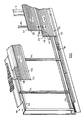
- FIGURE 1 is a fragmentary exploded perspective view, partly broken away, of part a building embodying the invention,
- FIGURES 2a-c are cross-sectional views showing alternative sections of the purlin of Figure 1,
- FIGURE 3 is a section on the line 3-3 of Figure 1 but showing the panels in their assembled position,
- FIGURE 4 is a perspective view to enlarged scale of the clip of Figures 1 to 3,
- FIGURE 5 is a fragmentary perspective view of part of a wall of another building embodying the invention,
- FIGURE 6 is a cross-section, to an enlarged scale, on the line 6-6 of Figure 5,
- FIGURE 7 is a perspective view of a clip used in the system shown in Figures 5 and 6,
- FIGURE 8 is a perspective view similar to that of Figure 1 but of another embodiment of the invention,
- FIGURE 9 is a front elevation of an alternative clip for use in the embodiment of Figures 1 to 4,
- FIGURE 10 is a front elevation of an alternative clip for the embodiment of Figures 5 to 7, and
- FIGURE 11 is a front elevation of a further alternative form of a clip for the embodiment of Figures 5 to 7.
- Referring to Figure 1, there is shown part of a roof of a building. The roof comprises rafters R, which are conventional and between the rafters extend a plurality of purlins one of which is shown at 10 on which cladding panels 11a-c are supported.
- Each panel 11a - c is of composite construction comprising an
outer skin 12 and aninner skin 13 with a filling of thermally insulatingmaterial 14 therebetween. - In this example the
outer skin 12 comprises a steel sheet, in the present example grade Z35 and is 0.5mm thick although its thickness may lie in the range 0.55 to 0.9mm. The sheet is coated with a PVC plastisol but may be coated with any other desired decorative and/or protective material such as Zalutite PVF2 or Alu type 2. - If desired the outer skin may be made of other steel and be of different thicknesses or may be made of other material such as aluminium for example aluminium sheet grade E 3105, 0.9mm thick but may be made of other aluminium grade such as H25 or H8 and other thicknesses. In the present example the sheet is stucco to embossed but it may be provided with a mill finish particularly where it is of H8 grade or be provided with a coating of
Duralcote - The inner sheet is made of steel, in the present example grade Z2, and is 0.25mm thick but may lie in the range 0.25 to 0.5mm, the exposed surface of the sheet is coated with white polyester.
- If desired the inner skin may be made of other steel to that described above i.e. different grade and/or different thickness coated with other decorative and/or protective finish. Alternatively, the inner skin may be made of other material such as aluminium for example E3105 grade and 0.6mm thick although it may be made of other thickness and of other grades of aluminium such as H25.
- In the present example the exposed surface is coated with Duralcote 5 but may be coated with any other suitable protective and/or decorative finish.
- The thermal insulating material in the present example is a conventional polyurethane foam material and is self bonded to the inner and outer skins during the manufacturing process.
- As best shown in Figure 1 the
outer skin 12 is provided with a plurality of upstanding corrugations arranged in two sets. One set comprises thecorrugations 15 whilst the other set comprises thecorrugations corrugation corrugations 15 between each pair ofcorrugations 16 their may be three or, one or more than three. - The
corrugations 16′ at each of twoopposite sides 18, 19 of the panel differ from thecorrugation 16 in that they each have a shape corresponding to one half of thecentral corrugation 16. Thus, when adjacent panels are assembled together the part corrugations 16′ at thesides 18, 19 of each panel combine together to simulate a corrugation similar to thecentral corrugation 16 as is best shown at 20 in Figure 1. - The inner skin is also provided with corrugations as shown in Figure 1 and these corrugations may vary as desired.
- If desired instead of providing a
purlin 10 of the generally sigma configuration shown in Figure 1 the purlins may be of any other desired suitable configuration such as the sections shown in Figures 2a to 2c where, respectively a Zeta or Z Section, a Hot Rolled Channel Section and on I Section as illustrated. - Referring now particularly to Figures 1 and 3, at the
opposite sides 18, 19 of each panel 11a - 11c are provided first and secondstanding seam portions 20a, 20b respectively. - Each such standing seam portion is the same and comprises a generally inverted channel configuration having a first limb 21a, 21b which extends perpendicular to a plane P containing the surface of the parts 17 of the panel and hereinafter referred to as the general plane P of the panel. This first limb 21a, 21b is connected by an integral rolled over
base portion 22a, 22b to a second limb 23a, 23b which extends downwardly and outwardly and has an inwardly and upwardly rolledportion 24a, 24b at the free end thereof. This rolled overportion 24a, 24b provides an abutment part of the associated standing seam portion. A battencap 26 of generally inverted channel configuration is clipped over the adjacent standing seam portions to provide a joint there between and suitable sealant such as non-setting butyl or other suitable sealant is provided within the batten cap to weatherproof the joint. - The batten
cap 26 has downwardly and outwardly extendinglimbs 27 at the lower free ends of which are provided inwardly extending flanges which provide an abutment part for engagement with the abutment parts provided by theportions 24a, 24b to retain the batten cap from displacement away from the general plane P described hereinbefore. - The panels are secured to the
support member 10 by a clip means 30 comprising aclip 31. Theclip 31 comprises anattachment part 32 which is attached to thesupport member 10 by any suitable means, in the present case by self drilling and tappingscrews 32′. Integral with theattachment part 32 is an upstanding part 33 which is received between thesides 18,19. - At the other end of the upstanding part 33 is a panel engagable part 34 having a plurality, in the present example four, of pairs of oppositely directed
hook portions hook part hook parts seam parts 20a, 20b respectively and so serve to restrain the outer skin of thepanels 11a, 11b from movement away from thesupport member 10. - The panel engagable part 34 and the upstanding part 33 are of the same longitudinal extent and are of greater longitudinal extent than is the
attachment part 32. In the present example, theattachment part 32 is 70mm long whilst the upstanding part 33 and panel engagable part 34 are 200mm long. The relatively longer extent of panel engagable part 34 ensures that the restraining load is distributed over a relatively large area of panel whilst the attachment part is made of a length which is related to the width of the support member so as to minimise the amount of material in the attachment part 34. For example, the longitudinal extent of the attachment part may be such that it is not longer than the longitudinal extent of the part of the support member to which the attachment part is attached. The relatively great longitudinally extent of the panel engagable part 34 is particularly beneficial when the panel is likely to be exposed to significant wind uplift conditions where a panel is being pulled away from the support member. By providing clips of the configuration described hereinbefore the panels are securely attached to the support member since the attachment load is spread more evenly throughout the length of the panels by providing the relatively longer panel engagable parts than would be achieved with panel engagable parts of the same longitudinal extent as the associated part of the support member. - If desired the panel engagable part 203 may be of a different longitudinal extent to that described above, for example, they may be shorter, for example, 150mm, or longer if it is desired to spread the load over a still greater area of the panels.
- The batten
cap 26 is of such dimensions as to accommodate thehook parts - The upstanding part 33 may be provided with two oppositely directed transversely extending
tongue parts foam plastics material 14 above inturned, outwardly facing,parts 39, 40 of theinner skin 13 so as to restrain displacement of the inner skin away from thesupport member 10. If desired a plurality of sets of oppositely directed transversely extending tongue portions may be provided instead of two single tongue portions. The relatively great longitudinal extent of the upstanding part 33 ensures the relatively great longitudinal extent of the, or each set, of transversely extending tongue portions so that the restraining force imposed thereby on theinner skin 13 is similarly spread over a relatively great area thereof. Thetongue parts rectangular opening 42 in the upstanding part. If desired thetongue part - The
inner skin 13 is provided withrebate parts 41 to accommodate theattachment part 32 and attachment means 32′. - The further part and a portion of the upstanding part are preferably coated in a thermally insulating plastics material which comprises in the present example and which may comprise a P.V.C. The coating is applied by dip coating but may be applied by any other suitable process such as spraying or painting.
- In the present example the coating is 0.5mm thick but may be of other thickness suitable to give a desired amount of thermal insulation dependent upon the nature of the plastics material. In the present example the plastics material extends over approximately half of the extent of the upstanding portion from the further portion towards the attachment portion. In the present example the clip is 85mm high for a nominally 37mm thick panel and the plastics material extends down the upstanding portion to a distance of 25mm from the upper end of the further portion. If desired, depending upon the overall thickness of the panels the clip may be higher, for example 107mm or 127mm high, for a nominally 60mm or 80mm thick panel respectively and the plastics material may extend for 25mm from the upper end of the further portion.
- The clip may be of other dimensions and the plastics material may in all cases extend over a different extent of the clip than is described hereinbefore. The minimum extent of coverage being governed by the overall panel thickness.
- Referring now to Figure 9 there is shown an alternative form of
means 330 comprising aclip 331 similar to that shown in Figure 4 having anattachment part 332 of the same longitudinal extent as theattachment part 32 shown in Figure 4 but having an upstanding part 333 and panelengagable part 334 of greater longitudinal extent which in this example are 300mm long. In addition, the upstanding part 333 is provided with four generallyrectangular openings 342 and in this embodiment there are no tongue parts corresponding to thetongue parts - Referring now to Figure 5, part of a
building 110 is shown which has a frame which comprisesvertical stanchions 111 carrying upper and lower structuralchannel section members structural members bottom sheeting rail 115 is provided at the foot of thestanchions 111 and vertical sheeting rails 114. The sheeting rails 114, 115 may be of any suitable configuration that are preferably of a "sigma" configuration as shown in the drawings. - The sheeting rails 114 and 115 carry a plurality of wall panels portions of three of which are illustrated in Figure 1 at 116a, 116b and 116c. In this example each panel 116a - 116c extends for the full width of the wall but, if desired, may extend for only part of the length of the wall adjacent side edge faces being abutted and provided with suitable sealing and trim means.
- Each panel 116a - 116c comprises an
outer skin 117 and aninner skin 118 with a filling 119 of thermally insulating material therebetween. The panels may be of the same materials as in the previously described embodiment. Oneedge 120 of each sheet has atongue part 121 projecting therefrom whilst theopposite edge 122 of each sheet has agroove part 123 provided therein. As best shown in Figure 6 theouter skin 117 is formed to provide thetongue part 121 andgroove part 123. The tongue and groove parts are generally "U" shaped in cross-section and thebase 124 provides the outer most part of thetongue part 121 whilst thebase 125 provides the inner most part of thegroove part 123. One limb 126 of the "U" of thetongue 121 is formed integrally with the remainder of theouter skin 117 whilst onelimb 127 of the "U" of the groove is likewise formed integrally with the remainder of theouter skin 117. - The
inner skin 118 is formed with arebate portion 128 adjacent theedges - The
tongue part 121 of one panel, for example, panel 116a is received within thegroove part 123 of the adjacent panel, for example, 116b so that the tongue and groove parts are inter-engaged in the sense of being juxtaposed with the tongue part within the groove part. - In order to attach the panels to the vertical sheeting rolls 114 a plurality of
clips 130 are provided, see Figures 6 and 7, which hold the panels to the sheeting rails by virtue of engagement with the outer sheet 17. - Each
clip 130 comprises anattachment part 131 for attachment to asheeting rail 114 and apanel engagable part 132 for reception between theinter-engaged tongue part 121 andgroove part 123. The panel engagablepart 132 is generally "U" shaped in cross-section and is thus sandwiched between the "U" shapedtongue part 121 and "U" shapedgroove part 123. One limb 33 of thepanel engaging part 132 at the end thereof distant from thebase 134 of the "U" is connected to theattachment part 131 of the clip by connectingpart 135 which extends transversely to the "U" shapedpanel engaging part 132 and hence transversely to the general plane of the panels 116a - 116b. One end of the connectingpart 135 is, therefore, connected to thelimb 133 and the other to theattachment part 131 and is so connected by virtue of being formed integrally therewith. - The panel engagable
part 132 is provided with means to accommodate variation in the clearance between thetongue part 121 andgroove part 123 arising, for example, as a result of tolerances in manufacture of the panels. This means comprises one lug means comprising threelugs 140 pressed out of theother limb 136 to thelimb 133 and extending inwardly towards thetongue part 121 and thebase 134 of the "U". The lug means also comprise another lug means comprising threelugs 141 pressed out of the onelimb 133 and extending outwardly away from thebase 134 and towards thegroove part 123. Thelugs tongue part 121 andgroove part 123. For instance, if the tolerance is less than the extent to which the lugs project the lugs as appropriate, may be elastically deformed towards their associated limb. - If desired the
lugs 140, 141 (or other means to accommodate variation in the clearance between thetongue part 121 andgroove part 123,) may be plastically deformable as well as, or possibly instead of, being elastically deformable. - It will be appreciated that their angle of inclination is such that relative movement between the
lugs 141 and thegroove part 123 in the direction to disengage the connection tend to cause the free edge of thelugs 141 to dig into the wall of thegroove part 123 whilst similarly relative movement between thelugs 140 and thetongue part 121 likewise tends to cause the edge of thelugs 140 to dig into thewall 121. - The
attachment part 131 is connected to its associatedsheeting rail 114 by screw threadedfasteners 154. If desired, however, the attachment means 131 may be connected to the building frame by other means, for example, by being appropriately dimensioned and arranged to be received in a slot provided by a "U" shaped bracket attached to a sheeting rail or by being provided with a hook portion to hook onto a lip of a sheeting rail. - The panel engagable
part 132 is of greater longitudinal extent than is theattachment part 131 e.g. 200mm and 70mm respectively whilst the connectingpart 135 is of truncated triangular configuration so as to increase in longitudinal extent from the end thereof connected to the attachment part towards the end thereof connected to the panel engagable part. The relatively long extent of the panel engagablepart 132 ensures that the restraining load is distributed over a relatively large area of the panel whilst theattachment part 131 is made of a length which is related to the width of the support member so as to minimise the amount of material in the attachment part. For example, the attachment part may be made such that it is not longer than the width extent of the part of the support member to which the attachment part is attached. Such clip configuration is particularly suitable when the panel is likely to be exposed to significant wind uplift conditions where a panel is being pulled away from the support member. By providing clips of the configuration as shown in Figure 7 the panels are securely attached to the support member since the attachment load is spread more evenly throughout the length of the panels by providing the relatively longer panel engagable parts than would be achieved with panel engagable parts of the same longitudinal extent as the associated part of the support member. - If desired the panel engagable
part 132 may be of a different longitudinal extent to that described above, for example, it may be shorter,for example 150mm, or longer if desired to spread the load over a greater area of the panels. - Figure 10 shows an example of an alternative form of clip means 430 comprising
clip 431 having apanel engagable part 434 of greater longitudinal extent than the clip shown in Figure 7. In Figure 10 the panel engagablepart 434 is 300mm long whilst theattachment part 432 is of the same extent as that shown in Figure 7. - The bottom edge of the panel 116a is connected to the
bottom sheeting rail 13 by means of aclip 160 which is similar to theclip 130 described hereinbefore except for the configuration of the attachment means which as best shown in Figure 5, extends from the connectingpart 135 on the same side thereof as thepanel engaging part 132 and is provided with openings through which screw threaded fasteners pass to attach theclip 160 to thebottom sheeting rail 113. Theclip 160 is preferably unprovided with clearance variation accomodating lugs, or other means, for economy since there is no tongue part engaged with the groove part of the bottom edge of the panel 16a. - Figure 11 shows a clip 531 having a
panel engagable part 534 of the same size as that shown in Figure 10 but adapted for connection of the bottom edge of the panel 116a. It will be seen that in this example theattachment part 532 is of the same longitudinal extent as the panel engagablepart 534 and connectingpart 533. To permit of access toapertures 532a through which screw threaded fasteners pass to attach the clip to thebottom sheeting rail 113slots 550 are provided in the panel engagablepart 534. - Referring now to Figure 8 there is shown a modification of the invention in which the cladding panels indicated at 216a - 216d extend with their longest edges vertical. These edges are configured in exactly the same way as the
longitudinal edges clips - In all other respects the clips inter-engagement with the panels is as in the previously described embodiment.
- Both the "horizontal" cladding panels shown in Figure 5 to 7 and the "vertical" cladding panels shown in Figure 8 are secured to the upper channel section member, or eaves beam, 12 with conventional through - fixing self drilling and tapping screws which are subsequently hidden behind a gutter or a flashing. If desired other securing means may be provided. Where the panels are vertical panels clip means may be provided thereby avoiding the use of through-fixings altogether.
- In all embodiments panel engagable part may have the length lying in the range of approximately 150 to 300mm or 150 to 200mm whilst the attachment part has the length lying in the range of 50 to 70mm.
- Irrespective of the dimensions mentioned in the preceding paragraph the ratio of the length of the panel engagable part to the length of the attachment part may lie in the ratio 2:1 to 6:1, or 2:1 to 4:1.
- If desired, the panels may be of other construction to that described hereinbefore and the tongue and groove part may be provided in other ways than by the outer skin.
- The features disclosed in the foregoing description, or the accompanying drawing, expressed in their specific forms or in terms of a means for performing the disclosed function, or a metal or process for attaining the disclosed result, or a class or group of substances or compositions, as appropriate, may, separately or any combination of such features, be utilised for realising the invention in diverse forms thereof.
Claims (14)
- A building cladding system comprising an elongate support member (10, 114), a plurality of cladding panels (11a - c, 116a - c) attached to the support member (10, 114) of a building by clip means (30, 130) the clip means comprising a clip (31, 130) having an attachment part (32, 131) attached to the support member (10, 114) by attachment means (32', 154) and a panel engageable part (24, 132) having a surface engaged with the panel (11a - c, 116a - c) to attach the panel to the support member (10, 114), each panel (11a - c, 116a - c) comprises an outer skin (12, 117) and an inner skin (13, 118) with a filling (14, 119) of thermally insulating material therebetween, and the panel engageable part (34,132) of the clip having a dimension, perpendicular to the longitudinal extent of the support member (10,114), which is greater than the width of the part of the support member to which the attachment part (32,131) is attached, characterised in that the attachment part (32,132) is attached to one surface of the support member (10,114) and said dimension of the panel engageable part (34,132) of the clip is greater than a similarly orientated dimension of the attachment part (32,132) of the clip whilst said dimension of the attachment part (32,131) is not greater than said width of said part of the support member (10,114).
- A system according to Claim 1 wherein the panel engageable part (34, 132) is between 150 and 300mm long.
- A system according to Claim 1 or Claim 2 wherein the ratio of the length of the panel engageable part (34, 132) to the attachment part (32, 131) lies in the range 2:1 to 6:1.
- A system according to any one of the preceding claims wherein the outer skin (12) has at each of two opposite sides thereof (18, 19) upstanding first and second seam portions (20a, 20b) respectively, the first and second seam portions of adjacent panels comprising a joint between the panels.
- A system according to Claim 4 wherein the panel engageable part (34) is adapted for engagement with at least one of the first and second seam portions (20a, 20b) to restrain movement of the or each seam portion (20a, 20b) of the standing seam and hence of the panel (11a - c) away from the support member (10).
- A system according to Claim 5 wherein the clip (31) comprises an upstanding part (33) which extends generally normally to the support member (10) and to the general plane of the panel (11a - c) and having at its upper end at least one hook part (35, 36) adapted to hook over at least one seam portion (20a, 20b).
- A system according to any one of Claims 4 to 6 wherein at least a part of the clip means (30) comprises a thermal break.
- A system according to Claim 7 wherein the thermal break comprises a layer of thermally insulating material provided on at least the surface of the clip (31) which engage the first and/or second seam portions (20a, 20b).
- A system according to any one of the preceding claims wherein one edge (120) of each panel has a tongue part 121 and the opposite edge 122 of each panel has a groove part (123), the tongue part (121) of one panel being receivable in the groove part (123) of an adjacent panel so as to be juxtaposed and the panel engageable part (132) of the clip (130) being adapted for reception between juxtaposed tongue and groove.
- A system according to Claim 9 wherein the panel engageable part (132) of the clip (130) is generally "U" shape in cross section and is adapted to be sandwiched between a juxtaposed "U" shaped tongue and groove.
- A system according to Claim 9 or Claim 10 wherein the panel engageable part (132) has means (140,141) to accommodate variation in the clearance between the juxtaposed tongue and groove parts between which it is sandwiched.
- A system according to Claim 11 wherein the means comprises displaceable portions (140, 141) of the panel engageable part (132) which are displaceable so as to accommodate said variation in effective thickness.
- A system according to Claim 12 wherein the displaceable portions comprise at least one lug means (140, 141) projecting from the clip towards the associated panel tongue and/or groove part.
- A system according to Claim 13 wherein one lug means (140) extends from the inside surface of the "U" shaped panel engageable part for engagement with the tongue part (121) and another lug means (141) extends from the outer surface of the "U" shaped panel engageable part for engagement with the groove part (123).
Priority Applications (1)
| Application Number | Priority Date | Filing Date | Title |
|---|---|---|---|
| EP19880105398 EP0311738B1 (en) | 1987-10-16 | 1988-04-05 | Building cladding system |
Applications Claiming Priority (3)
| Application Number | Priority Date | Filing Date | Title |
|---|---|---|---|
| GB878724304A GB8724304D0 (en) | 1987-10-16 | 1987-10-16 | Building cladding system |
| GB8724304 | 1987-10-16 | ||
| EP19880105398 EP0311738B1 (en) | 1987-10-16 | 1988-04-05 | Building cladding system |
Publications (2)
| Publication Number | Publication Date |
|---|---|
| EP0311738A1 EP0311738A1 (en) | 1989-04-19 |
| EP0311738B1 true EP0311738B1 (en) | 1993-03-31 |
Family
ID=26113853
Family Applications (1)
| Application Number | Title | Priority Date | Filing Date |
|---|---|---|---|
| EP19880105398 Expired - Lifetime EP0311738B1 (en) | 1987-10-16 | 1988-04-05 | Building cladding system |
Country Status (1)
| Country | Link |
|---|---|
| EP (1) | EP0311738B1 (en) |
Families Citing this family (3)
| Publication number | Priority date | Publication date | Assignee | Title |
|---|---|---|---|---|
| US5394672A (en) * | 1993-07-26 | 1995-03-07 | Insulok Corp. | Interlocking insulated roof panel system |
| WO1997038186A1 (en) * | 1996-04-10 | 1997-10-16 | Goodings Peter J | Apparatus and method of installation of a composite building panel |
| US8769901B2 (en) | 2010-05-28 | 2014-07-08 | The Diller Corporation | Cladding system for building laminates |
Family Cites Families (10)
| Publication number | Priority date | Publication date | Assignee | Title |
|---|---|---|---|---|
| DE1684093A1 (en) * | 1967-08-21 | 1971-04-01 | Gottfried Welzel | Construction element mainly made of ceramic for interior and exterior wall facing of buildings and for ceramic floors |
| US3511011A (en) * | 1968-12-03 | 1970-05-12 | Reynolds Metals Co | Metal panel and building construction using same |
| AT337427B (en) * | 1974-10-31 | 1977-06-27 | Waibel Rudolf | FASTENING ELEMENT |
| US4102105A (en) * | 1975-05-29 | 1978-07-25 | Armco Steel Corporation | Interlocked channel section panels and connectors therefor |
| US3998019A (en) * | 1975-08-18 | 1976-12-21 | Illinois Tool Works Inc. | Roof panel fastener and joint construction |
| US4123885A (en) * | 1976-04-30 | 1978-11-07 | Cyclops Corporation | Building panel joint |
| US4269012A (en) * | 1979-02-01 | 1981-05-26 | The Binkley Company | Standing seam roof, panel therefor, and method of installation |
| US4361998A (en) * | 1979-07-12 | 1982-12-07 | Atlantic Building Systems, Inc. | Standing seam roof system |
| US4538391A (en) * | 1981-07-27 | 1985-09-03 | Chicago Metallic Corporation | Metal building panels for wall applications |
| DE3307991A1 (en) * | 1983-03-07 | 1984-09-13 | Isotec AG, Zug | THERMAL INSULATING CLADDING ELEMENT FOR WALL AND CEILING |
-
1988
- 1988-04-05 EP EP19880105398 patent/EP0311738B1/en not_active Expired - Lifetime
Also Published As
| Publication number | Publication date |
|---|---|
| EP0311738A1 (en) | 1989-04-19 |
Similar Documents
| Publication | Publication Date | Title |
|---|---|---|
| US6000178A (en) | Apparatus and method of installation of a composite building panel | |
| US4184301A (en) | Fastening device for wall panel joints | |
| US4373312A (en) | Prefabricated panel construction system | |
| US20080000176A1 (en) | Insulated panel system | |
| US4283897A (en) | Snap action panel wall construction | |
| FI60054C (en) | YTTERVAEGG- ELLER TAKKEKLAADAD | |
| US4135342A (en) | Insulated metal roofing and siding system | |
| US5181360A (en) | Standing-seam roof panel system | |
| US4133161A (en) | Panel assemblies and methods of forming same | |
| US5001881A (en) | Sheet cladded roof assembly and cleat arrangement | |
| US4476658A (en) | Standing seam roof system | |
| US5735084A (en) | Fascia-soffit combination | |
| US5048248A (en) | Non-directional composite foam panel side joint | |
| US4248021A (en) | Support means for wall or roof structure | |
| US4583339A (en) | Roofing and siding system | |
| EP0311737A2 (en) | Building cladding system | |
| EP0311738B1 (en) | Building cladding system | |
| US5438810A (en) | Roofing panels and roofing assemblies thereof | |
| US6272807B1 (en) | Rain directional panel | |
| US3253376A (en) | Panel constructions and the like | |
| GB2200670A (en) | Thermal insulation roof or wall panel | |
| WO2000023673A1 (en) | Roof and wall sheeting system | |
| US5272849A (en) | Roof covering system | |
| EP0504505A1 (en) | Wall/roof assemblies | |
| EP0286052B1 (en) | Building cladding system |
Legal Events
| Date | Code | Title | Description |
|---|---|---|---|
| PUAI | Public reference made under article 153(3) epc to a published international application that has entered the european phase |
Free format text: ORIGINAL CODE: 0009012 |
|
| AK | Designated contracting states |
Kind code of ref document: A1 Designated state(s): BE DE FR GB LU NL |
|
| 17P | Request for examination filed |
Effective date: 19890626 |
|
| 17Q | First examination report despatched |
Effective date: 19900814 |
|
| GRAA | (expected) grant |
Free format text: ORIGINAL CODE: 0009210 |
|
| RAP1 | Party data changed (applicant data changed or rights of an application transferred) |
Owner name: WARD BUILDING SYSTEMS LIMITED |
|
| AK | Designated contracting states |
Kind code of ref document: B1 Designated state(s): BE DE FR GB LU NL |
|
| PG25 | Lapsed in a contracting state [announced via postgrant information from national office to epo] |
Ref country code: NL Effective date: 19930331 |
|
| PG25 | Lapsed in a contracting state [announced via postgrant information from national office to epo] |
Ref country code: LU Free format text: LAPSE BECAUSE OF NON-PAYMENT OF DUE FEES Effective date: 19930430 |
|
| REF | Corresponds to: |
Ref document number: 3879846 Country of ref document: DE Date of ref document: 19930506 |
|
| ET | Fr: translation filed | ||
| NLV1 | Nl: lapsed or annulled due to failure to fulfill the requirements of art. 29p and 29m of the patents act | ||
| PLBE | No opposition filed within time limit |
Free format text: ORIGINAL CODE: 0009261 |
|
| STAA | Information on the status of an ep patent application or granted ep patent |
Free format text: STATUS: NO OPPOSITION FILED WITHIN TIME LIMIT |
|
| 26N | No opposition filed | ||
| PGFP | Annual fee paid to national office [announced via postgrant information from national office to epo] |
Ref country code: GB Payment date: 19950328 Year of fee payment: 8 |
|
| PGFP | Annual fee paid to national office [announced via postgrant information from national office to epo] |
Ref country code: DE Payment date: 19950410 Year of fee payment: 8 |
|
| PGFP | Annual fee paid to national office [announced via postgrant information from national office to epo] |
Ref country code: FR Payment date: 19950411 Year of fee payment: 8 |
|
| PGFP | Annual fee paid to national office [announced via postgrant information from national office to epo] |
Ref country code: BE Payment date: 19950510 Year of fee payment: 8 |
|
| PG25 | Lapsed in a contracting state [announced via postgrant information from national office to epo] |
Ref country code: GB Effective date: 19960405 |
|
| PG25 | Lapsed in a contracting state [announced via postgrant information from national office to epo] |
Ref country code: BE Effective date: 19960430 |
|
| BERE | Be: lapsed |
Owner name: WARD BUILDING SYSTEMS LTD Effective date: 19960430 |
|
| GBPC | Gb: european patent ceased through non-payment of renewal fee |
Effective date: 19960405 |
|
| PG25 | Lapsed in a contracting state [announced via postgrant information from national office to epo] |
Ref country code: FR Effective date: 19961227 |
|
| PG25 | Lapsed in a contracting state [announced via postgrant information from national office to epo] |
Ref country code: DE Effective date: 19970101 |
|
| REG | Reference to a national code |
Ref country code: FR Ref legal event code: ST |