EP0311409A1 - Arrangement for continuous mixing of fluids - Google Patents
Arrangement for continuous mixing of fluids Download PDFInfo
- Publication number
- EP0311409A1 EP0311409A1 EP88309335A EP88309335A EP0311409A1 EP 0311409 A1 EP0311409 A1 EP 0311409A1 EP 88309335 A EP88309335 A EP 88309335A EP 88309335 A EP88309335 A EP 88309335A EP 0311409 A1 EP0311409 A1 EP 0311409A1
- Authority
- EP
- European Patent Office
- Prior art keywords
- insert
- extensions
- helical
- conduit
- inserts
- Prior art date
- Legal status (The legal status is an assumption and is not a legal conclusion. Google has not performed a legal analysis and makes no representation as to the accuracy of the status listed.)
- Withdrawn
Links
Images

Classifications
-
- B—PERFORMING OPERATIONS; TRANSPORTING
- B01—PHYSICAL OR CHEMICAL PROCESSES OR APPARATUS IN GENERAL
- B01F—MIXING, e.g. DISSOLVING, EMULSIFYING OR DISPERSING
- B01F25/00—Flow mixers; Mixers for falling materials, e.g. solid particles
- B01F25/40—Static mixers
- B01F25/42—Static mixers in which the mixing is affected by moving the components jointly in changing directions, e.g. in tubes provided with baffles or obstructions
- B01F25/43—Mixing tubes, e.g. wherein the material is moved in a radial or partly reversed direction
- B01F25/431—Straight mixing tubes with baffles or obstructions that do not cause substantial pressure drop; Baffles therefor
- B01F25/4314—Straight mixing tubes with baffles or obstructions that do not cause substantial pressure drop; Baffles therefor with helical baffles
Landscapes
- Chemical & Material Sciences (AREA)
- Dispersion Chemistry (AREA)
- Chemical Kinetics & Catalysis (AREA)
Abstract
Arrangement comprises a number of inserts (1) with helical surfaces within a conduit (6), said inserts having at their inlet the shape of a polygon, from which extend helical extensions (12-14) which are in contact with each other at their inlets and also at their outlets or at points between their inlets and outlets.
Description
- The invention relates to an arrangement for the mixing of fluids, the arrangment comprising a number of inserts with helical surfaces, the inlet edges of which form a polygon, the inserts being situated in a conduit where they are arranged in a row. The arrangement is designed for the homogenization of miscible liquids which are viscous and low viscous, for the dispersion of liquids and gases in liquids, for the intensification of heat transfer during the flow of liquids, for the creation of a suitable interphase surface in heterongenous reactions, for emulgation, for part-mixing and the like.
- Presently used arrangements for continuous mixing of fluids use various kinds of elements built in conduits. Said built in elements have the shape of various helical surfaces, suitably situated and shaped blades or vanes, channels crossing each other, shaped plates and the like.
- A drawback of mixing arrangements with blades, vanes and channels is that they cause high pressure losses and have a tendency for clogging. A drawback of mixing arrangements with helical surfaces is their relatively large length required for thorough mixing and mostly also reduced mixing efficiency in the course of transitional hydrodynamic conditions.
- It is an object of this invention to provide a continuous mixing arrangement for fluids, the arrangement comprising helical inserts in a conduit which is of reasonable length and ensures a very intensive mixing with low pressure losses.
- An arrangement according to this invention comprises a number of inserts with helical surfaces arranged in a row in a conduit, the inlet part of each insert forming a polygon from which helical extensions extend, said helical extensions being in mutual contact at their inlets and also additionally at the outlet of the insert or at a point between the inlet and outlet. The width of the developed extensions can differ along their length; it can be larger or smaller than the length of a side of the polygon. Gaps are thus formed between the individual helical extensions, the total through flow area of said gaps being 0.2 to 3 times the area of the polygon at the inlet end of the insert. The longitudinal edges of said extensions which are closer to the internal surface of the conduit pointing advantageously toward the corners of the polygon of the following insert.
- The main advantage of an arrangement according to this invention is that it enables an intensive mixing of both viscous and low viscous liquids, the emulgation and dispersion of gases into liquids and part-mixing while maintaining a reasonable length of the whole arrangement with low pressure losses.
- An arrangement according to this invention will now be described, by way of example, with reference to the accompanying diagrammatic drawings, in which:
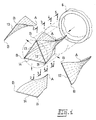
- Figure 1 is an exploded axonometric view of an insert with a triangular base outside of its conduit, individual helical extensions being shown in addition separately,
- Figures 2 to 5 are cross-sectional views of an insert within its conduit, the sections being taken consecutively along transverse planes indicated in Fig.1 by lines 2 - 2, 3 - 3, 4 - 4 and 5 - 5,
- Figure 6 is an axonometric view of an insert as viewed from the outlet, where the helical extensions are interconnected at their outlets,
- Figure 7 is a similar view of an insert where the helical extensions are interconnected at a point upstream of their outlet, and
- Figures 8 and 9 are sectional views of an insert within its conduit where the helical extensions are interconnected at a point spaced from the outlet, the sections being taken along transverse planes, indicated in Fig.7 by lines 8 - 8 and 9 - 9.
- Fig.1 shows an arrangement which comprises an insert 1 adapted to be inserted into a
conduit 6. This insert 1 is composed of three identical helical surfaces which are interconnected at the ends of their inlet edges at points B so that these inlet edges form a polygon, in the illustrated example an equilateral triangle, said helicalsurfaces forming extensions conduit 6 into which it is to be inserted. In order to make the shape of the helical surfaces forming saidextensions helical extensions helical extensions helical extensions conduit 6. Gaps are thus formed between the individual extensions, the size of the gaps depending on the shape of the extensions which in the embodiment shown in Fig.1 is a quadrilateral with the length of the base equal to √3/2 of the internal diameter of theconduit 6 and with the length of the top edge equal to one half of this diameter. - The lateral edges of the
helical inserts 12 13, 14 can be straight or curved in order to obtain a suitable area of said gaps most convenient for the viscosity of the ingredients to be mixed. One lateral edge of each helical extension remains always close to the internal surface of theconduit 6. - The helical insert 1 of Fig.1 is right-handed and its pitch is about four times the length of the insert 1, whereby the axis of the helical surface of the extension divides in half the width of the extension at the inlet and outlet.
- If the inserts 1 are arranged in a row in the
conduit 6, it is possible to alternate inserts 1 with a right-hand or left-hand helix either individually or in groups of say 2 to 15 inserts, advantageously so that the ends of the longitudinal edges of the helical extensions 1 which are close to the internal surface of theconduit 6 point toward the corners of the inlet polygon of the following insert 1. If the inserts 1 are used in tubes with a larger diameter, the inserts 1 can be arranged in the same positions, without being angularly displaced with respect to each other. Thus the mutual position of the inserts 1 can easily be maintained. The inserts 1 are in this case (for a triangular base) displaced through 60°. By alternating inserts 1 with right-hand and left-hand helixes, the torque transmitted to the arrangement by the throughflowing liquid is equalized. - Figs. 2 to 5 show cross-sections of the insert 1 of Fig.1, the individual sections being taken at different distances along the length of the insert 1 as indicated in Fig.1 by lines 2 - 2, 3 - 3, 4 - 4 and 5 - 5. In fact, Fig.2 can be considered to be the front elevation and Fig.5 the rear elevation of the insert 1. Fig.2 shows the basic polygon (triangle) at the inlet end and the section in Fig.5 conditions at the outlet end of the insert 1. The media flowing along such an insert are thereby thoroughly mixed. The part of the fluid flowing between the internal surface of the
conduit 6 and theextensions extensions - Fig. 6 is an axonometric view of an insert viewed from the outlet end thereof and showing the outlet ends of the lateral edges of the
helical extensions - Fig. 7 shows an alternative arrangement of an insert 1 where the internal lateral edges of
extensions individual extensions - Figs. 8 and 9 show sectional views of the last mentioned arrangement taken along planes. indicated in Fig. 7 by lines 8 - 8 and 9 - 9, in a way similar to the sectional views in Fig.2 to 5. A different penetration of the two component parts being mixed together is obvious therefrom.
- An arrangement according to the invention operates as follows. The liquid or the mixture passing through the
conduit 6 is at the end of each insert 1 divided into a number of streams corresponding to the number ofhelical extensions conduit 6. The liquid flowing inside the insert 1 is forced to pass through gaps between individualhelical extensions conduit 6 takes place. As said gaps can be made to be of different cross-section, variations of amounts of throughflowing liquid and variations of the speed of flow can be achieved as is to a certain degree visible from the sectional views in Fig.2 to 5 and 8 and 9. When the liquid leaving the insert 1 enters the following insert 1, a further division of the streams takes place. - By the division of streams at the inlet of the inserts 1 and by mutual penetration of the streams in the course of passage through an insert 1 an intensive mixing takes place if the gaps are of suitable sizes.
- A further intensification of mixing, particularly of the part of the liquid in the central part of the insert 1 in the axis of the
conduit 6 which is less guided by thehelical extensions - The inserts 1 are preferably made of a material which is not subject to corrosion by the mixed components, particularly of plastics, by any of the commonly known processes.
- The arrangement according to this invention can be used particularly for the homogenization ofmiscible liquids, for the dispersion of liquids and of gases in liquids, for the intensification of heat transmission of flowing liquids, for the creation of a suitable interphase surface in heterogenous reactions, for emulgation, for partial mixing and the like.
- The arrangement shows a very low pressure loss, particularly in the turbulent range and very good homogenization effects, as the homogenization takes place not only by division of the streams at the inlet edges of the element, as is common with helical mixers, but also during the passage of the liquid through the element. The mixer requires relatively low amounts of power for homogenization compared with presently used mixers. It also shows no loss of efficiency of homogenization within the range of Reynolds number Re 10 to 300 as other known mixers.
Claims (5)
1. Arrangement for continuous mixing of fluids, the arrangement comprising a number of inserts arranged in a row in a conduit, the inlet part of each insert forming a polygon from which extend helical extensions, characterised in that the helical extensions (12, 13, 14) of each said insert (1) are in mutual contact at their inlets and within a distance from 0,5 to one times the length of the insert therefrom, the width of the helical extensions varying along their length, gaps being formed between individual extensions, the overall throughflow area of the gaps of each said insert amounting to 0.2 to 3 times the area of the polygon at the inlet of the insert.
2. Arrangement according to claim 1 characterised in that the pitch of the helical surfaces of the extensions of each said insert is in the same direction and all inserts in the conduit (6) have the same number of said helical extensions.
3. Arrangement according to claim 1 characterised in that said inserts with right hand and left hand helixes of their extensions alternate within the conduit (6) after 1 to 15 inserts.
4. Arrangement according to any one of the preceding claims characterised in that the longitudinal edges of the helical extensions which are close to the internal surface of the conduit at the outlet of one said insert point towards the apexes of the polygonal inlet of the following insert.
5. An apparatus including an arrangement according to any one of the preceding claims.
Applications Claiming Priority (2)
| Application Number | Priority Date | Filing Date | Title |
|---|---|---|---|
| CS877210A CS264468B1 (en) | 1987-10-07 | 1987-10-07 | Apparatus for continuous mixing of liquids |
| CS7210/87 | 1987-10-07 |
Publications (1)
| Publication Number | Publication Date |
|---|---|
| EP0311409A1 true EP0311409A1 (en) | 1989-04-12 |
Family
ID=5420841
Family Applications (1)
| Application Number | Title | Priority Date | Filing Date |
|---|---|---|---|
| EP88309335A Withdrawn EP0311409A1 (en) | 1987-10-07 | 1988-10-06 | Arrangement for continuous mixing of fluids |
Country Status (3)
| Country | Link |
|---|---|
| US (1) | US4874249A (en) |
| EP (1) | EP0311409A1 (en) |
| CS (1) | CS264468B1 (en) |
Cited By (1)
| Publication number | Priority date | Publication date | Assignee | Title |
|---|---|---|---|---|
| US20180099444A1 (en) * | 2016-10-06 | 2018-04-12 | Injection Mold Consulting, LLC | Injection mold insert |
Families Citing this family (12)
| Publication number | Priority date | Publication date | Assignee | Title |
|---|---|---|---|---|
| US6166815A (en) * | 1992-09-02 | 2000-12-26 | Raytheon Company | Constantly high sensitivity fiber optic interferometer sensor |
| US5971603A (en) * | 1998-03-06 | 1999-10-26 | The Madison Group: Polymer Processing Research Corp. | Static mixer head |
| USRE40407E1 (en) | 1999-05-24 | 2008-07-01 | Vortex Flow, Inc. | Method and apparatus for mixing fluids |
| AT408860B (en) * | 1999-12-17 | 2002-03-25 | A & G Extrusion Technology Gmb | METHOD FOR MIXING A MELT FLOW OF PLASTIC |
| US6467949B1 (en) * | 2000-08-02 | 2002-10-22 | Chemineer, Inc. | Static mixer element and method for mixing two fluids |
| WO2005063368A2 (en) * | 2003-12-23 | 2005-07-14 | The Regents Of The University Of Michigan | Method for mixing fluid streams, microfluidic mixer and microfluidic chip utilizing same |
| US8122947B2 (en) * | 2007-11-29 | 2012-02-28 | Saudi Arabian Oil Company | Turbulent device to prevent phase separation |
| US20100110826A1 (en) * | 2008-11-06 | 2010-05-06 | D Herde Eric J | Fractal static mixer |
| CN104560111B (en) | 2013-10-25 | 2017-08-25 | 中国石油化工股份有限公司 | Heat-transfer pipe and use its pyrolysis furnace |
| CN106362608B (en) * | 2016-11-18 | 2019-04-26 | 广西大学 | A kind of cooling mixing tube of chemical industry |
| KR20200028996A (en) * | 2017-07-12 | 2020-03-17 | 노드슨 코포레이션 | Static mixer with triangular mixing conduit |
| US11378110B1 (en) * | 2022-01-05 | 2022-07-05 | Vortex Pipe Systems LLC | Flexible fluid flow modifying device |
Citations (4)
| Publication number | Priority date | Publication date | Assignee | Title |
|---|---|---|---|---|
| US3664638A (en) * | 1970-02-24 | 1972-05-23 | Kenics Corp | Mixing device |
| DE2245442A1 (en) * | 1971-09-17 | 1973-03-29 | Apv Co Ltd | DEVICE TO SUPPORT THE DEVELOPMENT OF TURBULENCE |
| DE2343352A1 (en) * | 1973-08-28 | 1975-03-13 | Worcester Valve Co Ltd | Fluid mixer with helical guide vanes in a pipeline - to subdivide each upstream channel into downstream channels |
| US3949970A (en) * | 1974-01-02 | 1976-04-13 | Gebrs. ter Braak B.V. | Mixer |
Family Cites Families (4)
| Publication number | Priority date | Publication date | Assignee | Title |
|---|---|---|---|---|
| BE754657Q (en) * | 1965-11-29 | 1971-01-18 | Kenics Corp | MIXER APPLIANCE |
| US3827888A (en) * | 1972-03-06 | 1974-08-06 | Eastman Kodak Co | Apparatus and process for combining chemically compatible solutions |
| US4050676A (en) * | 1974-04-19 | 1977-09-27 | Yasushi Morishima | Mixing device and element therefor |
| US4511258A (en) * | 1983-03-25 | 1985-04-16 | Koflo Corporation | Static material mixing apparatus |
-
1987
- 1987-10-07 CS CS877210A patent/CS264468B1/en unknown
-
1988
- 1988-10-06 EP EP88309335A patent/EP0311409A1/en not_active Withdrawn
- 1988-10-07 US US07/254,622 patent/US4874249A/en not_active Expired - Fee Related
Patent Citations (4)
| Publication number | Priority date | Publication date | Assignee | Title |
|---|---|---|---|---|
| US3664638A (en) * | 1970-02-24 | 1972-05-23 | Kenics Corp | Mixing device |
| DE2245442A1 (en) * | 1971-09-17 | 1973-03-29 | Apv Co Ltd | DEVICE TO SUPPORT THE DEVELOPMENT OF TURBULENCE |
| DE2343352A1 (en) * | 1973-08-28 | 1975-03-13 | Worcester Valve Co Ltd | Fluid mixer with helical guide vanes in a pipeline - to subdivide each upstream channel into downstream channels |
| US3949970A (en) * | 1974-01-02 | 1976-04-13 | Gebrs. ter Braak B.V. | Mixer |
Cited By (2)
| Publication number | Priority date | Publication date | Assignee | Title |
|---|---|---|---|---|
| US20180099444A1 (en) * | 2016-10-06 | 2018-04-12 | Injection Mold Consulting, LLC | Injection mold insert |
| US10688703B2 (en) * | 2016-10-06 | 2020-06-23 | Injection Mold Consulting, LLC | Injection mold insert |
Also Published As
| Publication number | Publication date |
|---|---|
| CS264468B1 (en) | 1989-08-14 |
| CS721087A1 (en) | 1988-10-14 |
| US4874249A (en) | 1989-10-17 |
Similar Documents
| Publication | Publication Date | Title |
|---|---|---|
| EP0311409A1 (en) | Arrangement for continuous mixing of fluids | |
| US4408893A (en) | Motionless mixing device | |
| US4179222A (en) | Flow turbulence generating and mixing device | |
| US4643584A (en) | Motionless mixer | |
| EP0360371B1 (en) | Motionless mixers | |
| US4093188A (en) | Static mixer and method of mixing fluids | |
| EP1067352B1 (en) | Heat exchange device | |
| US3664638A (en) | Mixing device | |
| US4164375A (en) | In-line mixer | |
| US20110080801A1 (en) | Static mixing device for flowable substances | |
| US4461579A (en) | Motionless mixer combination | |
| JPS62144738A (en) | Liquid mixer | |
| JPH09901A (en) | Mixer and usage thereof | |
| PL182950B1 (en) | Mixing tube for low-viscosity fluids | |
| EP0412177A1 (en) | Static mixing device | |
| CA2417273C (en) | Static mixer element and method for mixing two fluids | |
| CA1142509A (en) | Static mixer tube with internal triangular element approximations to helices | |
| US4840493A (en) | Motionless mixers and baffles | |
| US4340311A (en) | Interfacial surface generator mixer | |
| JPH09173808A (en) | Mixing device | |
| EP0071454B1 (en) | Static mixers | |
| US7264394B1 (en) | Static device and method of making | |
| US6743006B2 (en) | Die for extruding flowable materials and having a static mixer therein | |
| KR100500843B1 (en) | Multiple static mixer | |
| WO1992014541A1 (en) | Mixing and homogenising apparatus |
Legal Events
| Date | Code | Title | Description |
|---|---|---|---|
| PUAI | Public reference made under article 153(3) epc to a published international application that has entered the european phase |
Free format text: ORIGINAL CODE: 0009012 |
|
| AK | Designated contracting states |
Kind code of ref document: A1 Designated state(s): BE CH DE FR GB IT LI LU NL SE |
|
| 17P | Request for examination filed |
Effective date: 19890807 |
|
| 17Q | First examination report despatched |
Effective date: 19910524 |
|
| STAA | Information on the status of an ep patent application or granted ep patent |
Free format text: STATUS: THE APPLICATION IS DEEMED TO BE WITHDRAWN |
|
| 18D | Application deemed to be withdrawn |
Effective date: 19911203 |