EP0310982A2 - Verfahren zur Vermeidung einer Überhitzung von Hochtemperatur-Speicherbatterien - Google Patents
Verfahren zur Vermeidung einer Überhitzung von Hochtemperatur-Speicherbatterien Download PDFInfo
- Publication number
- EP0310982A2 EP0310982A2 EP88116296A EP88116296A EP0310982A2 EP 0310982 A2 EP0310982 A2 EP 0310982A2 EP 88116296 A EP88116296 A EP 88116296A EP 88116296 A EP88116296 A EP 88116296A EP 0310982 A2 EP0310982 A2 EP 0310982A2
- Authority
- EP
- European Patent Office
- Prior art keywords
- internal temperature
- temperature
- cooling device
- switched
- value
- Prior art date
- Legal status (The legal status is an assumption and is not a legal conclusion. Google has not performed a legal analysis and makes no representation as to the accuracy of the status listed.)
- Granted
Links
- 238000000034 method Methods 0.000 title claims abstract description 13
- 238000013021 overheating Methods 0.000 title claims abstract description 8
- 238000001816 cooling Methods 0.000 claims abstract description 29
- 210000000352 storage cell Anatomy 0.000 abstract description 17
- 210000004027 cell Anatomy 0.000 description 8
- 238000009413 insulation Methods 0.000 description 3
- 238000013459 approach Methods 0.000 description 2
- 230000015572 biosynthetic process Effects 0.000 description 2
- 230000017525 heat dissipation Effects 0.000 description 2
- DGAQECJNVWCQMB-PUAWFVPOSA-M Ilexoside XXIX Chemical compound C[C@@H]1CC[C@@]2(CC[C@@]3(C(=CC[C@H]4[C@]3(CC[C@@H]5[C@@]4(CC[C@@H](C5(C)C)OS(=O)(=O)[O-])C)C)[C@@H]2[C@]1(C)O)C)C(=O)O[C@H]6[C@@H]([C@H]([C@@H]([C@H](O6)CO)O)O)O.[Na+] DGAQECJNVWCQMB-PUAWFVPOSA-M 0.000 description 1
- NINIDFKCEFEMDL-UHFFFAOYSA-N Sulfur Chemical compound [S] NINIDFKCEFEMDL-UHFFFAOYSA-N 0.000 description 1
- 230000005611 electricity Effects 0.000 description 1
- 239000011810 insulating material Substances 0.000 description 1
- 238000005259 measurement Methods 0.000 description 1
- 238000005192 partition Methods 0.000 description 1
- 239000000376 reactant Substances 0.000 description 1
- 239000011734 sodium Substances 0.000 description 1
- 229910052708 sodium Inorganic materials 0.000 description 1
- 239000011593 sulfur Substances 0.000 description 1
- 229910052717 sulfur Inorganic materials 0.000 description 1
Images
Classifications
-
- H—ELECTRICITY
- H01—ELECTRIC ELEMENTS
- H01M—PROCESSES OR MEANS, e.g. BATTERIES, FOR THE DIRECT CONVERSION OF CHEMICAL ENERGY INTO ELECTRICAL ENERGY
- H01M10/00—Secondary cells; Manufacture thereof
- H01M10/36—Accumulators not provided for in groups H01M10/05-H01M10/34
- H01M10/39—Accumulators not provided for in groups H01M10/05-H01M10/34 working at high temperature
- H01M10/3909—Sodium-sulfur cells
-
- H—ELECTRICITY
- H01—ELECTRIC ELEMENTS
- H01M—PROCESSES OR MEANS, e.g. BATTERIES, FOR THE DIRECT CONVERSION OF CHEMICAL ENERGY INTO ELECTRICAL ENERGY
- H01M10/00—Secondary cells; Manufacture thereof
- H01M10/60—Heating or cooling; Temperature control
- H01M10/61—Types of temperature control
- H01M10/613—Cooling or keeping cold
-
- H—ELECTRICITY
- H01—ELECTRIC ELEMENTS
- H01M—PROCESSES OR MEANS, e.g. BATTERIES, FOR THE DIRECT CONVERSION OF CHEMICAL ENERGY INTO ELECTRICAL ENERGY
- H01M10/00—Secondary cells; Manufacture thereof
- H01M10/60—Heating or cooling; Temperature control
- H01M10/63—Control systems
- H01M10/633—Control systems characterised by algorithms, flow charts, software details or the like
-
- H—ELECTRICITY
- H01—ELECTRIC ELEMENTS
- H01M—PROCESSES OR MEANS, e.g. BATTERIES, FOR THE DIRECT CONVERSION OF CHEMICAL ENERGY INTO ELECTRICAL ENERGY
- H01M10/00—Secondary cells; Manufacture thereof
- H01M10/60—Heating or cooling; Temperature control
- H01M10/63—Control systems
- H01M10/637—Control systems characterised by the use of reversible temperature-sensitive devices, e.g. NTC, PTC or bimetal devices; characterised by control of the internal current flowing through the cells, e.g. by switching
-
- H—ELECTRICITY
- H01—ELECTRIC ELEMENTS
- H01M—PROCESSES OR MEANS, e.g. BATTERIES, FOR THE DIRECT CONVERSION OF CHEMICAL ENERGY INTO ELECTRICAL ENERGY
- H01M10/00—Secondary cells; Manufacture thereof
- H01M10/60—Heating or cooling; Temperature control
- H01M10/65—Means for temperature control structurally associated with the cells
- H01M10/656—Means for temperature control structurally associated with the cells characterised by the type of heat-exchange fluid
- H01M10/6561—Gases
- H01M10/6566—Means within the gas flow to guide the flow around one or more cells, e.g. manifolds, baffles or other barriers
-
- H—ELECTRICITY
- H01—ELECTRIC ELEMENTS
- H01M—PROCESSES OR MEANS, e.g. BATTERIES, FOR THE DIRECT CONVERSION OF CHEMICAL ENERGY INTO ELECTRICAL ENERGY
- H01M10/00—Secondary cells; Manufacture thereof
- H01M10/60—Heating or cooling; Temperature control
- H01M10/65—Means for temperature control structurally associated with the cells
- H01M10/658—Means for temperature control structurally associated with the cells by thermal insulation or shielding
-
- Y—GENERAL TAGGING OF NEW TECHNOLOGICAL DEVELOPMENTS; GENERAL TAGGING OF CROSS-SECTIONAL TECHNOLOGIES SPANNING OVER SEVERAL SECTIONS OF THE IPC; TECHNICAL SUBJECTS COVERED BY FORMER USPC CROSS-REFERENCE ART COLLECTIONS [XRACs] AND DIGESTS
- Y02—TECHNOLOGIES OR APPLICATIONS FOR MITIGATION OR ADAPTATION AGAINST CLIMATE CHANGE
- Y02E—REDUCTION OF GREENHOUSE GAS [GHG] EMISSIONS, RELATED TO ENERGY GENERATION, TRANSMISSION OR DISTRIBUTION
- Y02E60/00—Enabling technologies; Technologies with a potential or indirect contribution to GHG emissions mitigation
- Y02E60/10—Energy storage using batteries
Definitions
- the invention relates to a method for avoiding overheating of high-temperature storage batteries according to the preamble of claim 1.
- Such high-temperature storage batteries which are constructed using rechargeable electrochemical storage cells, are increasingly being used for the electric drive of vehicles.
- the high-temperature storage batteries that have become known so far are made up of a large number of electrochemical storage cells.
- high-temperature storage batteries which should have an energy content of approximately 40 kWh, approximately 500 storage cells are required.
- These storage cells contain sodium and sulfur as reactants and operate at a temperature of 350 ° C. In order to avoid heat loss, the storage cells are surrounded by thermal insulation. On the other hand, however, sufficient cooling of the memory cells must also be ensured so that the operating temperature of the same is not exceeded and damage to the memory cells is prevented becomes.
- the storage cells are preferably cooled by air which is directed past the storage cells or is passed through cooling channels which are arranged between the storage cells.
- the cooling devices used hitherto are designed much larger than necessary.
- the invention is therefore based on the object of demonstrating a method for avoiding overheating of a high-temperature storage battery, with which the predetermined internal temperature can also be maintained with a cooling device which is of smaller dimensions.
- the method is designed in such a way that the cooling device is actuated only when the output value exceeds the target value of the internal temperature of the high-temperature storage battery.
- This target value preferably corresponds to the internal temperature of the working temperature of the storage cells.
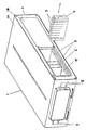
- the single figure shows a high-temperature storage battery 1, with a double-walled housing 2 and storage cells 3, which are combined into modules 4.
- An evacuated space is located between the outer housing wall 2A and the inner housing wall 2B, which is filled with an insulating material (not shown here).
- a cavity 5 is provided in the interior of the housing 2 and is divided into individual sections with the aid of partition walls 6. Each section has at least one supply 7 for air.
- Each module 4 contains a defined number of memory cells 3.
- a module 4 is arranged in a section of the interior 5.
- lines 8 and 9 are provided, via which the cooling air is supplied and removed and the storage cells 3 are electrically connected to the outside. In the high-temperature storage battery shown here, the air is introduced through the openings 7 into the interior 5 thereof.
- the cooling air is directed outside again via further openings (not shown here).
- the memory cells 3 operate at a temperature T A of 350 ° C. This temperature T A should be exceeded only a little below or only a little, so that the memory cells 3 always deliver optimal performance and not, for. B. damaged by overheating. Therefore, the target value T1 of the internal temperature T is also set to 350 ° C.
- its internal temperature T is determined by the heat loss of the electricity generated or the power output, as well as the heat dissipation of the cooling device and the thermal losses of the battery insulation. So that the weight of the high-temperature storage batteries does not become too large, they are equipped with cooling devices that are as small as possible.
- the current or power is first calculated according to the invention, which, taking into account the available cooling power and the thermal losses of the high-temperature storage battery 1, causes an internal temperature T of 350 ° C.
- This current is calculated according to the following equation:
- EG stands for the entrophy element
- Ri for the cell internal resistance (Ohm)
- Pi for the thermal losses through the insulation
- Pv for other thermal losses of the battery
- Pk for the heat dissipation through the cooling device
- Zp for the number of parallel switched memory cells 3.
- the internal temperature T of the high-temperature storage battery is measured continuously at the same time.
- the maximum permissible internal temperature T m of the high-temperature storage battery is 380 ° C. If the internal temperature T approaches a value of 350 ° C., which corresponds to the working temperature T A of the storage cell 3, the cooling device is switched on and cooling air is supplied to the storage cells 3 via the openings 7.
- the temperature T2 at which the cooling is switched on is determined once for each battery type and is 350 ° C. However, it can also be slightly above.
- the output power of the high-temperature storage battery is reduced. Then only such a current is generated, the heat loss causes an internal temperature which corresponds to the desired value of the internal temperature T 1 of 350 ° C. So that this setting to a new current is easily possible, the associated internal temperatures are determined on the basis of the specific parameters of the high-temperature storage battery 1 after the completion of the high-temperature storage battery 1 for several current values.
Landscapes
- Engineering & Computer Science (AREA)
- Manufacturing & Machinery (AREA)
- Chemical & Material Sciences (AREA)
- Chemical Kinetics & Catalysis (AREA)
- Electrochemistry (AREA)
- General Chemical & Material Sciences (AREA)
- Automation & Control Theory (AREA)
- Secondary Cells (AREA)
- Supply Devices, Intensifiers, Converters, And Telemotors (AREA)
- Laying Of Electric Cables Or Lines Outside (AREA)
- Connection Of Batteries Or Terminals (AREA)
Abstract
Description
- Die Erfindung bezieht sich auf ein Verfahren zur Vermeidung der Überhitzung von Hochtemperatur-Speicherbatterien gemäß dem Oberbegriff des Patentanspruches 1.
- Solche Hochtemperatur-Speicherbatterien, die unter Verwendung von wiederaufladbaren elektrochemischen Speicherzellen aufgebaut sind, werden in vermehrtem Maße fur den Elektroantrieb von Fahrzeugen eingesetzt.
- Die bis jetzt bekannt gewordenen Hochtemperatur-Speicherbatterien sind aus einer Vielzahl von elektrochemischen Speicherzellen aufgebaut. Für die Bildung solcher Hochtemperatur-Speicherbatterien die einen Energieinhalt von etwa 40 kWh aufweisen sollen, sind etwa 500 Speicherzellen erforderlich. Diese Speicherzellen beinhalten Natrium und Schwefel als Reaktanden und arbeiten bei einer Temperatur von 350 °C. Um Wärmeverluste zu vermeiden sind die Speicherzellen von einer thermischen Isolierung umgeben. Andererseits muß jedoch auch für eine ausreichende Kühlung der Speicherzellen gesorgt werden, damit die Betriebstemperatur derselben nicht überschritten und eine Beschädigung der Speicherzellen unterbunden wird.
- Bei den bisher bekannten Hochtemperatur-Speicherbatterien erfolgt die Kühlung der Speicherzellen vorzugsweise durch Luft, welche an den Speicherzellen vorbeigeleitet wird, bzw. durch Kühlkanäle hindurchgeleitet wird, die zwischen den Speicherzellen angeordnet sind. Um die Innentemperatur der Hochtemperatur-Speicherbatterien auf der gewünschten Arbeitstemperatur zu halten, und die Ausbildung von Wärmenestern zwischen den Speicherzellen zu vermeiden, sind die bisher verwendeten Kühleinrichtungen wesentlich großer ausgebildet als erforderlich.
- Der Erfindung liegt deshalb die Aufgabe zugrunde, ein Verfahren zur Vermeidung der Überhitzung einer Hochtemperatur-Speicherbatterie aufzuzeigen, mit dem die vorgegebene Innentemperatur auch mit einer Kühleinrichtung beibehalten werden kann, die kleiner dimensioniert ist.
- Diese Aufgabe wird erfindungsgemäß durch die Merkmale des Patentanspruches 1 gelöst.
- Das Verfahren ist so ausgebildet, daß die Kühleinrichtung nur dann betätigt wird, wenn durch die abgegebene Leistung der Soll-Wert der Innentemperatur der Hochtemperatur-Speicherbatterie überschritten wird. Vorzugsweise entspricht dieser Soll-Wert der Innentemperatur der Arbeitstemperatur der Speicherzellen. Durch eine zusätzliche Begrenzung der abzugebenden Leistung beim Erreichen eines definierten Wertes der Innentemperatur kann dieser an einem weiteren Ansteigen gehindert werden. Dies bedeutet gleichzeitig, daß die Begrenzung der Innentemperatur und ihre Rückführung auf den gewünschten Soll-Wert nicht durch die Kühleinrichtung alleine bewirkt werden muß. Hiermit ist es möglich, eine kleiner dimensionierte Kühleinrichtung zu verwenden.
- Weitere erfindungswesentliche Merkmale sind in den Unteransprüchen gekennzeichnet.
- Das erfindungsgemäße Verfahren wird nachfolgend anhand einer Zeichnung erläutert.
- Die einzige Figur zeigt eine Hochtemperatur-Speicherbatterie 1, mit einem doppelwandigen Gehäuse 2 und Speicherzellen 3, die zu Modulen 4 zusammengefaßt sind. Zwischen der äußeren Gehäusewandung 2A und der inneren Gehäusewandung 2B befindet sich ein evakuierter Raum, der mit einem Isoliermaterial (hier nicht dargestellt) ausgefüllt ist. Im Inneren des Gehäuses 2 ist ein Hohlraum 5 vorgesehen, der mit Hilfe von Trennwänden 6 in einzelne Abschnitte unterteilt ist. Jeder Abschnitt weist mindestens eine Zuführung 7 für Luft auf. Jeder Modul 4 enthält eine definierte Anzahl von Speicherzellen 3. Jeweils ein Modul 4 ist in einem Abschnitt des Innenraumes 5 angeordnet. Desweiteren sind Leitungen 8 und 9 vorgesehen, über welche die Zu- und Abfuhr der Kühlluft und der elektrische Anschluß der Speicherzellen 3 nach außenhin erfolgt. Bei der hier dargestellten Hochtemperaturspeicherbatterie wird die Luft durch die Öffnungen 7 in den Innenraum 5 derselben eingeleitet. Über weitere Öffnungen (hier nicht dargestellt) wird die Kühlluft wieder nach außen geleitet. Die Speicherzellen 3 arbeiten bei einer Temperatur TA von 350 °C. Diese Temperatur TA sollte nur wenig unter bzw. nur wenig überschritten werden, so daß die Speicherzellen 3 immer eine optimale Leistung abgeben und nicht, z. B. durch eine Überhitzung beschädigt werden. Deshalb wird der Sollwert T₁ der Innentemperatur T ebenfalls auf 350 °C festgelegt. Beim Betrieb der Hochtemperatur-Speicher batterie 1 wird deren Innentemperatur T durch die Verlustwärme des erzeugten Stromes bzw. die abgegebenen Leistung sowie die Wärmeabfuhr der Kühleinrichtung und die thermischen Verluste der Batterieisolation bestimmt. Damit das Gewicht der Hochtemperatur-Speicherbatterien nicht zu groß wird, werden diese mit Kühleinrichtungen ausgerüstet, die so klein wie möglich ausgebildet sind. Um eine Überhitzung der Hochtemperatur-Speicherbatterien mit dieser klein dimensionierten Kühleinrichtung zu vermeiden, wird erfindungsgemäß zunächst der Strom bzw. die Leistung berechnet, die unter Berücksichtigung der verfügbaren Kühlleistung und der thermischen Verluste der Hochtemperatur-Speicherbatterie 1 eine Innentemperatur T von 350 °C hervorruft. Dieser Strom berechnet sich gemäß der nachfolgenden Gleichung:

- In der obigen Gleichung steht EG stellvertretend für das Entrophieglied, Ri für den Zellinnenwiderstand (Ohm), Pi für die thermischen Verluste durch die Isolation, Pv für sonstige thermische Verluste der Batterie, Pk für die Wärmeabfuhr durch die Kühleinrichtung und Zp für die Anzahl der parallel geschalteten Speicherzellen 3.
- Wird nun an einen Verbraucher (hier nicht dargestellt), der an die Hochtemperaturspeicherbatterie 1 angeschlossen ist, dieser berechnete Strom bzw. die zugehörige Leistung abgegeben, so wird gleichzeitig die Innentemperatur T der Hochtemperatur-Speicherbatterie kontinuierlich gemessen. Bei dem hier dargestellten Ausfüh rungsbeispiel wird davon ausgegangen, daß die maximal zulässige Innentemperatur Tm der Hochtemperatur-Speicherbatterie 380°C beträgt. Nähert sich die Innentemperatur T einem Wert von 350 °C, welcher der Arbeitstemperatur TA der Speicherzelle 3 entspricht, so wird die Kühleinrichtung eingeschaltet, und den Speicherzellen 3 über die Öffnungen 7 Kühlluft zugeführt. Die Temperatur T₂, bei der die Kühlung eingeschaltet wird, wird einmal für jeden Batterietyp ermittelt und liegt bei 350 °C. Sie kann jedoch auch etwas oberhalb liegen. Wird bei den Messungen der Innentemperatur T festgestellt, daß diese über 350 °C ansteigt und sich einer Temperatur T₃ von, Z.B. 360 °C nähert, wird die abgegebene Leistung der Hochtemperatur-Speicherbatterie reduziert. Es wird dann nur ein solcher Strom erzeugt, dessen Verlustwärme eine Innentemperatur hervorruft, die dem angestrebten Wert der Innentemperatur T₁ von 350 °C entspricht. Damit diese Einstellung auf einen neuen Strom einfach möglich ist, werden nach der Fertigstellung der Hochtemperaturspeicherbatterie 1 zu mehreren Stromwerten die zugehörigen Innentemperaturen unter Zugrundelegung der spezifischen Parameter der Hochtemperaturspeicherbatterie 1 ermittelt.
- Diese so eingestellte reduzierte Leistung wird solange beibehalten, bis die Innentemperatur T wieder etwa 92 % ihres Maximalwertes Tm aufweist. Ist dieser Zustand erreicht, so wird die Kühleinrichtung wieder abgeschaltet und die Begrenzung der Leistungsabgabe wieder aufgehoben.
Durch diese Maßnahmen ist es möglich, die Hochtemperatur-Speicherbatterie mit einer Kühleinrichtung zu versehen, die wesentlich kleiner dimensioniert ist als die Einrichtungen bei herkömmlichen Hochtemperaturspeicherbatterien dieser Art. Durch die ständige Kontrolle der Innentemperatur T wird sichergestellt, daß die Arbeitstemperatur TA der Speicherzellen 3 überhaupt nicht, oder nur geringfügig unter bzw. überschritten wird.
Claims (7)
Priority Applications (1)
| Application Number | Priority Date | Filing Date | Title |
|---|---|---|---|
| AT88116296T ATE94691T1 (de) | 1987-10-09 | 1988-10-01 | Verfahren zur vermeidung einer ueberhitzung von hochtemperatur-speicherbatterien. |
Applications Claiming Priority (2)
| Application Number | Priority Date | Filing Date | Title |
|---|---|---|---|
| DE3734221 | 1987-10-09 | ||
| DE19873734221 DE3734221A1 (de) | 1987-10-09 | 1987-10-09 | Verfahren zur vermeidung einer ueberhitzung von hochtemperatur-speicherbatterien |
Publications (3)
| Publication Number | Publication Date |
|---|---|
| EP0310982A2 true EP0310982A2 (de) | 1989-04-12 |
| EP0310982A3 EP0310982A3 (en) | 1990-09-05 |
| EP0310982B1 EP0310982B1 (de) | 1993-09-15 |
Family
ID=6338004
Family Applications (1)
| Application Number | Title | Priority Date | Filing Date |
|---|---|---|---|
| EP19880116296 Revoked EP0310982B1 (de) | 1987-10-09 | 1988-10-01 | Verfahren zur Vermeidung einer Überhitzung von Hochtemperatur-Speicherbatterien |
Country Status (6)
| Country | Link |
|---|---|
| US (1) | US4897322A (de) |
| EP (1) | EP0310982B1 (de) |
| JP (1) | JPH01122575A (de) |
| AT (1) | ATE94691T1 (de) |
| DE (2) | DE3734221A1 (de) |
| ES (1) | ES2046269T3 (de) |
Cited By (1)
| Publication number | Priority date | Publication date | Assignee | Title |
|---|---|---|---|---|
| DE102011007840A1 (de) * | 2011-04-21 | 2012-10-25 | Bayerische Motoren Werke Aktiengesellschaft | Verfahren und Vorrichtung zur Ermittlung der Innentemperatur eines Energiespeichers |
Families Citing this family (15)
| Publication number | Priority date | Publication date | Assignee | Title |
|---|---|---|---|---|
| DE3937158A1 (de) * | 1989-11-08 | 1991-05-16 | Bosch Gmbh Robert | Kontrolleinrichtung fuer batteriegeraet |
| DE4017475A1 (de) * | 1990-05-31 | 1991-12-05 | Standard Elektrik Lorenz Ag | Anordnung mit einem elektrischen akkumulator |
| JPH04358950A (ja) * | 1991-05-31 | 1992-12-11 | Honda Motor Co Ltd | 電動式車両 |
| US5477936A (en) * | 1991-10-19 | 1995-12-26 | Honda Giken Kogyo Kabushiki Kaisha | Electric motor vehicle and battery unit for electric motor vehicle |
| JP3242153B2 (ja) * | 1992-06-08 | 2001-12-25 | 本田技研工業株式会社 | バッテリモジュールの温度調節用構造体 |
| JPH06278667A (ja) * | 1993-01-26 | 1994-10-04 | Honda Motor Co Ltd | 電動車両 |
| JP3412701B2 (ja) * | 1993-10-19 | 2003-06-03 | 本田技研工業株式会社 | 電動車両のカバー構造および電池収納ケース構造 |
| DE4443015A1 (de) * | 1993-12-09 | 1995-06-14 | Aabh Patent Holdings | Verfahren zum Betrieb von Hochtemperaturbatterien |
| JP3451141B2 (ja) * | 1994-11-14 | 2003-09-29 | 本田技研工業株式会社 | バッテリ温度調節装置 |
| JP3451142B2 (ja) * | 1994-11-18 | 2003-09-29 | 本田技研工業株式会社 | 温度制御機構を備えたバッテリ組立体 |
| US5985482A (en) * | 1998-04-28 | 1999-11-16 | Gnb Technologies, Inc. | Snap-on battery heat shield |
| US20050139445A1 (en) * | 2002-12-12 | 2005-06-30 | Bosk Brian K. | Wedge clutch assembly |
| DE10319350B4 (de) * | 2003-04-29 | 2008-12-04 | Akkumulatorenfabrik Moll Gmbh & Co. Kg | Batteriekastenmodul für ein Fahrzeug, insbesondere ein Kraftfahrzeug |
| RU2414778C1 (ru) * | 2009-11-26 | 2011-03-20 | Российская Федерация, От Имени Которой Выступает Министерство Промышленности И Торговли Российской Федерации | Буферный накопитель энергии |
| WO2016136507A1 (ja) * | 2015-02-23 | 2016-09-01 | 日本碍子株式会社 | 蓄電池制御装置 |
Family Cites Families (10)
| Publication number | Priority date | Publication date | Assignee | Title |
|---|---|---|---|---|
| DE6608151U (de) * | 1964-02-25 | 1971-07-01 | Daimler Benz Ag | Vorrichtung zum aufwaermen oder warmhalten von elektrischen batterien, insbesondere fuer kraftfahrzeuge. |
| GB1529854A (en) * | 1975-05-22 | 1978-10-25 | Atomic Energy Authority Uk | Electric cells |
| JPS5258822A (en) * | 1975-11-11 | 1977-05-14 | Kogyo Gijutsuin | Sodiummsulfur battery |
| GB2081000B (en) * | 1980-07-23 | 1984-01-18 | Chloride Silent Power Ltd | Controlling the temperature of eg sodium-sulphur batteries |
| US4376809A (en) * | 1980-11-06 | 1983-03-15 | Chloride Silent Power Limited | Sodium sulphur batteries and cell modules therefor |
| JPS58112273A (ja) * | 1981-12-25 | 1983-07-04 | Yuasa Battery Co Ltd | 蓄電池 |
| EP0096265B1 (de) * | 1982-06-03 | 1986-08-20 | BROWN, BOVERI & CIE Aktiengesellschaft | Elektrochemische Speicherzelle |
| DE3242901A1 (de) * | 1982-11-20 | 1984-05-24 | Brown, Boveri & Cie Ag, 6800 Mannheim | Hochtemperatur-speicherbatterie |
| DE3513079A1 (de) * | 1984-04-17 | 1985-10-17 | Volkswagenwerk Ag, 3180 Wolfsburg | Verfahren und einrichtung zur batterieheizung |
| US4727006A (en) * | 1986-02-12 | 1988-02-23 | The United States Of America As Represented By The Secretary Of The Army | Method of monitoring electrochemical cells |
-
1987
- 1987-10-09 DE DE19873734221 patent/DE3734221A1/de not_active Ceased
-
1988
- 1988-10-01 DE DE88116296T patent/DE3884123D1/de not_active Revoked
- 1988-10-01 ES ES88116296T patent/ES2046269T3/es not_active Expired - Lifetime
- 1988-10-01 EP EP19880116296 patent/EP0310982B1/de not_active Revoked
- 1988-10-01 AT AT88116296T patent/ATE94691T1/de active
- 1988-10-06 JP JP63252851A patent/JPH01122575A/ja active Pending
- 1988-10-11 US US07/882,558 patent/US4897322A/en not_active Expired - Fee Related
Cited By (3)
| Publication number | Priority date | Publication date | Assignee | Title |
|---|---|---|---|---|
| DE102011007840A1 (de) * | 2011-04-21 | 2012-10-25 | Bayerische Motoren Werke Aktiengesellschaft | Verfahren und Vorrichtung zur Ermittlung der Innentemperatur eines Energiespeichers |
| US10062932B2 (en) | 2011-04-21 | 2018-08-28 | Bayerische Motoren Werke Aktiengesellschaft | Method and device for determining the internal temperature of an energy storage device |
| US10873110B2 (en) | 2011-04-21 | 2020-12-22 | Bayerische Motoren Werke Aktiengesellschaft | Device for determining the internal temperature of an energy storage device |
Also Published As
| Publication number | Publication date |
|---|---|
| DE3734221A1 (de) | 1989-04-20 |
| ES2046269T3 (es) | 1994-02-01 |
| EP0310982A3 (en) | 1990-09-05 |
| US4897322A (en) | 1990-01-30 |
| EP0310982B1 (de) | 1993-09-15 |
| ATE94691T1 (de) | 1993-10-15 |
| JPH01122575A (ja) | 1989-05-15 |
| DE3884123D1 (de) | 1993-10-21 |
Similar Documents
| Publication | Publication Date | Title |
|---|---|---|
| EP0310982B1 (de) | Verfahren zur Vermeidung einer Überhitzung von Hochtemperatur-Speicherbatterien | |
| DE10202807B4 (de) | Vorrichtung zur Temperierung von Hochleistungs-Sekundärbatterien für Fahrzeuganwendungen | |
| DE69502207T2 (de) | Bimodales Batteriesystem für Elektrofahrzeuge | |
| DE102006061270B4 (de) | Batteriepack und Batteriemodul | |
| DE69822727T2 (de) | Mehrzellige elektrische sekundär batterie | |
| EP0933829B1 (de) | Verfahren zur Verbesserung der Lade- und Entladefähigkeit von Akkumulatoren | |
| DE112008001424T5 (de) | Elektrische Speichervorrichtung und Fahrzeug | |
| WO2012019740A1 (de) | Umhüllung für eine elektrochemische zelle | |
| DE102014215550A1 (de) | Elektrisches Energiespeichermodul und entsprechender modular aufgebauter Energiespeicher | |
| DE102010063057A1 (de) | Batteriesystem für ein Kraftfahrzeug mit wenigstens einer elektrochemischen Zelle und wenigstens einem Latentwärmespeicher | |
| DE102018100691A1 (de) | Hochleistungsakkumodul oder Hochleistungskondensatormodul | |
| DE102013012164A1 (de) | Traktions-Batteriesystem und Verfahren zum Erwärmen einer Hochvolt-Batterie eines Traktions-Batteriesystems | |
| WO2020007561A1 (de) | Batteriezelle mit heizeinrichtung, hochvoltbatterie sowie kraftfahrzeug | |
| DE102020109872B3 (de) | Elektrischer Energiespeicher für ein Kraftfahrzeug sowie Verfahren zum Betreiben eines solchen elektrischen Energiespeichers | |
| DE102020007267A1 (de) | Lithiumionenbatterievorrichtung für ein Fahrzeug | |
| DE102009035466A1 (de) | Formierung von Einzelzellen | |
| EP2457276A1 (de) | Elektrochemischer energiespeicher und verfahren zum kühlen oder erwärmen eines elektrochemischen energiespeichers | |
| WO2013107491A1 (de) | Zellengehäuse für elektrochemische zellen zum aufbau eines elektrochemischen energiespeichers | |
| WO2015052006A1 (de) | Batteriezelle und herstellungsverfahren für diese, sowie batterie | |
| DE112019006047T5 (de) | Integrierte batterieeinheit | |
| DE202018100173U1 (de) | Hochleistungsakkumodul oder Hochleistungskondensatormodul | |
| EP2889930B1 (de) | Traktionsbatterie mit bremswiderstandsaufladegerät | |
| DE102013114541A1 (de) | Traktionsbatterie mit Modulen | |
| DE9105260U1 (de) | Batteriesatz für den Antrieb eines Fahrzeugs | |
| WO2009089823A1 (de) | Energiespeicher und bordnetz mit einem solchen energiespeicher |
Legal Events
| Date | Code | Title | Description |
|---|---|---|---|
| PUAI | Public reference made under article 153(3) epc to a published international application that has entered the european phase |
Free format text: ORIGINAL CODE: 0009012 |
|
| AK | Designated contracting states |
Kind code of ref document: A2 Designated state(s): AT BE DE ES FR GB IT NL SE |
|
| PUAL | Search report despatched |
Free format text: ORIGINAL CODE: 0009013 |
|
| AK | Designated contracting states |
Kind code of ref document: A3 Designated state(s): AT BE DE ES FR GB IT NL SE |
|
| 17P | Request for examination filed |
Effective date: 19901015 |
|
| 17Q | First examination report despatched |
Effective date: 19920722 |
|
| GRAA | (expected) grant |
Free format text: ORIGINAL CODE: 0009210 |
|
| AK | Designated contracting states |
Kind code of ref document: B1 Designated state(s): AT BE DE ES FR GB IT NL SE |
|
| REF | Corresponds to: |
Ref document number: 94691 Country of ref document: AT Date of ref document: 19931015 Kind code of ref document: T |
|
| PGFP | Annual fee paid to national office [announced via postgrant information from national office to epo] |
Ref country code: SE Payment date: 19930929 Year of fee payment: 6 |
|
| ITF | It: translation for a ep patent filed | ||
| ET | Fr: translation filed | ||
| PGFP | Annual fee paid to national office [announced via postgrant information from national office to epo] |
Ref country code: ES Payment date: 19931021 Year of fee payment: 6 |
|
| REF | Corresponds to: |
Ref document number: 3884123 Country of ref document: DE Date of ref document: 19931021 |
|
| PGFP | Annual fee paid to national office [announced via postgrant information from national office to epo] |
Ref country code: BE Payment date: 19931022 Year of fee payment: 6 |
|
| GBT | Gb: translation of ep patent filed (gb section 77(6)(a)/1977) |
Effective date: 19930927 |
|
| PGFP | Annual fee paid to national office [announced via postgrant information from national office to epo] |
Ref country code: NL Payment date: 19931031 Year of fee payment: 6 |
|
| REG | Reference to a national code |
Ref country code: ES Ref legal event code: FG2A Ref document number: 2046269 Country of ref document: ES Kind code of ref document: T3 |
|
| PLBI | Opposition filed |
Free format text: ORIGINAL CODE: 0009260 |
|
| 26 | Opposition filed |
Opponent name: AEG AKTIENGESELLSCHAFT Effective date: 19940607 |
|
| PG25 | Lapsed in a contracting state [announced via postgrant information from national office to epo] |
Ref country code: SE Effective date: 19941002 |
|
| NLR1 | Nl: opposition has been filed with the epo |
Opponent name: AEG AG. |
|
| PG25 | Lapsed in a contracting state [announced via postgrant information from national office to epo] |
Ref country code: ES Free format text: LAPSE BECAUSE OF NON-PAYMENT OF DUE FEES Effective date: 19941003 |
|
| PG25 | Lapsed in a contracting state [announced via postgrant information from national office to epo] |
Ref country code: BE Effective date: 19941031 |
|
| EAL | Se: european patent in force in sweden |
Ref document number: 88116296.0 |
|
| BERE | Be: lapsed |
Owner name: ASEA BROWN BOVERI A.G. Effective date: 19941031 |
|
| PG25 | Lapsed in a contracting state [announced via postgrant information from national office to epo] |
Ref country code: NL Effective date: 19950501 |
|
| PLAB | Opposition data, opponent's data or that of the opponent's representative modified |
Free format text: ORIGINAL CODE: 0009299OPPO |
|
| NLV4 | Nl: lapsed or anulled due to non-payment of the annual fee | ||
| R26 | Opposition filed (corrected) |
Opponent name: AEG AKTIENGESELLSCHAFT Effective date: 19940607 |
|
| EUG | Se: european patent has lapsed |
Ref document number: 88116296.0 |
|
| PGFP | Annual fee paid to national office [announced via postgrant information from national office to epo] |
Ref country code: GB Payment date: 19960812 Year of fee payment: 9 Ref country code: AT Payment date: 19960812 Year of fee payment: 9 |
|
| PGFP | Annual fee paid to national office [announced via postgrant information from national office to epo] |
Ref country code: FR Payment date: 19960813 Year of fee payment: 9 |
|
| PGFP | Annual fee paid to national office [announced via postgrant information from national office to epo] |
Ref country code: DE Payment date: 19961014 Year of fee payment: 9 |
|
| RDAH | Patent revoked |
Free format text: ORIGINAL CODE: EPIDOS REVO |
|
| RDAG | Patent revoked |
Free format text: ORIGINAL CODE: 0009271 |
|
| STAA | Information on the status of an ep patent application or granted ep patent |
Free format text: STATUS: PATENT REVOKED |
|
| GBPR | Gb: patent revoked under art. 102 of the ep convention designating the uk as contracting state |
Free format text: 961115 |
|
| 27W | Patent revoked |
Effective date: 19961115 |