EP0310213A2 - Self draining container - Google Patents
Self draining container Download PDFInfo
- Publication number
- EP0310213A2 EP0310213A2 EP88301847A EP88301847A EP0310213A2 EP 0310213 A2 EP0310213 A2 EP 0310213A2 EP 88301847 A EP88301847 A EP 88301847A EP 88301847 A EP88301847 A EP 88301847A EP 0310213 A2 EP0310213 A2 EP 0310213A2
- Authority
- EP
- European Patent Office
- Prior art keywords
- pouring spout
- container body
- container
- spout
- ring member
- Prior art date
- Legal status (The legal status is an assumption and is not a legal conclusion. Google has not performed a legal analysis and makes no representation as to the accuracy of the status listed.)
- Granted
Links
Images


Classifications
-
- B—PERFORMING OPERATIONS; TRANSPORTING
- B65—CONVEYING; PACKING; STORING; HANDLING THIN OR FILAMENTARY MATERIAL
- B65D—CONTAINERS FOR STORAGE OR TRANSPORT OF ARTICLES OR MATERIALS, e.g. BAGS, BARRELS, BOTTLES, BOXES, CANS, CARTONS, CRATES, DRUMS, JARS, TANKS, HOPPERS, FORWARDING CONTAINERS; ACCESSORIES, CLOSURES, OR FITTINGS THEREFOR; PACKAGING ELEMENTS; PACKAGES
- B65D23/00—Details of bottles or jars not otherwise provided for
- B65D23/06—Integral drip catchers or drip-preventing means
-
- B—PERFORMING OPERATIONS; TRANSPORTING
- B29—WORKING OF PLASTICS; WORKING OF SUBSTANCES IN A PLASTIC STATE IN GENERAL
- B29C—SHAPING OR JOINING OF PLASTICS; SHAPING OF MATERIAL IN A PLASTIC STATE, NOT OTHERWISE PROVIDED FOR; AFTER-TREATMENT OF THE SHAPED PRODUCTS, e.g. REPAIRING
- B29C49/00—Blow-moulding, i.e. blowing a preform or parison to a desired shape within a mould; Apparatus therefor
-
- B—PERFORMING OPERATIONS; TRANSPORTING
- B29—WORKING OF PLASTICS; WORKING OF SUBSTANCES IN A PLASTIC STATE IN GENERAL
- B29C—SHAPING OR JOINING OF PLASTICS; SHAPING OF MATERIAL IN A PLASTIC STATE, NOT OTHERWISE PROVIDED FOR; AFTER-TREATMENT OF THE SHAPED PRODUCTS, e.g. REPAIRING
- B29C65/00—Joining or sealing of preformed parts, e.g. welding of plastics materials; Apparatus therefor
- B29C65/02—Joining or sealing of preformed parts, e.g. welding of plastics materials; Apparatus therefor by heating, with or without pressure
- B29C65/06—Joining or sealing of preformed parts, e.g. welding of plastics materials; Apparatus therefor by heating, with or without pressure using friction, e.g. spin welding
- B29C65/0672—Spin welding
Abstract
Description
- Self draining containers are known in the art. These containers include means for returning contents which have dripped or run down the exterior of the pouring spout to the main body of the container.
- Examples of prior art self draining closures are shown in United States Patent No.4,550,862 and United States Patent No. 4,640,855.
- Self draining containers, known in the prior art, often have drawbacks. One of the drawbacks is that it is sometimes difficult to completely remove the contents of the container. Often in prior art self draining containers a portion of the contents is trapped when the container is inverted.
- Many prior art self draining container assemblies are also quite expensive to produce and assemble. Some of thes prior art containers include several components which must be correctly orientated during assembly.
- The self draining container, according to the present invention, includes only three parts. The pouring spout is integrally blow molded along with the container body.
- The present container provides a smooth and generally funnel shaped section between the integral container body and pouring spout wherein essentially the entire contents of the container may be removed through the pouring spout when the container is inverted.
- Because the method of making a self draining container, according to the present invention, include the blow molding of the pouring spout along with the blow molding of the container body, the pouring spout is correctly orientated with respect to the body thereby eliminating an expensive manufacturing step sometimes found in prior art self draining container assemblies.
- A separable ring member surrounds the pouring spout and is attached adjacent the upper end of the container body. The ring member together with the pouring spout define a flow back chamber. An opening forms a path of communication between the flow back chamber and the container body. A cap is mounted over the pouring spout.
-
- Fig. 1 of is a perspective view of a fully assembled self draining container, according to the present invention with a portion of the cap broken away;
- Fig. 2 is a bottom view of the self draining container shown in Fig. 1;
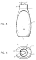
- Fig. 3 is a side elevational view of the self draining container shown in Fig. 1 and having the cap removed;
- Fig. 4 is a top view of the self draining container as shown in Fig. 3;
- Fig. 5 is a fragmentary exploded view showing the separable ring member in position above the pouring spout; and
- Fig. 6 is a fragmentary sectional view showing the ring member after it has been attached to the pouring spout.
- A self draining container, according to the present invention is generally indicated by
reference number 10. While theself draining container 10, depicted in these drawings, is a plastic bottle specifically designed for liquids, other self draining containers which fall within the scope of the present invention may be constructed of other materials and used to contain liquids, powders or granules. - The
self draining container 10 includes a generally cup shaped container body 11 havingsidewalls 12 and abottom 13. In the present embodiment, the container body 11 is blow molded from a high density polyethylene. Referring to Figs. 3, 5 and 6, an integral blow moldedpouring spout 14 is located adjacent theupper end 15 of the container body 11. The upper end of thebody 15 and thepouring spout 14 define a generally funnel shapedsection 16. As viewed in Fig. 6, the funnelshaped section 16 has a reducing diameter as it moves upwardly from theupper end 15 of the body 11 terminating in the angularupper end 17 of thepouring spout 14. Thepouring spout 14 has a reduced diameter at its upper end. - Referring to Figs. 5 and 6, in the present embodiment, a
separable ring member 20 is attached to thepouring spout 14. Thering member 20 is an injection molded ring member also constructed of high density polyethylene. The interior of theseparable ring member 20 includes acircular layer 21 andinternal threads 22. Referring to Fig. 5, the blow molded pouringspout 14 includes a plurality ofannular ridges 23 which mate with thecircular layer 21 and the interior of thering member 20. As shown in Fig. 6, thering member 20 is attached by spin-welding to thepouring spout 14. However, thering member 20 may be attached to thepouring spout 14 by other methods including threading, adhesion and sonic welding. - The
ring member 20 and thepouring spout 14 define a flow back chamber 24. The chamber 24 receives container contents which, for example, spill along the exterior of thepouring spout 14. Adrain back opening 25 is defined by thepouring spout 14 and provides a path of communication between the flow back chamber 24 and the interior of the container body 11. Acap 26 having alower skirt 27, which definesmating threads 28, is positioned over thepouring spout 14. Themating threads 28 engaging thering member threads 22. It is understood that many styles of caps and threading devices may be utilized and still fall within the scope of the present invention. - It has been found in use that because of the funnel
shaped section 16 defined by theupper end 15 of the container body 11 and theintegral pouring spout 14 that when thecontainer 10 is inverted almost the entire contents of the container may be removed. - Furthermore, because the container body 11 and the
pouring spout 14 are integrally blow molded, there only remains theseparable ring member 20 to attach. Because the ring member is circular, the spout orientation problem found in many prior art self draining container assemblies does not occur. - When making a
self draining container 10, according to the present invention, the container body 11 and itsintegral pouring spout 14 are blow molded. The body 11 and thespout 14 define the generally funnelshaped section 16. Next, thepouring spout 14 is cut to form the slanted opening or angularupper end 17. Either before or after the cutting of thepouring spout end 14, the drain back opening 25 is cut in thepouring spout 14 or in the upper end of thebody 15 to define a path from the flow back chamber 24 into the container body 11. - Next, the separable
plastic ring 20 is attached in surrounding relationship to thepouring spout 14 adjacent theupper end 15 of the container body 11. - Lastly, the
cap 26 is mounted over thepouring spout 14. - Many revisions and changes may be made to the various elements of the preferred embodiment of the self draining container described above without departing from the scope of the following claims.
Claims (7)
blow molding a container body having a blow molded pouring spout at its upper end, said body and said spout defining a generally funnel shaped section,
cutting the spout to form an angular upper end,
cutting an opening in said spout defining a path into the container body,
attaching a separable plastic ring member to the spout adjacent the upper end of the container body, wherein the ring member and said spout define a flow back chamber in communication with the opening,
and mounting a plastic cap over the pouring spout.
Applications Claiming Priority (2)
| Application Number | Priority Date | Filing Date | Title |
|---|---|---|---|
| US07/103,334 US4890768A (en) | 1987-10-01 | 1987-10-01 | Self draining container |
| US103334 | 1998-06-23 |
Publications (3)
| Publication Number | Publication Date |
|---|---|
| EP0310213A2 true EP0310213A2 (en) | 1989-04-05 |
| EP0310213A3 EP0310213A3 (en) | 1990-01-31 |
| EP0310213B1 EP0310213B1 (en) | 1995-05-17 |
Family
ID=22294625
Family Applications (1)
| Application Number | Title | Priority Date | Filing Date |
|---|---|---|---|
| EP88301847A Expired - Lifetime EP0310213B1 (en) | 1987-10-01 | 1988-03-03 | Self draining container |
Country Status (8)
| Country | Link |
|---|---|
| US (1) | US4890768A (en) |
| EP (1) | EP0310213B1 (en) |
| JP (1) | JPH0199985A (en) |
| AU (1) | AU580482B1 (en) |
| CA (1) | CA1309383C (en) |
| DE (1) | DE3853803T2 (en) |
| MX (1) | MX166989B (en) |
| ZA (1) | ZA881649B (en) |
Families Citing this family (18)
| Publication number | Priority date | Publication date | Assignee | Title |
|---|---|---|---|---|
| US4981239A (en) * | 1989-01-03 | 1991-01-01 | The Procter & Gamble Company | Container having a drain-back spout |
| US5071037A (en) * | 1989-09-14 | 1991-12-10 | Graham Engineering Corporation | Blow molded bottle with integral pour spout |
| GB8922478D0 (en) * | 1989-10-05 | 1989-11-22 | Procter & Gamble | Flowable product package incorporating a refill facilitating pouring spout |
| US5431306A (en) * | 1993-12-31 | 1995-07-11 | Innovative Molding, Inc. | Drain back container with internal thread |
| US5649650A (en) * | 1994-05-16 | 1997-07-22 | Owens-Illinois Plastic Products Inc. | Liquid containing package with snap fit non-rotating spout insert |
| US5850953A (en) * | 1997-01-28 | 1998-12-22 | Aptargroup, Inc. | Drip-free dispensing structure with collecting reservoir |
| US5941422A (en) * | 1998-04-06 | 1999-08-24 | Owens-Brockway Plastic Products Inc. | Liquid containing and dispensing package |
| US6085949A (en) * | 1998-05-05 | 2000-07-11 | Liquid Container L.P. | Container with molded-in directional pour guide |
| WO2000040475A1 (en) | 1998-12-30 | 2000-07-13 | Unilever Plc | Manufactured pour spout fitment and container |
| US6648188B2 (en) | 1999-12-21 | 2003-11-18 | Owens-Brockway Plastic Products Inc. | Liquid dispensing package and method of manufacture |
| USD482973S1 (en) | 2001-08-14 | 2003-12-02 | Nsi Innovation Llc | Square paint container |
| USD472145S1 (en) | 2001-08-14 | 2003-03-25 | Nottingham-Spirk Partners, Llc | Paint container lid |
| USD480973S1 (en) | 2001-08-14 | 2003-10-21 | Nsi Innovation Llp | Design for a round paint container |
| USD473790S1 (en) | 2001-08-14 | 2003-04-29 | Nottingham-Spirk Partners, Llc | Paint container insert |
| US6968980B2 (en) * | 2003-12-30 | 2005-11-29 | Unilever Home & Personal Care Usa, A Division Of Conopco, Inc. | Pour spout fitment and container |
| US20070210123A1 (en) * | 2006-03-07 | 2007-09-13 | Penny Michael E | Container having blown pour spout |
| US9827729B2 (en) | 2012-05-25 | 2017-11-28 | Phoenix Packaging Operations, LLC | Food container top with integrally formed utensil |
| CH715333A1 (en) * | 2018-09-14 | 2020-03-31 | Alpla Werke Alwin Lehner Gmbh & Co Kg | Plastic container with a pouring element and a closure. |
Citations (3)
| Publication number | Priority date | Publication date | Assignee | Title |
|---|---|---|---|---|
| FR1085312A (en) * | 1953-10-20 | 1955-01-31 | Gutter intended to stop a liquid flowing along a wall and in particular the drops of a liquid flowing along a container | |
| US4640855A (en) * | 1985-10-25 | 1987-02-03 | Owens-Illinois, Inc. | Plastic container with integral spout |
| US4671421A (en) * | 1986-03-06 | 1987-06-09 | Owens-Illinois, Inc. | Plastic container |
Family Cites Families (8)
| Publication number | Priority date | Publication date | Assignee | Title |
|---|---|---|---|---|
| US2601039A (en) * | 1949-12-01 | 1952-06-17 | Livingstone Jay Gould | Pouring spout |
| US2793790A (en) * | 1956-03-09 | 1957-05-28 | Maurice C Kahler | Dripless pitcher |
| US4082827A (en) * | 1976-02-09 | 1978-04-04 | Chlystun Walter K | Process for blow molding of a spout container |
| US4336891A (en) * | 1980-06-09 | 1982-06-29 | Smithy, Inc. | Adapter closure |
| JPS58141988A (en) * | 1982-02-18 | 1983-08-23 | Hitachi Zosen Corp | Mooring buoy vessel |
| US4550862A (en) * | 1982-11-17 | 1985-11-05 | The Procter & Gamble Company | Liquid product pouring and measuring package with self draining feature |
| GB2137971A (en) * | 1983-02-16 | 1984-10-17 | Hunter Thomas Ltd | Closing Containers |
| US4566509A (en) * | 1984-07-09 | 1986-01-28 | Continental Plastic Containers, Inc. | Closure unit including measuring cup |
-
1987
- 1987-10-01 US US07/103,334 patent/US4890768A/en not_active Expired - Lifetime
-
1988
- 1988-03-02 CA CA000560277A patent/CA1309383C/en not_active Expired - Lifetime
- 1988-03-03 EP EP88301847A patent/EP0310213B1/en not_active Expired - Lifetime
- 1988-03-03 DE DE3853803T patent/DE3853803T2/en not_active Expired - Fee Related
- 1988-03-04 JP JP63049927A patent/JPH0199985A/en active Pending
- 1988-03-07 AU AU12749/88A patent/AU580482B1/en not_active Ceased
- 1988-03-08 ZA ZA881649A patent/ZA881649B/en unknown
- 1988-04-05 MX MX010992A patent/MX166989B/en unknown
Patent Citations (3)
| Publication number | Priority date | Publication date | Assignee | Title |
|---|---|---|---|---|
| FR1085312A (en) * | 1953-10-20 | 1955-01-31 | Gutter intended to stop a liquid flowing along a wall and in particular the drops of a liquid flowing along a container | |
| US4640855A (en) * | 1985-10-25 | 1987-02-03 | Owens-Illinois, Inc. | Plastic container with integral spout |
| US4671421A (en) * | 1986-03-06 | 1987-06-09 | Owens-Illinois, Inc. | Plastic container |
Also Published As
| Publication number | Publication date |
|---|---|
| CA1309383C (en) | 1992-10-27 |
| EP0310213A3 (en) | 1990-01-31 |
| MX166989B (en) | 1993-02-19 |
| AU580482B1 (en) | 1989-01-12 |
| JPH0199985A (en) | 1989-04-18 |
| DE3853803T2 (en) | 1995-09-14 |
| US4890768A (en) | 1990-01-02 |
| ZA881649B (en) | 1988-08-31 |
| DE3853803D1 (en) | 1995-06-22 |
| EP0310213B1 (en) | 1995-05-17 |
Similar Documents
| Publication | Publication Date | Title |
|---|---|---|
| EP0310213A2 (en) | Self draining container | |
| EP0193250B1 (en) | Set up piece for mounting on a can, containing a beverage | |
| US6050435A (en) | Closure with integral self-sealing silicone valve and method for making same | |
| US7175041B2 (en) | Cap with attached utensil | |
| CA2369546C (en) | Self-closing fluid dispensing closure | |
| EP0377475B1 (en) | Container having improved drain means | |
| US4613050A (en) | Baby feed bottles | |
| EP0698560B1 (en) | Liquid containing and dispensing package | |
| CA1109029A (en) | Irrigation cap | |
| JP2529705B2 (en) | Barrel with stopper | |
| EP0112103A2 (en) | Screw-type all plastic closure | |
| US4711360A (en) | Splash-proof closure | |
| CA2220626A1 (en) | Dispensing closure and method of making | |
| JPH0858815A (en) | Torque-resistant closure for sealing container | |
| US4463862A (en) | Thermoplastic container | |
| EP1841661A1 (en) | Dispensing closure, package and method of manufacture | |
| US5388731A (en) | Cap and dispensing fitment combination wherein the cap has retaining means engaging the fitment | |
| EP0275623A1 (en) | Lined closure made by the unscrewing process | |
| EP0187820B1 (en) | Sealed container with replaceable plug insert | |
| EP1077181B1 (en) | Pouring spout for mounting on a container | |
| AU725401B2 (en) | Hermetically sealed container with closure insert | |
| US20040112919A1 (en) | Closure with integrated ventilation | |
| EP0620795B1 (en) | Combination of a closure cap and a bottle | |
| JPH0211314Y2 (en) | ||
| EP0261965A2 (en) | Cap for a container closure |
Legal Events
| Date | Code | Title | Description |
|---|---|---|---|
| PUAI | Public reference made under article 153(3) epc to a published international application that has entered the european phase |
Free format text: ORIGINAL CODE: 0009012 |
|
| AK | Designated contracting states |
Kind code of ref document: A2 Designated state(s): BE DE FR GB IT NL |
|
| PUAL | Search report despatched |
Free format text: ORIGINAL CODE: 0009013 |
|
| AK | Designated contracting states |
Kind code of ref document: A3 Designated state(s): BE DE FR GB IT NL |
|
| 17P | Request for examination filed |
Effective date: 19900403 |
|
| 17Q | First examination report despatched |
Effective date: 19911227 |
|
| GRAA | (expected) grant |
Free format text: ORIGINAL CODE: 0009210 |
|
| ITF | It: translation for a ep patent filed |
Owner name: BARZANO' E ZANARDO ROMA S.P.A. |
|
| AK | Designated contracting states |
Kind code of ref document: B1 Designated state(s): BE DE FR GB IT NL |
|
| ET | Fr: translation filed | ||
| REF | Corresponds to: |
Ref document number: 3853803 Country of ref document: DE Date of ref document: 19950622 |
|
| PLBE | No opposition filed within time limit |
Free format text: ORIGINAL CODE: 0009261 |
|
| STAA | Information on the status of an ep patent application or granted ep patent |
Free format text: STATUS: NO OPPOSITION FILED WITHIN TIME LIMIT |
|
| 26N | No opposition filed | ||
| REG | Reference to a national code |
Ref country code: GB Ref legal event code: IF02 |
|
| PGFP | Annual fee paid to national office [announced via postgrant information from national office to epo] |
Ref country code: FR Payment date: 20050105 Year of fee payment: 18 |
|
| PGFP | Annual fee paid to national office [announced via postgrant information from national office to epo] |
Ref country code: NL Payment date: 20050110 Year of fee payment: 18 Ref country code: GB Payment date: 20050110 Year of fee payment: 18 |
|
| PGFP | Annual fee paid to national office [announced via postgrant information from national office to epo] |
Ref country code: BE Payment date: 20050127 Year of fee payment: 18 |
|
| PGFP | Annual fee paid to national office [announced via postgrant information from national office to epo] |
Ref country code: DE Payment date: 20050228 Year of fee payment: 18 |
|
| PG25 | Lapsed in a contracting state [announced via postgrant information from national office to epo] |
Ref country code: GB Free format text: LAPSE BECAUSE OF NON-PAYMENT OF DUE FEES Effective date: 20060303 |
|
| PG25 | Lapsed in a contracting state [announced via postgrant information from national office to epo] |
Ref country code: BE Free format text: LAPSE BECAUSE OF NON-PAYMENT OF DUE FEES Effective date: 20060331 |
|
| PGFP | Annual fee paid to national office [announced via postgrant information from national office to epo] |
Ref country code: IT Payment date: 20060331 Year of fee payment: 19 |
|
| PG25 | Lapsed in a contracting state [announced via postgrant information from national office to epo] |
Ref country code: NL Free format text: LAPSE BECAUSE OF NON-PAYMENT OF DUE FEES Effective date: 20061001 |
|
| PG25 | Lapsed in a contracting state [announced via postgrant information from national office to epo] |
Ref country code: DE Free format text: LAPSE BECAUSE OF NON-PAYMENT OF DUE FEES Effective date: 20061003 |
|
| GBPC | Gb: european patent ceased through non-payment of renewal fee |
Effective date: 20060303 |
|
| NLV4 | Nl: lapsed or anulled due to non-payment of the annual fee |
Effective date: 20061001 |
|
| REG | Reference to a national code |
Ref country code: FR Ref legal event code: ST Effective date: 20061130 |
|
| BERE | Be: lapsed |
Owner name: *OWENS-ILLINOIS PLASTIC PRODUCTS INC. Effective date: 20060331 |
|
| PG25 | Lapsed in a contracting state [announced via postgrant information from national office to epo] |
Ref country code: FR Free format text: LAPSE BECAUSE OF NON-PAYMENT OF DUE FEES Effective date: 20060331 |
|
| PG25 | Lapsed in a contracting state [announced via postgrant information from national office to epo] |
Ref country code: IT Free format text: LAPSE BECAUSE OF NON-PAYMENT OF DUE FEES Effective date: 20070303 |