EP0310119A2 - Method for positioning a magnetic head and magnetic disk driving apparatus for implementing the method - Google Patents
Method for positioning a magnetic head and magnetic disk driving apparatus for implementing the method Download PDFInfo
- Publication number
- EP0310119A2 EP0310119A2 EP88116212A EP88116212A EP0310119A2 EP 0310119 A2 EP0310119 A2 EP 0310119A2 EP 88116212 A EP88116212 A EP 88116212A EP 88116212 A EP88116212 A EP 88116212A EP 0310119 A2 EP0310119 A2 EP 0310119A2
- Authority
- EP
- European Patent Office
- Prior art keywords
- peak values
- detecting
- detected
- control signal
- calculating
- Prior art date
- Legal status (The legal status is an assumption and is not a legal conclusion. Google has not performed a legal analysis and makes no representation as to the accuracy of the status listed.)
- Granted
Links
Images


Classifications
-
- G—PHYSICS
- G11—INFORMATION STORAGE
- G11B—INFORMATION STORAGE BASED ON RELATIVE MOVEMENT BETWEEN RECORD CARRIER AND TRANSDUCER
- G11B19/00—Driving, starting, stopping record carriers not specifically of filamentary or web form, or of supports therefor; Control thereof; Control of operating function ; Driving both disc and head
- G11B19/02—Control of operating function, e.g. switching from recording to reproducing
- G11B19/10—Control of operating function, e.g. switching from recording to reproducing by sensing presence or absence of record in accessible stored position or on turntable
-
- G—PHYSICS
- G11—INFORMATION STORAGE
- G11B—INFORMATION STORAGE BASED ON RELATIVE MOVEMENT BETWEEN RECORD CARRIER AND TRANSDUCER
- G11B5/00—Recording by magnetisation or demagnetisation of a record carrier; Reproducing by magnetic means; Record carriers therefor
- G11B5/48—Disposition or mounting of heads or head supports relative to record carriers ; arrangements of heads, e.g. for scanning the record carrier to increase the relative speed
- G11B5/58—Disposition or mounting of heads or head supports relative to record carriers ; arrangements of heads, e.g. for scanning the record carrier to increase the relative speed with provision for moving the head for the purpose of maintaining alignment of the head relative to the record carrier during transducing operation, e.g. to compensate for surface irregularities of the latter or for track following
- G11B5/596—Disposition or mounting of heads or head supports relative to record carriers ; arrangements of heads, e.g. for scanning the record carrier to increase the relative speed with provision for moving the head for the purpose of maintaining alignment of the head relative to the record carrier during transducing operation, e.g. to compensate for surface irregularities of the latter or for track following for track following on disks
- G11B5/59605—Circuits
- G11B5/59611—Detection or processing of peak/envelop signals
-
- G—PHYSICS
- G11—INFORMATION STORAGE
- G11B—INFORMATION STORAGE BASED ON RELATIVE MOVEMENT BETWEEN RECORD CARRIER AND TRANSDUCER
- G11B5/00—Recording by magnetisation or demagnetisation of a record carrier; Reproducing by magnetic means; Record carriers therefor
- G11B5/48—Disposition or mounting of heads or head supports relative to record carriers ; arrangements of heads, e.g. for scanning the record carrier to increase the relative speed
- G11B5/54—Disposition or mounting of heads or head supports relative to record carriers ; arrangements of heads, e.g. for scanning the record carrier to increase the relative speed with provision for moving the head into or out of its operative position or across tracks
- G11B5/55—Track change, selection or acquisition by displacement of the head
- G11B5/5521—Track change, selection or acquisition by displacement of the head across disk tracks
- G11B5/5526—Control therefor; circuits, track configurations or relative disposition of servo-information transducers and servo-information tracks for control thereof
- G11B5/553—Details
- G11B5/5547—"Seek" control and circuits therefor
Definitions
- the present invention relates to a method for accurately positioning a magnetic head on a destination track of a magnetic disk and a magnetic disk driving apparatus for implementing the method.
- the magnetic disk has been used on which, for example, a servo pattern is recorded.
- the servo pattern is comprised of, for example, two patterns, each of which exists at one side with respect to a track center. Two signals are read from the two patterns.
- the signals read from the two patterns are such that the signal corresponding to one of the patterns has a peak value larger than the signal corresponding to the other pattern.
- the signals corresponding to the patterns have an equal peak value.
- the magnetic head can be positioned right over the center of a desired track.
- a known method for improving the positional accuracy of the magnetic head is one in which peak values obtained for each of the patterns are averaged for subsequent comparison. This method permits accurate measurement of the amount of positional deviation of the magnetic head from a given track center. On the other hand, if error signals arise due to the disturbance and disk deficiencies at the servo pattern portions, the signals read from the patterns and hence the average values could have abnormal values. This would move the magnetic head to an erroneous position.
- the magnetic disk driving apparatus comprises a driving section for driving the magnetic head on the destination track, in accordance with an input drive instruction, a detecting section for detecting peak values of signal components corresponding to servo data read out from the magnetic disk by the magnetic head, and a controller for generating a drive instruction on the basis of a plurality of peak values selected from among the peak values detected, and outputting the drive instruction to the driving section.
- the positioning method of the present invention comprises the steps of the reading out, by the magnetic head, of servo data from the magnetic disk, in order to detect peak values of signal components corresponding to the servo data, generating a drive instruction on the basis of a plurality of peak values selected from among the peak values detected, and driving the magnetic head on the destination track, in accordance with the drive instruction.
- the magnetic disk driving apparatus of the present invention since abnormal values due to the deficiencies of the servo pattern surface of a recording disk and the disturbance are removed for subsequent average processing, the accurate positioning of the head is always possible.
- a magnetic disk 10 is rotated by spindle motor 8. As shown in Fig. 3A a servo pattern comprising two pattern, each of which exists at one side with respect to track center TC, is recorded on disk 10.
- the disk is assumed to be a floppy disk, on whose servo data surface the servo pattern is embedded, of a so-called sector servo system.
- Magnetic disk 10 may be of servo-surface-servo type or may be a hard disk. In the servo-surface-servo type of magnetic disk, the servo data is read out from a recording surface different from a data recording surface or another magnetic disk by a special head which is drived by an actuator along with the magnetic read/write head.
- Magnetic heads 12 and 42 are supported by a carriage mechanism 34 to be positioned on destination tracks in accordance with a drive instruction from CPU 30.
- Signals corresponding to servo data 61-63 and 71-73 read from magnetic disk 10 by magnetic head 12, for example, are amplified in amplifier 14 and then applied to timing extractor 16.
- Timing extractor 16 generates various control signals from the amplified signals.
- Switch 15 is responsive to a switching control signal from timing extractor 16 to feed the amplified signals corresponding to servo data 61-63 in pattern A to a peak hold circuit (P/H) 18 and to feed amplified signals corresponding to servo data 71-73 in pattern B to a peak hold circuit (P/H) 20.
- Peak hold circuits 18 and 20 hold peak values of the amplified signals in response to hold control signals from timing extractor 16, respectively.
- peak hold circuits 18 and 20 are converted to digital data by analog-to-digital (A/D) converters 22 and 24 in accordance with conversion control signals from timing extractor 16, respectively, and then stored into fast-in fast-out (FIFO) memories 26 and 28 in accordance with write control signals from timing extractor 16, respectively.
- A/D analog-to-digital
- FIFO fast-in fast-out
- CPU 30 Upon the completion of reading out of the predetermined servo data, CPU 30 reads the peak values from FIFO memories 26 and 28 and adds separately these values. When the addition is completed, CPU 30 issues write control signals to store these peak values in FIFO memories 26 and 28.
- the number of pieces of the servo data is predetermined, and data on the number of the servo data are stored in registers 324 and 330 in memory 32.
- sum values A S and B S are stored in registers 322 and 328, respectively.
- average values A AV and B AV are calculated from the sum values A S and B S , respectively.
- the peak values are sequentially read out from FIFO memories 26 and 28 to select peak values falling within predetermined error E from the average values A AV and B AV . Average values are determined by the selected peak values again. Subsequently, a difference between the average values thus determined is calculated, and a drive signal is applied to carriage mechanism 34 in accordance with the difference. Through the carriage mechanism head 12 can be accurately positioned on a destination track.
- Magnetic disk 10 is rotated by spindle motor 8. On disk 10 the same pattern as the servo pattern shown in Fig. 3A is recorded.
- the initialization is performed in step S2.
- the values N A and N B are set to be 0.
- values A S and B S are set to be 0.
- Magnetic head 12 is subjected to a speed control for movement to a destination track. When the head reaches near to the destination track, the control is switched from the speed control to the positioning control as shown in step S2 and the following steps. Assume now that head 12 is positioned on position 2 with respect to the destination track.
- step S4 servo data 61-63 and 71-73 are read from magnetic disk 10 by head 12 to generate servo signal corresponding to servo data 61-63 and 71-73.
- the servo signal is amplified in amplifier 14, and the signal shown in Fig. 3C is obtained.
- the amplified servo signal is applied to timing extractor 16.
- Switch 15 responds a switch control signal from timing extractor 16 to apply signal components corresponding to servo data 61-63 in pattern A to peak hold circuit 18 and signal components corresponding to servo data 71-73 in pattern B to peak hold circuit 20.
- step S8 One of the signal components applied to peak hold circuit 18 is held therein in accordance with a hold control signal, and the held peak value is converted to digital data by A/D converter 22 in response to a conversion control signal from timing extractor 16.
- the converted peak values are stored into FIFO memory 26 in response to a write control signal in step S6.
- the value N A indicative of the number of pieces of the servo data is incremented by one.
- step S8 a decision is made as to whether or not the reading and writing operations have been completed for all the servo data. If NO in step S8, then the operations of steps S4 to S8 are repeated. If YES in step S8, then step S9 will be performed.
- step S9 a variable I is set to be "1".
- the number N A of the servo data 61-63 is stored in register 324.
- step S10 peak value A I is read from FIFO memory 26 for addition to variable A S .
- step S12 the read peak value A I is stored into memory 26 again.
- the variable I is incremented by one.
- step S14 a decision is made in step S14 as to whether the variable I is equal to the number N A of the servo data or not. If not equal, then the operations of steps S10 to S14 are repeated. If equal (YES) in step S14, then step S16 is carried out.
- step S18 peak value A I is read from FIFO memory 26 again, and variable I is incremented by one.
- step S20 a decision is made as to whether or not an absolute value of a difference between peak value A I and average value A AV is larger than predetermined error E. If the absolute value is smaller than error E, then step S26 is carried out.
- step S24 is carried out so that sum value A S is read out of register 322 and peak value A I is subtracted from sum value A S .
- the result of the subtraction is stored in register 322.
- Variable K A stored in register 326 is decremented by one.
- the peak values A61-A63 corresponding to the servo data 61-63 are considered to fall within the margin of error E of average value A AV in step S20 and thus used for calculating the average value.
- peak value A62 due to the disturbance is excluded from the calculation of the average value because the result of the decision in step S20 based on the value A62 is YES.
- step S26 a decision is made as to whether variable I is equal to number N A of data stored in register 324. If not equal, the step S18 is carried out again. If equal, then a new average value A AV is calculated from sum value A S and variable K A and stored in register 322. At the same time, variable I is set to be one.
- steps S30 through S48 the same processes as those in steps S10 through S28 are carried out for the servo data 71-73 in pattern B. In this way, average values A AV and B AV are obtained.
- step S50 difference D between average values A AV and B AV is calculated, and a drive control signal is determined in accordance with difference D. Carriage mechanism 34 is driven by the determined drive control signal.
- average value A AV of peak values A61-A63 and average value B AV of peak values B71-B73 are made equal to each other, so that magnetic heads 12 and 42 can accurately be positioned on the destination tracks.
- peak values A61-A63 and B71-B73 corresponding to servo data 61-63 and 71-73 in servo patterns A and B are stored together in FIFO memory 46 in accordance with a write control signal from timing extractor 44 similar to extractor 16.
- CPU 50 similar to CPU 30 calculates differences between A61 and B71; A62 and B72; A63 and B73, and then drives carriage mechanism 34 in accordance with an average value C AV of the calculated differences.
- steps S60 through S66 shown in Fig. 5 the same processes as those in steps S2 through S8 in the first embodiment are performed.
- single FIFO memory 46 is used, so that peak values A61-A63 and B71-B73 are alternately stored into FIFO memory 46. If the storage of the servo data into FIFO memory 46 is completed in step S66, then variable I is set to be one in step S67.
- Steps S68 through S72 are the same as steps S10 through S14 in the first embodiment.
- the peak values are separately added while, in the second embodiment, a difference between peak values A61 and B71 is first obtained and then the difference is added to value C S in step S68. If, in step S72, it is decided that the addition is completed, then average value C AV is calculated and value C S is stored in register 482 in memory 48 similar to memory 32. Number N of the servo data has been stored in register 484 in step S74.
- step S68 When average value C AV is obtained, the same processes as those in steps S18 through S26 in the first embodiment are carried out for each difference obtained in step S68. As a result, even if error signals due to the disturbance, the deficiencies of magnetic disk 10, or the like are output from amplifier 14, they can be removed in steps S78 and S80. Sum value C S of normal differences alone is obtained in step S82, and then average value C AV is calculated in step S84.
- step S84 a drive control signal is determined in accordance with average value C AV of the differences.
- Carriage mechanism 34 is driven in accordance with the determined drive control signal.
Landscapes
- Engineering & Computer Science (AREA)
- Signal Processing (AREA)
- Moving Of The Head To Find And Align With The Track (AREA)
- Digital Magnetic Recording (AREA)
Abstract
Description
- The present invention relates to a method for accurately positioning a magnetic head on a destination track of a magnetic disk and a magnetic disk driving apparatus for implementing the method.
- In order to position a magnetic head on a destination track of a magnetic disk in a conventional magnetic disk device, the magnetic disk has been used on which, for example, a servo pattern is recorded. The servo pattern is comprised of, for example, two patterns, each of which exists at one side with respect to a track center. Two signals are read from the two patterns. When the magnetic head is positioned off from the center of a desired track, the signals read from the two patterns are such that the signal corresponding to one of the patterns has a peak value larger than the signal corresponding to the other pattern. On the other hand, when the head is positioned right over the center of the desired track, the signals corresponding to the patterns have an equal peak value. Thus, by moving the magnetic head until the signal corresponding to one of the patterns and the signal corresponding to the other of the patterns have equal peak values, the magnetic head can be positioned right over the center of a desired track.
- A known method for improving the positional accuracy of the magnetic head is one in which peak values obtained for each of the patterns are averaged for subsequent comparison. This method permits accurate measurement of the amount of positional deviation of the magnetic head from a given track center. On the other hand, if error signals arise due to the disturbance and disk deficiencies at the servo pattern portions, the signals read from the patterns and hence the average values could have abnormal values. This would move the magnetic head to an erroneous position.
- It is accordingly an object of the present invention to provide a method of accurately positioning a magnetic head on a destination track of a magnetic medium and a magnetic disk driving apparatus for implementing the method.
- The magnetic disk driving apparatus according to the invention comprises a driving section for driving the magnetic head on the destination track, in accordance with an input drive instruction, a detecting section for detecting peak values of signal components corresponding to servo data read out from the magnetic disk by the magnetic head, and a controller for generating a drive instruction on the basis of a plurality of peak values selected from among the peak values detected, and outputting the drive instruction to the driving section.
- The positioning method of the present invention comprises the steps of the reading out, by the magnetic head, of servo data from the magnetic disk, in order to detect peak values of signal components corresponding to the servo data, generating a drive instruction on the basis of a plurality of peak values selected from among the peak values detected, and driving the magnetic head on the destination track, in accordance with the drive instruction.
- According to the magnetic disk driving apparatus of the present invention, as described above, since abnormal values due to the deficiencies of the servo pattern surface of a recording disk and the disturbance are removed for subsequent average processing, the accurate positioning of the head is always possible.
- This invention can be more fully understood from the following detailed description when taken in conjunction with the accompanying drawings, in which:
- Fig. 1 is a block diagram of a magnetic disk device according to a first embodiment of the present invention;
- Figs. 2A and 2B are flowcharts for explaining the operation of the first embodiment;
- Figs. 3A through 3C are diagrams for explaining position control;
- Fig. 4 is a block diagram of a magnetic disk device according to a second embodiment of the present invention; and
- Fig. 5 is a flowchart for explaining the operation of the second embodiment.
- First, a first embodiment of the present invention will be described with reference to Fig. 1.
- A
magnetic disk 10 is rotated byspindle motor 8. As shown in Fig. 3A a servo pattern comprising two pattern, each of which exists at one side with respect to track center TC, is recorded ondisk 10. In this embodiment, the disk is assumed to be a floppy disk, on whose servo data surface the servo pattern is embedded, of a so-called sector servo system.Magnetic disk 10 may be of servo-surface-servo type or may be a hard disk. In the servo-surface-servo type of magnetic disk, the servo data is read out from a recording surface different from a data recording surface or another magnetic disk by a special head which is drived by an actuator along with the magnetic read/write head. -
Magnetic heads carriage mechanism 34 to be positioned on destination tracks in accordance with a drive instruction fromCPU 30. Signals corresponding to servo data 61-63 and 71-73 read frommagnetic disk 10 bymagnetic head 12, for example, are amplified inamplifier 14 and then applied totiming extractor 16.Timing extractor 16 generates various control signals from the amplified signals. -
Switch 15 is responsive to a switching control signal fromtiming extractor 16 to feed the amplified signals corresponding to servo data 61-63 in pattern A to a peak hold circuit (P/H) 18 and to feed amplified signals corresponding to servo data 71-73 in pattern B to a peak hold circuit (P/H) 20. Peak holdcircuits timing extractor 16, respectively. The peak values held bypeak hold circuits converters timing extractor 16, respectively, and then stored into fast-in fast-out (FIFO)memories timing extractor 16, respectively. - Upon the completion of reading out of the predetermined servo data,
CPU 30 reads the peak values fromFIFO memories CPU 30 issues write control signals to store these peak values inFIFO memories registers memory 32. When the addition is completed for all the servo data, sum values AS and BS are stored inregisters FIFO memories carriage mechanism 34 in accordance with the difference. Through thecarriage mechanism head 12 can be accurately positioned on a destination track. - The operation of the first embodiment will be described with reference to Figs. 2A and 2B.
-
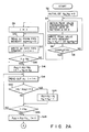
Magnetic disk 10 is rotated byspindle motor 8. Ondisk 10 the same pattern as the servo pattern shown in Fig. 3A is recorded. When a seek instruction is input toCPU 30, the initialization is performed in step S2. For example, the values NA and NB are set to be 0. Also, values AS and BS are set to be 0.Magnetic head 12 is subjected to a speed control for movement to a destination track. When the head reaches near to the destination track, the control is switched from the speed control to the positioning control as shown in step S2 and the following steps. Assume now thathead 12 is positioned onposition 2 with respect to the destination track. - In step S4, servo data 61-63 and 71-73 are read from
magnetic disk 10 byhead 12 to generate servo signal corresponding to servo data 61-63 and 71-73. The servo signal is amplified inamplifier 14, and the signal shown in Fig. 3C is obtained. The amplified servo signal is applied totiming extractor 16. Switch 15 responds a switch control signal fromtiming extractor 16 to apply signal components corresponding to servo data 61-63 in pattern A to peakhold circuit 18 and signal components corresponding to servo data 71-73 in pattern B to peakhold circuit 20. One of the signal components applied topeak hold circuit 18 is held therein in accordance with a hold control signal, and the held peak value is converted to digital data by A/D converter 22 in response to a conversion control signal fromtiming extractor 16. The converted peak values are stored intoFIFO memory 26 in response to a write control signal in step S6. At this time, the value NA indicative of the number of pieces of the servo data is incremented by one. The same processes are carried out for the servo signal components corresponding to servo data 71-73 in pattern B. In step S8, a decision is made as to whether or not the reading and writing operations have been completed for all the servo data. If NO in step S8, then the operations of steps S4 to S8 are repeated. If YES in step S8, then step S9 will be performed. - In step S9, a variable I is set to be "1". The number NA of the servo data 61-63 is stored in
register 324. In step S10, peak value AI is read fromFIFO memory 26 for addition to variable AS. In step S12, the read peak value AI is stored intomemory 26 again. At the same time, the variable I is incremented by one. Subsequently, a decision is made in step S14 as to whether the variable I is equal to the number NA of the servo data or not. If not equal, then the operations of steps S10 to S14 are repeated. If equal (YES) in step S14, then step S16 is carried out. - In step S16, an average value AAV (=AS/NA) for the servo data in pattern A is calculated. Subsequently, variable I is initialized to one, and value NA is set to variable KA. The sum value AS is stored in
register 322. In step S18, peak value AI is read fromFIFO memory 26 again, and variable I is incremented by one. In step S20, a decision is made as to whether or not an absolute value of a difference between peak value AI and average value AAV is larger than predetermined error E. If the absolute value is smaller than error E, then step S26 is carried out. If the absolute value is larger than the error, then step S24 is carried out so that sum value AS is read out ofregister 322 and peak value AI is subtracted from sum value AS. The result of the subtraction is stored inregister 322. Variable KA stored inregister 326 is decremented by one. - That is to say, of the peak values A61-A63 corresponding to the servo data 61-63, the peak values A61 and A63 are considered to fall within the margin of error E of average value AAV in step S20 and thus used for calculating the average value. On the other hand, peak value A62 due to the disturbance is excluded from the calculation of the average value because the result of the decision in step S20 based on the value A62 is YES.
- Subsequently, in step S26, a decision is made as to whether variable I is equal to number NA of data stored in
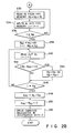
register 324. If not equal, the step S18 is carried out again. If equal, then a new average value AAV is calculated from sum value AS and variable KA and stored inregister 322. At the same time, variable I is set to be one. - In steps S30 through S48, the same processes as those in steps S10 through S28 are carried out for the servo data 71-73 in pattern B. In this way, average values AAV and BAV are obtained.
- In step S50, difference D between average values AAV and BAV is calculated, and a drive control signal is determined in accordance with difference
D. Carriage mechanism 34 is driven by the determined drive control signal. As a result, average value AAV of peak values A61-A63 and average value BAV of peak values B71-B73 are made equal to each other, so thatmagnetic heads - Next, a second embodiment of the magnetic disk driving apparatus of the present invention will be described.
- The arrangement of the second embodiment will first be described with reference to Fig. 4. In the second embodiment, like reference numerals are used to denote like portions in the first embodiment, and the description thereof will be excluded.
- In the second embodiment, peak values A61-A63 and B71-B73 corresponding to servo data 61-63 and 71-73 in servo patterns A and B are stored together in
FIFO memory 46 in accordance with a write control signal from timingextractor 44 similar toextractor 16.CPU 50 similar toCPU 30 calculates differences between A61 and B71; A62 and B72; A63 and B73, and then drivescarriage mechanism 34 in accordance with an average value CAV of the calculated differences. - In the operation of steps S60 through S66 shown in Fig. 5 the same processes as those in steps S2 through S8 in the first embodiment are performed. In the second embodiment,
single FIFO memory 46 is used, so that peak values A61-A63 and B71-B73 are alternately stored intoFIFO memory 46. If the storage of the servo data intoFIFO memory 46 is completed in step S66, then variable I is set to be one in step S67. - Steps S68 through S72 are the same as steps S10 through S14 in the first embodiment. In the first embodiment the peak values are separately added while, in the second embodiment, a difference between peak values A61 and B71 is first obtained and then the difference is added to value CS in step S68. If, in step S72, it is decided that the addition is completed, then average value CAV is calculated and value CS is stored in
register 482 inmemory 48 similar tomemory 32. Number N of the servo data has been stored inregister 484 in step S74. - When average value CAV is obtained, the same processes as those in steps S18 through S26 in the first embodiment are carried out for each difference obtained in step S68. As a result, even if error signals due to the disturbance, the deficiencies of
magnetic disk 10, or the like are output fromamplifier 14, they can be removed in steps S78 and S80. Sum value CS of normal differences alone is obtained in step S82, and then average value CAV is calculated in step S84. - In step S84, a drive control signal is determined in accordance with average value CAV of the differences.
Carriage mechanism 34 is driven in accordance with the determined drive control signal. As a result,magnetic heads
Claims (8)
detecting means (12 to 28; 12 to 22, 44 and 46) for detecting peak values of signal components corresponding to servo data read out from said magnetic disk by said magnetic head;
control means (30; 50) for generating a drive instruction in accordance with a plurality of selected peak values from among the detected peak values from said detecting means; and
driving means (34) for driving said magnetic head on the destination track in accordance with the drive instruction generated by said control means.
first selecting means (30), for calculating a first average value of first peak values of the detected peak values, and for selecting, from among the first peak values, said first selected peak values which fall within a predetermined value with respect to the first average value; and
second selecting means (30), for calculating a second average value of second peak values of the detected peak values, and for selecting, from among the second peak values, said second selected peak values which fall within the predetermined value with respect to the second average value.
means (30) for calculating a third average value from said first selected peak values;
means (30) for calculating a fourth average value from said second selected peak values;
difference calculating means (30) for calculating a difference between the third and fourth average values; and
generating means (30) for generating the drive instruction in accordance with the difference.
reading means (12, 14) for reading out the servo data from said magnetic disk, by means of said magnetic head, to generate the signal components;
timing extraction means (16) for extracting a switching control signal, first and second detect control signals, and first and second write control signals from the signal components;
first FIFO memory means (26), for storing first peak values of the detected peak values;
second FIFO memory means (28), for storing second peak values of the detected peak values;
first peak detecting means (18, 22), for detecting the first peak values from the signal components, in response to the first detect control signal from said timing extraction means, and for writing the detected first peak values into said first FIFO memory means, in response to the first write control signal from said timing extraction means;
second peak detecting means (20, 24), for detecting the second peak values from the signal components, in response to the second detect control signal from said timing extracting means, and for writing the detected second peak values into said second FIFO memory means, in response to the second write control signal from said timing extraction means; and
switching means (15) for selectively outputting the signal components to one of said first and second peak detecting means, in response to the switching control signal from said timing extraction means.
reading means (12, 14) for reading out the servo data from said magnetic disk, by means of said magnetic head, to generate the signal components;
timing extraction means (44) for extracting a hold control signal and a write control signal from the signal components;
FIFO memory means (46) for storing first and second peak values of the detected peak values; and
peak detecting means (18, 22) for detecting as the detected peak values the first and second peak values from the signal components, in response to the detect control signal from said timing extraction means, and for writing the first and second peak values into said FIFO memory means, in response to the write control signal from said timing extraction means.
means (50) for calculating the respective differences between the first and second peak values;
selecting means (50) for calculating an average value of the calculated respective differences, and for selecting from the calculated respective differences the plurality of selected differences which fall within a predetermined value with respect to the average value; and
means (50) for generating the drive instruction from the plurality of selected differences to output the generated instruction to said driving means.
Applications Claiming Priority (2)
| Application Number | Priority Date | Filing Date | Title |
|---|---|---|---|
| JP246055/87 | 1987-09-30 | ||
| JP62246055A JPH0677379B2 (en) | 1987-09-30 | 1987-09-30 | Disk device |
Publications (3)
| Publication Number | Publication Date |
|---|---|
| EP0310119A2 true EP0310119A2 (en) | 1989-04-05 |
| EP0310119A3 EP0310119A3 (en) | 1990-10-10 |
| EP0310119B1 EP0310119B1 (en) | 1994-01-26 |
Family
ID=17142791
Family Applications (1)
| Application Number | Title | Priority Date | Filing Date |
|---|---|---|---|
| EP88116212A Expired - Lifetime EP0310119B1 (en) | 1987-09-30 | 1988-09-30 | Method for positioning a magnetic head and magnetic disk driving apparatus for implementing the method |
Country Status (5)
| Country | Link |
|---|---|
| US (1) | US4907107A (en) |
| EP (1) | EP0310119B1 (en) |
| JP (1) | JPH0677379B2 (en) |
| KR (1) | KR920006123B1 (en) |
| DE (1) | DE3887424T2 (en) |
Cited By (3)
| Publication number | Priority date | Publication date | Assignee | Title |
|---|---|---|---|---|
| EP0556445A1 (en) * | 1991-10-01 | 1993-08-25 | Fujitsu Limited | Peak detector for magnetic disc drive track following |
| FR2699721A1 (en) * | 1992-12-23 | 1994-06-24 | Raymond Engineering | Unit for operating magnetic disks, especially a memory unit. |
| US6088188A (en) * | 1997-02-10 | 2000-07-11 | International Business Machines Corporation | System and method for determining when hard disk drive power amplifier is saturated |
Families Citing this family (7)
| Publication number | Priority date | Publication date | Assignee | Title |
|---|---|---|---|---|
| EP0507907B1 (en) * | 1990-09-18 | 1999-01-13 | Rodime PLC | Digital servo control system for use in disk drives |
| US5305160A (en) * | 1991-07-31 | 1994-04-19 | Seagate Technology, Inc. | Compensating for variations in torque capability of voice coil motors |
| US5305447A (en) * | 1991-07-31 | 1994-04-19 | Seagate Technology, Inc. | Multi-task operating system for a disc drive |
| US5377131A (en) * | 1992-12-31 | 1994-12-27 | International Business Machines Corporation | Digital amplitude estimator |
| US5563859A (en) * | 1993-04-07 | 1996-10-08 | Matsushita Electric Industrial Co., Ltd. | Method for simultaneous recording and playback from both sides of a recording medium |
| US5625508A (en) * | 1993-08-26 | 1997-04-29 | International Business Machines Corporation | Method and apparatus for servo demodulation in a direct access storage device |
| JP5968132B2 (en) * | 2012-07-11 | 2016-08-10 | キヤノン株式会社 | Image processing apparatus, image processing method, and program |
Citations (4)
| Publication number | Priority date | Publication date | Assignee | Title |
|---|---|---|---|---|
| US4380034A (en) * | 1980-09-26 | 1983-04-12 | Magnetic Peripherals Inc. | Track centering servo pulse noise filter |
| JPS6050774A (en) * | 1983-08-31 | 1985-03-20 | Toshiba Corp | Generation system of magnetic head positioning information |
| JPS62259269A (en) * | 1986-05-06 | 1987-11-11 | Matsushita Electric Ind Co Ltd | Tracking controller |
| JPS63153772A (en) * | 1986-12-18 | 1988-06-27 | Fujitsu Ltd | Servo system |
Family Cites Families (3)
| Publication number | Priority date | Publication date | Assignee | Title |
|---|---|---|---|---|
| US4419701A (en) * | 1981-09-21 | 1983-12-06 | Quantum Corporation | Data transducer position control system for rotating disk data storage equipment |
| WO1983004133A1 (en) * | 1982-05-17 | 1983-11-24 | International Business Corporation | Sector servo seek control |
| US4737869A (en) * | 1985-03-20 | 1988-04-12 | Kabushiki Kaisha Toshiba | Magnetic disk having data area and index servo area and servo system for positioning read/write head on magnetic disk |
-
1987
- 1987-09-30 JP JP62246055A patent/JPH0677379B2/en not_active Expired - Fee Related
-
1988
- 1988-09-29 US US07/250,857 patent/US4907107A/en not_active Expired - Lifetime
- 1988-09-30 KR KR1019880012816A patent/KR920006123B1/en not_active IP Right Cessation
- 1988-09-30 EP EP88116212A patent/EP0310119B1/en not_active Expired - Lifetime
- 1988-09-30 DE DE88116212T patent/DE3887424T2/en not_active Expired - Lifetime
Patent Citations (4)
| Publication number | Priority date | Publication date | Assignee | Title |
|---|---|---|---|---|
| US4380034A (en) * | 1980-09-26 | 1983-04-12 | Magnetic Peripherals Inc. | Track centering servo pulse noise filter |
| JPS6050774A (en) * | 1983-08-31 | 1985-03-20 | Toshiba Corp | Generation system of magnetic head positioning information |
| JPS62259269A (en) * | 1986-05-06 | 1987-11-11 | Matsushita Electric Ind Co Ltd | Tracking controller |
| JPS63153772A (en) * | 1986-12-18 | 1988-06-27 | Fujitsu Ltd | Servo system |
Non-Patent Citations (3)
| Title |
|---|
| IBM TECHNICAL DISCLOSURE BULLETIN. vol. 23, no. 7A, December 1980, NEW YORK US pages 2713 - 2713; J.C.DENNISON ET AL: "ERRONEOUS POSITION ERROR SIGNAL ACCOMODATION" * |
| PATENT ABSTRACTS OF JAPAN vol. 12, no. 138 (P-695)(2985) 27 April 1988, & JP-A-62 259269 (MATSUSHITA) 11 November 1987, * |
| PATENT ABSTRACTS OF JAPAN vol. 9, no. 177 (P-375)(1900) 23 July 1985, & JP-A-60 50774 (TOSHIBA) 20 March 1985, * |
Cited By (4)
| Publication number | Priority date | Publication date | Assignee | Title |
|---|---|---|---|---|
| EP0556445A1 (en) * | 1991-10-01 | 1993-08-25 | Fujitsu Limited | Peak detector for magnetic disc drive track following |
| US5455720A (en) * | 1991-10-01 | 1995-10-03 | Fujitsu Limited | Offset and gain error discriminator |
| FR2699721A1 (en) * | 1992-12-23 | 1994-06-24 | Raymond Engineering | Unit for operating magnetic disks, especially a memory unit. |
| US6088188A (en) * | 1997-02-10 | 2000-07-11 | International Business Machines Corporation | System and method for determining when hard disk drive power amplifier is saturated |
Also Published As
| Publication number | Publication date |
|---|---|
| EP0310119B1 (en) | 1994-01-26 |
| US4907107A (en) | 1990-03-06 |
| EP0310119A3 (en) | 1990-10-10 |
| JPS6489089A (en) | 1989-04-03 |
| KR920006123B1 (en) | 1992-07-27 |
| DE3887424D1 (en) | 1994-03-10 |
| DE3887424T2 (en) | 1994-05-11 |
| KR890005710A (en) | 1989-05-16 |
| JPH0677379B2 (en) | 1994-09-28 |
Similar Documents
| Publication | Publication Date | Title |
|---|---|---|
| US4631606A (en) | System for detecting the position of a read-write head on a disk recording medium having servo sectors with three or more servo patterns | |
| US8559125B2 (en) | Seamless and untrimmed primary servo burst with multiple secondary servo bursts | |
| EP0108060B1 (en) | Sector servo seek control | |
| EP0485704A2 (en) | Disk drive servosystem using gray code | |
| JP2593437B2 (en) | Servo positioning device for magnetic disk | |
| EP0310119A2 (en) | Method for positioning a magnetic head and magnetic disk driving apparatus for implementing the method | |
| EP0492774B1 (en) | Method and system for correcting offset of head position signal | |
| JPS583158A (en) | Head positioning servo apparatus | |
| US5235576A (en) | Optical disc apparatus | |
| US6172839B1 (en) | Technique for measuring the position error signal of a disk drive | |
| KR0131412B1 (en) | Head position detecting method in digital servo controlling hdd | |
| US5822144A (en) | Apparatus and method for adjusting positional sensitivity of disk unit | |
| US5146374A (en) | Method and apparatus for determining track position of a head on a recording medium | |
| JP2600560B2 (en) | Magnetic recording / reproducing device | |
| JPH0458113B2 (en) | ||
| JPH0330157A (en) | Positioning controller for magnetic disk device | |
| JPH05101566A (en) | Magnetic disk device | |
| KR100449684B1 (en) | Method for recording two burst signals in a hard disk drive and a track following method, especially concerned with exactly and quickly track-following a head on a specific track in order to read data from the corresponding track of a magnetic disk | |
| JPH03113783A (en) | Control method for magnetic disk device | |
| JP2982279B2 (en) | Offset method in seek control | |
| JPH02304777A (en) | Controller for magnetic disk device | |
| JPH1074371A (en) | Magnetic disk device | |
| JPH02149984A (en) | Magnetic disk device | |
| JP2914971B2 (en) | Magnetic disk drive | |
| JPH02123576A (en) | Flexible disk device |
Legal Events
| Date | Code | Title | Description |
|---|---|---|---|
| PUAI | Public reference made under article 153(3) epc to a published international application that has entered the european phase |
Free format text: ORIGINAL CODE: 0009012 |
|
| 17P | Request for examination filed |
Effective date: 19881027 |
|
| AK | Designated contracting states |
Kind code of ref document: A2 Designated state(s): DE FR GB NL |
|
| PUAL | Search report despatched |
Free format text: ORIGINAL CODE: 0009013 |
|
| AK | Designated contracting states |
Kind code of ref document: A3 Designated state(s): DE FR GB NL |
|
| 17Q | First examination report despatched |
Effective date: 19920423 |
|
| RBV | Designated contracting states (corrected) |
Designated state(s): DE GB |
|
| GRAA | (expected) grant |
Free format text: ORIGINAL CODE: 0009210 |
|
| AK | Designated contracting states |
Kind code of ref document: B1 Designated state(s): DE GB |
|
| REF | Corresponds to: |
Ref document number: 3887424 Country of ref document: DE Date of ref document: 19940310 |
|
| PLBE | No opposition filed within time limit |
Free format text: ORIGINAL CODE: 0009261 |
|
| STAA | Information on the status of an ep patent application or granted ep patent |
Free format text: STATUS: NO OPPOSITION FILED WITHIN TIME LIMIT |
|
| 26N | No opposition filed | ||
| REG | Reference to a national code |
Ref country code: GB Ref legal event code: IF02 |
|
| PGFP | Annual fee paid to national office [announced via postgrant information from national office to epo] |
Ref country code: DE Payment date: 20070927 Year of fee payment: 20 |
|
| PGFP | Annual fee paid to national office [announced via postgrant information from national office to epo] |
Ref country code: GB Payment date: 20070926 Year of fee payment: 20 |
|
| REG | Reference to a national code |
Ref country code: GB Ref legal event code: PE20 Expiry date: 20080929 |
|
| PG25 | Lapsed in a contracting state [announced via postgrant information from national office to epo] |
Ref country code: GB Free format text: LAPSE BECAUSE OF EXPIRATION OF PROTECTION Effective date: 20080929 |