EP0309997A2 - Data reading or writing method and apparatus - Google Patents
Data reading or writing method and apparatus Download PDFInfo
- Publication number
- EP0309997A2 EP0309997A2 EP88115892A EP88115892A EP0309997A2 EP 0309997 A2 EP0309997 A2 EP 0309997A2 EP 88115892 A EP88115892 A EP 88115892A EP 88115892 A EP88115892 A EP 88115892A EP 0309997 A2 EP0309997 A2 EP 0309997A2
- Authority
- EP
- European Patent Office
- Prior art keywords
- reading
- head
- writing
- maximum
- speed
- Prior art date
- Legal status (The legal status is an assumption and is not a legal conclusion. Google has not performed a legal analysis and makes no representation as to the accuracy of the status listed.)
- Granted
Links
Images


Classifications
-
- H—ELECTRICITY
- H04—ELECTRIC COMMUNICATION TECHNIQUE
- H04N—PICTORIAL COMMUNICATION, e.g. TELEVISION
- H04N1/00—Scanning, transmission or reproduction of documents or the like, e.g. facsimile transmission; Details thereof
- H04N1/04—Scanning arrangements, i.e. arrangements for the displacement of active reading or reproducing elements relative to the original or reproducing medium, or vice versa
- H04N1/0402—Scanning different formats; Scanning with different densities of dots per unit length, e.g. different numbers of dots per inch (dpi); Conversion of scanning standards
- H04N1/0405—Different formats, e.g. A3 and A4
-
- H—ELECTRICITY
- H04—ELECTRIC COMMUNICATION TECHNIQUE
- H04N—PICTORIAL COMMUNICATION, e.g. TELEVISION
- H04N1/00—Scanning, transmission or reproduction of documents or the like, e.g. facsimile transmission; Details thereof
- H04N1/04—Scanning arrangements, i.e. arrangements for the displacement of active reading or reproducing elements relative to the original or reproducing medium, or vice versa
- H04N1/0402—Scanning different formats; Scanning with different densities of dots per unit length, e.g. different numbers of dots per inch (dpi); Conversion of scanning standards
- H04N1/042—Details of the method used
- H04N1/0443—Varying the scanning velocity or position
Definitions
- the present invention relates to a reading or writing method and apparatus thereof, and more particularly to a method and an apparatus for reading or writing data by driving a reading/writing head, for example, for use in a serial type of facsimile system.
- a movable unit serving as a reading/writing head has a unidimensional solid-state image sensor and a heating element for thermal recording which are arranged according to the direction of transport of documents and recording paper.
- the movable unit performs a reading or writing operation while traveling in a direction perpendicular to the transport direction (see, for example, U.S. Patent No. 4,564,847 and Unexamined Japanese Patent Publication SHO-59-228462).
- the serial-type facsimile apparatus has the advantage of being inexpensive to manufacture since there is no need to use expensive electronic parts such as a line sensor extending over the entire width of documents and a heating element extending over the entire width of the recording paper.
- the movable unit which is mechanically driven, gives off mechanical noise. Especially in a direction opposite to the reading or writing direction, the movable unit is driven at a high speed, so that the mechanical noise during the travel and an impact noise on stopping are considered to be a nuisance.
- Fig. 4 is a diagram showing the relationship between the speed of travel of the movable unit and time in the reading operation of a conventional facsimile apparatus.
- the speed of the movable unit for a document of large size is indicated in the phantom line.
- the movable unit starts to travel from a reference position at the start of a period T5, reads the document while traveling over the period T5 and stops on traveling the dimension of the document.
- the unit is thereafter returned to the reference position over a period of T8.
- the speed of the movable unit for a document of small size is represented by a solid line.
- the unit starts to travel from the reference position with the start of a period T6, reads the document while traveling over the period T6 and stops upon traveling the dimension of the document.
- the unit thereafter returns to the reference position over a period of T7. When returning to the reference position, the unit travels at a particular speed regardless of the size of documents.
- the present invention provides a reading or writing method for reading data on a medium or writing data thereon by reciprocatively driving a reading/writing head over the medium, the method comprising driving the head forward at a predermined speed at all times, and returning the head at a predetermined maximum speed when the reading or writing length is a maximum, or at a speed lower than the maximum speed when the reading or writing length is shorter than the maximum so as to complete the reciprocation of the head within the same period as when the reading or writing length is the maximum.
- the present invention further provides a reading/writing apparatus comprising: transport means for transporting a medium in one direction, a head for reading data from the medium or writing data thereon, head drive means for reciprocatively driving the head over the medium perpendicular to the direction of transport of the medium, communication means for sending out the data read by the head and receiving from outside the data to be written on the medium to feed the data to the head, sensor means for detecting the size of the medium, means forjudging the length of reading or writing by the head for the medium size detected by the sensor means or from the data received by the communication means, and control means for controlling the transport means and the head drive means in synchronism to drive the head forward at a predetermined speed at all times and to return the head at a predetermined maximum speed when the reading or writing length determined by the judging means is at a maximum, or at a speed lower than the maximum speed when the reading or writing length is shorter than the maximum so as to complete the reciprocation of the head within the same period as when the reading or writing length is the maximum.
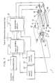
- Fig. 1 is a block diagram schematically showing the construction of a facsimile apparatus 1 of the serial type embodying the invention
- Fig. 2 is a perspective view showing the appearance of the facsimile apparatus.
- the facsimile apparatus 1 comprises a stepping motor 25 and a movable unit 17 serving as a reading/writing head.
- the movable unit 17 includes a line sensor 5 employed parallel to the direction 28 of transport of a document 13 or recording paper 10, and a heating element 6 for thermal recording.
- a control unit 16 is divided into a main control circuit 20 for effecting control, for example, for data transmission, and a subcontrol circuit 21 for primarily controlling mechanical drive means.
- the document 13 is scanned by the line sensor and read over a specified width (e.g. 16 mm) at every stroke.
- the output of the line sensor 5 is fed to the main control circuit 20 via an image pickup circuit 22.
- the main control circuit 20 transmits the data, for example, to a telephone circuit through a transmission circuit 24 for encoding or composing signals.
- the main control circuit 20 feeds a synchronizing signal to the subcontrol circuit 21.
- the signals received are delivered from the transmission circuit 24 to the main control circuit 20, which in turn feeds the signals to the heating element 6 via an image control circuit 23 to write the data on the paper 10.
- the image control circuit 23 feeds a synchronizing signal to the subcontrol circuit 21.
- the subcontrol circuit 21 controls a stepping motor 26 or 27 in response to the synchronizing signal from the main control circuit 20 or the image control circuit 23.
- the stepping motors 26 and 27 drive rollers 3 and 4, respectively, to transport the document 13 and the paper 10 in the direction of arrow 28.
- the movable unit 17 reads or writes the data while traveling from a reference position.
- the power of the stepping motor 25 is transmitted to the movable unit 17 by means of a wire 14 reeved around the motor 25 and a pulley 15, whereby the movable unit 17 is driven.
- the subcontrol circuit 21 feeds a pulse signal to the stepping motor 25 to thereby drive the stepping motor 25.
- the movable unit 17 travels a given distance in response to one pulse delivered from the subcontrol circuit 21.
- the document 13 is inserted into the apparatus 1 through an inlet 8.
- Guides 7 are movable sidewise in conformity with the size of the document 13.
- a sensor (not shown), such as a microswitch, provided in connection with the guide 7 gives the main control circuit 20 a signal indicating the size of the document 13.
- the main control circuit 20 determines the speed of travel of the movable unit 17 in the direction of the arrow 12 according to the size and then feeds a signal representing the speed to the subcontrol circuit 21.
- the subcontrol circuit 21 controls the speed of rotation of the stepping motor 25 by varying the number of pulses to be given to the motor 25 per unit time and thereby vary the speed of travel of the movable unit 17 in the direction 12.
- Fig. 3 is a diagram showing the relationship between the travel speed of the movable unit 17 and time during the reading operation of the facsimile apparatus 1.
- the operation will be described with reference to Fig. 3.
- the speed of the movable unit 17 for a document 13 of large size is indicated in a phantom line.
- the movable unit 17 starts to travel from the reference position toward the direction of arrow 11 in Fig. 1 with the start of a period T1, reads the document while traveling over the period T1 and stops upon traveling the dimension of the document. Subsequently, the unit is driven in the direction of arrow 12 over a period of T2 to return to the reference position. Since the document size is large, the unit is unable to return to the reference position within the scanning time which is limited as already stated, unless the unit travels at a high speed at this time. The above operation is repeated for the reading of the document 13.
- the speed of the movable unit 17 for a document of small size is indicated in a solid line in Fig. 3.
- the unit 17 reads the document while traveling toward the direction of arrow 11.
- the unit thereafter travels at a low speed toward the direction of arrow 12 during a period of T4 to return to the reference position. Since the speed of the return travel is low as illustrated in Fig. 3, there is little or no useless waiting time.
- the movable unit 17 is driven at a low speed in the direction of arrow 12 when the apparatus 1 is used for documents of normal size and frequency, i.e. for those having a size smaller than the maximum size which can be handled by the apparatus.
- This serves to inhibit the mechanical noise emanating from the stepping motor 25 and the like, also inhibiting the impact noise otherwise produced when the unit is stopped abruptly at the reference position.
- the above feature shortens the rest period of the stepping motor 25, consequently improving the duty cycle of the motor to diminish the power consumption.
- the main control circuit 20 Upon receiving a signal from the telephone circuit of the like in this case, the main control circuit 20 feeds a synchronizing signal to the subcontrol circuit 21, which in turn causes the movable unit 17 to travel from the reference position toward the direction of arrow 11 for writing. At the same time, the main control circuit 20 detects from the received signal the distance the movable unit 17 is to be driven in the direction of arrow 11 and determines the speed of travel in the direction of arrow 12 in corresponding relation thereto in the same manner as above. The circuit 20 gives the subcontrol circuit 21 a signal representing the optimal speed. In this way the speed of return of the movable unit 17 is controlled for the writing operation.
- the speed of of travel of the reading/writing head in a direction opposite to the reading or writing direction is determined according to the distance the head is traveled in the reading or writing direction so that the period of reciprocation of the head will be a specified value.
Abstract
Description
- The present invention relates to a reading or writing method and apparatus thereof, and more particularly to a method and an apparatus for reading or writing data by driving a reading/writing head, for example, for use in a serial type of facsimile system.
- With serial-type facsimile apparatus, a movable unit serving as a reading/writing head has a unidimensional solid-state image sensor and a heating element for thermal recording which are arranged according to the direction of transport of documents and recording paper. The movable unit performs a reading or writing operation while traveling in a direction perpendicular to the transport direction (see, for example, U.S. Patent No. 4,564,847 and Unexamined Japanese Patent Publication SHO-59-228462).
- Accordingly, the serial-type facsimile apparatus has the advantage of being inexpensive to manufacture since there is no need to use expensive electronic parts such as a line sensor extending over the entire width of documents and a heating element extending over the entire width of the recording paper.
- However, the movable unit, which is mechanically driven, gives off mechanical noise. Especially in a direction opposite to the reading or writing direction, the movable unit is driven at a high speed, so that the mechanical noise during the travel and an impact noise on stopping are considered to be a nuisance.
- On the recommendation of CCITT (The International Telegraph and Telephone Consultative Committee), a limitation has been imposed on the communication time per line of the facsimile system, whereby the scanning time per stroke of the movable unit is limited. Accordingly, during the return travel (without reading or writing), the movable unit is driven at a particular speed depending on the maximum size of documents being used.
- Fig. 4 is a diagram showing the relationship between the speed of travel of the movable unit and time in the reading operation of a conventional facsimile apparatus.
- The speed of the movable unit for a document of large size is indicated in the phantom line. For this document, the movable unit starts to travel from a reference position at the start of a period T5, reads the document while traveling over the period T5 and stops on traveling the dimension of the document. The unit is thereafter returned to the reference position over a period of T8.
- The speed of the movable unit for a document of small size is represented by a solid line. The unit starts to travel from the reference position with the start of a period T6, reads the document while traveling over the period T6 and stops upon traveling the dimension of the document. The unit thereafter returns to the reference position over a period of T7. When returning to the reference position, the unit travels at a particular speed regardless of the size of documents.
- Conventional serial-type facsimile apparatus are generally adapted for use with documents ranging in width from A5 size (148 mm) to A3 size (297 mm). While the documents actually used have varying sizes, documents of maximum size are used rather infrequently. However, even if documents of small size are used, the head is returned at a particular high speed at all times as already stated, consequently producing the same noise as when those of maximum size are used.
- The present invention provides a reading or writing method for reading data on a medium or writing data thereon by reciprocatively driving a reading/writing head over the medium, the method comprising driving the head forward at a predermined speed at all times, and returning the head at a predetermined maximum speed when the reading or writing length is a maximum, or at a speed lower than the maximum speed when the reading or writing length is shorter than the maximum so as to complete the reciprocation of the head within the same period as when the reading or writing length is the maximum.
- The present invention further provides a reading/writing apparatus comprising:
transport means for transporting a medium in one direction,
a head for reading data from the medium or writing data thereon,
head drive means for reciprocatively driving the head over the medium perpendicular to the direction of transport of the medium,
communication means for sending out the data read by the head and receiving from outside the data to be written on the medium to feed the data to the head, sensor means for detecting the size of the medium, means forjudging the length of reading or writing by the head for the medium size detected by the sensor means or from the data received by the communication means, and
control means for controlling the transport means and the head drive means in synchronism to drive the head forward at a predetermined speed at all times and to return the head at a predetermined maximum speed when the reading or writing length determined by the judging means is at a maximum, or at a speed lower than the maximum speed when the reading or writing length is shorter than the maximum so as to complete the reciprocation of the head within the same period as when the reading or writing length is the maximum. -
- Fig. 1 is a block diagram schematically showing the construction of a facsimile apparatus embodying the invention;
- Fig. 2 is a perspective view showing the appearance of the facsimile apparatus;
- Fig. 3 is a diagram showing the relationship between the speed of travel of a movable unit in the facsimile apparatus; and
- Fig. 4 is a diagram showing the relationship between the speed of travel of a movable unit in a conventional facsimile apparatus.
- Fig. 1 is a block diagram schematically showing the construction of a facsimile apparatus 1 of the serial type embodying the invention, and Fig. 2 is a perspective view showing the appearance of the facsimile apparatus.
- The facsimile apparatus 1 comprises a
stepping motor 25 and amovable unit 17 serving as a reading/writing head. Themovable unit 17 includes a line sensor 5 employed parallel to thedirection 28 of transport of adocument 13 orrecording paper 10, and a heating element 6 for thermal recording. Acontrol unit 16 is divided into amain control circuit 20 for effecting control, for example, for data transmission, and asubcontrol circuit 21 for primarily controlling mechanical drive means. - When a button or the like on an
operation panel 2 of the apparatus 1 is depressed to read thedocument 13 and transmit the data read, thedocument 13 is scanned by the line sensor and read over a specified width (e.g. 16 mm) at every stroke. The output of the line sensor 5 is fed to themain control circuit 20 via animage pickup circuit 22. Themain control circuit 20 transmits the data, for example, to a telephone circuit through atransmission circuit 24 for encoding or composing signals. At the same time, themain control circuit 20 feeds a synchronizing signal to thesubcontrol circuit 21. - When signals are received from the telephone circuit or the like for writing data on the
recording paper 10, the signals received are delivered from thetransmission circuit 24 to themain control circuit 20, which in turn feeds the signals to the heating element 6 via animage control circuit 23 to write the data on thepaper 10. At this time, theimage control circuit 23 feeds a synchronizing signal to thesubcontrol circuit 21. - For the transport of the
document 13 or therecording paper 10, thesubcontrol circuit 21 controls astepping motor main control circuit 20 or theimage control circuit 23. Thestepping motors drive rollers 3 and 4, respectively, to transport thedocument 13 and thepaper 10 in the direction ofarrow 28. - With the facsimile apparatus 1 described, the
movable unit 17 reads or writes the data while traveling from a reference position. The power of the steppingmotor 25 is transmitted to themovable unit 17 by means of awire 14 reeved around themotor 25 and apulley 15, whereby themovable unit 17 is driven. - The
subcontrol circuit 21 feeds a pulse signal to the steppingmotor 25 to thereby drive the steppingmotor 25. Themovable unit 17 travels a given distance in response to one pulse delivered from thesubcontrol circuit 21. - The
document 13 is inserted into the apparatus 1 through an inlet 8. Guides 7 are movable sidewise in conformity with the size of thedocument 13. A sensor (not shown), such as a microswitch, provided in connection with the guide 7 gives the main control circuit 20 a signal indicating the size of thedocument 13. - Thus recognizing the size of the
document 13, themain control circuit 20 determines the speed of travel of themovable unit 17 in the direction of thearrow 12 according to the size and then feeds a signal representing the speed to thesubcontrol circuit 21. Thesubcontrol circuit 21 controls the speed of rotation of thestepping motor 25 by varying the number of pulses to be given to themotor 25 per unit time and thereby vary the speed of travel of themovable unit 17 in thedirection 12. - Fig. 3 is a diagram showing the relationship between the travel speed of the
movable unit 17 and time during the reading operation of the facsimile apparatus 1. The operation will be described with reference to Fig. 3. The speed of themovable unit 17 for adocument 13 of large size is indicated in a phantom line. For this document, themovable unit 17 starts to travel from the reference position toward the direction ofarrow 11 in Fig. 1 with the start of a period T1, reads the document while traveling over the period T1 and stops upon traveling the dimension of the document. Subsequently, the unit is driven in the direction ofarrow 12 over a period of T2 to return to the reference position. Since the document size is large, the unit is unable to return to the reference position within the scanning time which is limited as already stated, unless the unit travels at a high speed at this time. The above operation is repeated for the reading of thedocument 13. - The speed of the
movable unit 17 for a document of small size is indicated in a solid line in Fig. 3. During a period T3, theunit 17 reads the document while traveling toward the direction ofarrow 11. The unit thereafter travels at a low speed toward the direction ofarrow 12 during a period of T4 to return to the reference position. Since the speed of the return travel is low as illustrated in Fig. 3, there is little or no useless waiting time. - Thus, the
movable unit 17 is driven at a low speed in the direction ofarrow 12 when the apparatus 1 is used for documents of normal size and frequency, i.e. for those having a size smaller than the maximum size which can be handled by the apparatus. This serves to inhibit the mechanical noise emanating from the steppingmotor 25 and the like, also inhibiting the impact noise otherwise produced when the unit is stopped abruptly at the reference position. Furthermore, the above feature shortens the rest period of the steppingmotor 25, consequently improving the duty cycle of the motor to diminish the power consumption. - Although the reading operation of the above embodiment has been described, the writing operation thereof can be similarly controlled according to the invention. Upon receiving a signal from the telephone circuit of the like in this case, the
main control circuit 20 feeds a synchronizing signal to thesubcontrol circuit 21, which in turn causes themovable unit 17 to travel from the reference position toward the direction ofarrow 11 for writing. At the same time, themain control circuit 20 detects from the received signal the distance themovable unit 17 is to be driven in the direction ofarrow 11 and determines the speed of travel in the direction ofarrow 12 in corresponding relation thereto in the same manner as above. Thecircuit 20 gives the subcontrol circuit 21 a signal representing the optimal speed. In this way the speed of return of themovable unit 17 is controlled for the writing operation. - Thus, according to the present invention, the speed of of travel of the reading/writing head in a direction opposite to the reading or writing direction is determined according to the distance the head is traveled in the reading or writing direction so that the period of reciprocation of the head will be a specified value.
- Consequently, the speed of travel is lowered when the reading or writing length is shortened and thus minimizes the running noise and impact noise on stopping. It is also possible to improve the performance of the motor for driving the head to assure reduced power consumption.
Claims (7)
transport means (26,3; 27,4) for transporting a medium (13; 10)in one direction,
a head (17) for reading data from the medium or writing data thereon,
head drive means (25, 14, 15) for reciprocatively driving the head over the medium perpendicular to the direction of transport of the medium,
communication means (24) for sending out the data read by the head and receiving from outside the data to be written on the medium to feed the data to the head,sensor means (5) for detecting the size of the medium,means for judging the length of reading or writing by the head from the medium size detected by the sensor means or from the data re ceived by the communication means, and
control means (16) for controlling the transport means and the head drive means in synchronism to drive the head forward at a predetermined speed at all times and to return the head at a predetermined maximum speed when the reading or writing length determined by the judging means is at a maximum, or at a speed lower than the maximum speed when the reading or writing length is shorter than the maximum so as to complete the reciprocation of the head within the same period as when the reading or writing length is the maximum.
Applications Claiming Priority (2)
| Application Number | Priority Date | Filing Date | Title |
|---|---|---|---|
| JP247629/87 | 1987-09-30 | ||
| JP62247629A JPH0797810B2 (en) | 1987-09-30 | 1987-09-30 | Facsimile read / write head drive system |
Publications (3)
| Publication Number | Publication Date |
|---|---|
| EP0309997A2 true EP0309997A2 (en) | 1989-04-05 |
| EP0309997A3 EP0309997A3 (en) | 1991-03-20 |
| EP0309997B1 EP0309997B1 (en) | 1994-05-11 |
Family
ID=17166353
Family Applications (1)
| Application Number | Title | Priority Date | Filing Date |
|---|---|---|---|
| EP88115892A Expired - Lifetime EP0309997B1 (en) | 1987-09-30 | 1988-09-27 | Data reading or writing method and apparatus |
Country Status (4)
| Country | Link |
|---|---|
| US (1) | US4905090A (en) |
| EP (1) | EP0309997B1 (en) |
| JP (1) | JPH0797810B2 (en) |
| DE (1) | DE3889512T2 (en) |
Cited By (2)
| Publication number | Priority date | Publication date | Assignee | Title |
|---|---|---|---|---|
| EP0465216A2 (en) * | 1990-07-02 | 1992-01-08 | Xerox Corporation | Compact read/write scanner |
| EP0465213A2 (en) * | 1990-07-02 | 1992-01-08 | Xerox Corporation | Input and output scanner |
Families Citing this family (7)
| Publication number | Priority date | Publication date | Assignee | Title |
|---|---|---|---|---|
| US5047870A (en) * | 1988-03-17 | 1991-09-10 | Optum Corporation | Image reproduction system utilizing single operation scanning/reproducing |
| CA2027440C (en) * | 1989-11-08 | 1995-07-04 | Nicholas K. Sheridon | Paper-like computer output display and scanning system therefor |
| KR910019383A (en) * | 1990-04-12 | 1991-11-30 | 고바야시 쥰 | Original Reading Device |
| US5267056A (en) * | 1991-01-03 | 1993-11-30 | Xerox Corporation | Right reading image for read/write components co-mounted on a single X-Y carriage |
| US5822468A (en) * | 1992-03-10 | 1998-10-13 | Ivp Integrated Vision Products Ab | Method of carrying out picture processing operations upon a two-dimensional picture and a device for carrying out said method |
| US6717537B1 (en) | 2001-06-26 | 2004-04-06 | Sonic Innovations, Inc. | Method and apparatus for minimizing latency in digital signal processing systems |
| US20050128510A1 (en) * | 2003-12-16 | 2005-06-16 | Campbell Michael C. | Method for selecting images for action by an imaging apparatus |
Citations (2)
| Publication number | Priority date | Publication date | Assignee | Title |
|---|---|---|---|---|
| DE3439144A1 (en) * | 1983-10-26 | 1985-05-09 | Canon K.K., Tokio/Tokyo | IMAGE RECORDING DEVICE |
| US4613245A (en) * | 1983-08-22 | 1986-09-23 | Seikosha Co., Ltd. | Device for controlling the carriage return of a lead screw driven printing head |
Family Cites Families (2)
| Publication number | Priority date | Publication date | Assignee | Title |
|---|---|---|---|---|
| JPS52142916A (en) * | 1976-05-25 | 1977-11-29 | Kokusai Denshin Denwa Co Ltd | Recording system |
| JPS6115135A (en) * | 1984-07-02 | 1986-01-23 | Sanyo Electric Co Ltd | Electronic copying machine |
-
1987
- 1987-09-30 JP JP62247629A patent/JPH0797810B2/en not_active Expired - Fee Related
-
1988
- 1988-09-27 EP EP88115892A patent/EP0309997B1/en not_active Expired - Lifetime
- 1988-09-27 DE DE3889512T patent/DE3889512T2/en not_active Expired - Fee Related
- 1988-09-28 US US07/250,410 patent/US4905090A/en not_active Expired - Lifetime
Patent Citations (2)
| Publication number | Priority date | Publication date | Assignee | Title |
|---|---|---|---|---|
| US4613245A (en) * | 1983-08-22 | 1986-09-23 | Seikosha Co., Ltd. | Device for controlling the carriage return of a lead screw driven printing head |
| DE3439144A1 (en) * | 1983-10-26 | 1985-05-09 | Canon K.K., Tokio/Tokyo | IMAGE RECORDING DEVICE |
Cited By (4)
| Publication number | Priority date | Publication date | Assignee | Title |
|---|---|---|---|---|
| EP0465216A2 (en) * | 1990-07-02 | 1992-01-08 | Xerox Corporation | Compact read/write scanner |
| EP0465213A2 (en) * | 1990-07-02 | 1992-01-08 | Xerox Corporation | Input and output scanner |
| EP0465216A3 (en) * | 1990-07-02 | 1992-08-05 | Xerox Corporation | Compact read/write scanner |
| EP0465213A3 (en) * | 1990-07-02 | 1992-08-26 | Xerox Corporation | Input and output scanner |
Also Published As
| Publication number | Publication date |
|---|---|
| JPS6490670A (en) | 1989-04-07 |
| EP0309997A3 (en) | 1991-03-20 |
| EP0309997B1 (en) | 1994-05-11 |
| US4905090A (en) | 1990-02-27 |
| DE3889512T2 (en) | 1994-12-08 |
| DE3889512D1 (en) | 1994-06-16 |
| JPH0797810B2 (en) | 1995-10-18 |
Similar Documents
| Publication | Publication Date | Title |
|---|---|---|
| US4631596A (en) | Image communications apparatus for long-size copy image | |
| US4386373A (en) | Facsimile apparatus | |
| US4905090A (en) | Reading or writing method and apparatus thereof | |
| US6178015B1 (en) | Apparatus and method for increasing the scan accuracy and quality of the flatbed scanner by using close loop control | |
| EP0655859B1 (en) | Data processing method and apparatus | |
| US5775821A (en) | Ribbon cassette for a printing apparatus | |
| EP0369824A3 (en) | Image reading apparatus | |
| EP0391276B1 (en) | Printer capable of printing at regular time intervals | |
| JP2884561B2 (en) | Image processing device | |
| EP0606076B1 (en) | Reader for a facsimile apparatus | |
| JPS57112175A (en) | System for transmission of facsimile information | |
| JP3077337B2 (en) | Scanning method for scanning originals | |
| JPH05328061A (en) | Facsimile equipment | |
| JP3307778B2 (en) | Image recording method by serial printer | |
| EP0413334A2 (en) | Printing apparatus and facsimile equipped therewith | |
| JPS59178073A (en) | Device for scanning and recording picture | |
| JPS61219261A (en) | Image reader | |
| JP3201557B2 (en) | Facsimile machine | |
| JPS595775A (en) | Data recording method of facsimile equipment | |
| JPH0976487A (en) | Recording device | |
| JPH04270553A (en) | Facsimile equipment | |
| JPH07254947A (en) | Facsimile equipment | |
| JPH0482763A (en) | Recording device | |
| JPH10271321A (en) | Facsimile equipment | |
| JPH0556224A (en) | Image reader |
Legal Events
| Date | Code | Title | Description |
|---|---|---|---|
| PUAI | Public reference made under article 153(3) epc to a published international application that has entered the european phase |
Free format text: ORIGINAL CODE: 0009012 |
|
| 17P | Request for examination filed |
Effective date: 19880927 |
|
| AK | Designated contracting states |
Kind code of ref document: A2 Designated state(s): DE GB |
|
| PUAL | Search report despatched |
Free format text: ORIGINAL CODE: 0009013 |
|
| AK | Designated contracting states |
Kind code of ref document: A3 Designated state(s): DE GB |
|
| 17Q | First examination report despatched |
Effective date: 19930121 |
|
| GRAA | (expected) grant |
Free format text: ORIGINAL CODE: 0009210 |
|
| AK | Designated contracting states |
Kind code of ref document: B1 Designated state(s): DE GB |
|
| REF | Corresponds to: |
Ref document number: 3889512 Country of ref document: DE Date of ref document: 19940616 |
|
| PLBE | No opposition filed within time limit |
Free format text: ORIGINAL CODE: 0009261 |
|
| STAA | Information on the status of an ep patent application or granted ep patent |
Free format text: STATUS: NO OPPOSITION FILED WITHIN TIME LIMIT |
|
| 26N | No opposition filed | ||
| REG | Reference to a national code |
Ref country code: GB Ref legal event code: IF02 |
|
| PGFP | Annual fee paid to national office [announced via postgrant information from national office to epo] |
Ref country code: DE Payment date: 20060922 Year of fee payment: 19 |
|
| PGFP | Annual fee paid to national office [announced via postgrant information from national office to epo] |
Ref country code: GB Payment date: 20060927 Year of fee payment: 19 |
|
| GBPC | Gb: european patent ceased through non-payment of renewal fee |
Effective date: 20070927 |
|
| PG25 | Lapsed in a contracting state [announced via postgrant information from national office to epo] |
Ref country code: DE Free format text: LAPSE BECAUSE OF NON-PAYMENT OF DUE FEES Effective date: 20080401 |
|
| PG25 | Lapsed in a contracting state [announced via postgrant information from national office to epo] |
Ref country code: GB Free format text: LAPSE BECAUSE OF NON-PAYMENT OF DUE FEES Effective date: 20070927 |