EP0309939A1 - Twine monitoring assembly for round balers - Google Patents
Twine monitoring assembly for round balers Download PDFInfo
- Publication number
- EP0309939A1 EP0309939A1 EP88115668A EP88115668A EP0309939A1 EP 0309939 A1 EP0309939 A1 EP 0309939A1 EP 88115668 A EP88115668 A EP 88115668A EP 88115668 A EP88115668 A EP 88115668A EP 0309939 A1 EP0309939 A1 EP 0309939A1
- Authority
- EP
- European Patent Office
- Prior art keywords
- twine
- wheel
- baler
- bale
- switch
- Prior art date
- Legal status (The legal status is an assumption and is not a legal conclusion. Google has not performed a legal analysis and makes no representation as to the accuracy of the status listed.)
- Withdrawn
Links
- 238000012544 monitoring process Methods 0.000 title abstract description 4
- 239000000463 material Substances 0.000 claims description 6
- 230000015572 biosynthetic process Effects 0.000 claims description 3
- 239000000543 intermediate Substances 0.000 claims description 3
- 238000009987 spinning Methods 0.000 claims 2
- 230000003405 preventing effect Effects 0.000 description 2
- RYGMFSIKBFXOCR-UHFFFAOYSA-N Copper Chemical compound [Cu] RYGMFSIKBFXOCR-UHFFFAOYSA-N 0.000 description 1
- 230000000712 assembly Effects 0.000 description 1
- 238000000429 assembly Methods 0.000 description 1
- 229910052802 copper Inorganic materials 0.000 description 1
- 239000010949 copper Substances 0.000 description 1
- 230000000977 initiatory effect Effects 0.000 description 1
- 238000005192 partition Methods 0.000 description 1
Images

Classifications
-
- A—HUMAN NECESSITIES
- A01—AGRICULTURE; FORESTRY; ANIMAL HUSBANDRY; HUNTING; TRAPPING; FISHING
- A01F—PROCESSING OF HARVESTED PRODUCE; HAY OR STRAW PRESSES; DEVICES FOR STORING AGRICULTURAL OR HORTICULTURAL PRODUCE
- A01F15/00—Baling presses for straw, hay or the like
- A01F15/08—Details
- A01F15/14—Tying devices specially adapted for baling presses
- A01F15/141—Tying devices specially adapted for baling presses for round balers
-
- A—HUMAN NECESSITIES
- A01—AGRICULTURE; FORESTRY; ANIMAL HUSBANDRY; HUNTING; TRAPPING; FISHING
- A01F—PROCESSING OF HARVESTED PRODUCE; HAY OR STRAW PRESSES; DEVICES FOR STORING AGRICULTURAL OR HORTICULTURAL PRODUCE
- A01F15/00—Baling presses for straw, hay or the like
- A01F15/07—Rotobalers, i.e. machines for forming cylindrical bales by winding and pressing
- A01F15/071—Wrapping devices
- A01F2015/076—Wrapping device incorporating sensors
Definitions
- This invention relates to round balers, and more particularly, to a twine monitoring assembly used to indicate to the baler operator that twine is properly being dispensed during wrapping of a bale.
- Round balers utilize various devices for wrapping completed bales with twine, for example, a twine tube has been used in the past which moves along the length of the bale, dispensing twine thereto, as the bale rotates thereby wrapping the entire length of the bale.
- the wrapping devices employed and the twine used for wrapping the bale are usually located either within or beneath the baler structure and as such, are usually not easily viewed by the operator.
- it is not easy for the operator to determine if twine is being properly dispensed during the wrapping operation and likewise, it is not easy for the operator to determine if twine is not being dispensed, as is proper, during either bale formation or following bale wrapping operations.
- the present invention provides a twine monitoring assembly for round balers designed to solve the problems outlined above.
- the monitor hereof includes a rotatable monitor wheel having its periphery wrapped once with the twine to be dispensed and further includes an electronic circuit comprising a power source, a normally biased open, magnetically operated switch, and an indicator light.
- the twine rotationally drives the monitor wheel thereby causing a magnet, affixed to a side of the wheel, to move through a circular path of travel, passing the magnet by the switch during each revolution of the wheel, thereby closing the switch for a brief period of time and causing the indicator light to pulsate as the wheel rotates.
- the pulsating light indicates to the operator that twine is being dispensed. When the wheel stops rotating, the light will stop pulsating thereby indicating to the operator that twine is no longer being dispensed.
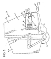
- the baler 10 is provided with ground wheels 12, a fore-and-aft extending tongue 14 adapted at its forwardmost end for attaching to a towing vehicle (not shown), pickup 16 for lifting windrowed crop material off the ground as the baler 10 advances over the ground, a baling chamber 18 defined by a series of endless, side-by-side belts 20 (only one belt depicted) trained about rollers 22 extending between a pair of spaced-apart, chamber defining sidewalls 24 (only one being shown).
- Tensioning rollers 26, 28 extend between respective arm pairs 30, 32 (only one arm of each pair is shown in the drawings) that are swingably attached to respective sidewalls 24 about aligned pivots 34, 36 (only one pivot of each arm pair being shown). Tensioning means (not shown) yieldably bias the arm pairs 30, 32 downwardly thereby keeping the belts 20 taut.
- a bale 38 is depicted in Fig. 2 formed in chamber 18, and having a longitudinal axis extending between the baler sidewalls 24.
- a dispensing tube 40 for applying twine to bale 38 is mounted forwardly of the bale 38 and has a twine receiving end 42 and a twine dispensing end 44.
- a strand of twine 46 is drawn from a supply roll 48 and pulled through dispensing tube 40 by the rotating bale.
- a twine monitor assembly 50 is in contact with the strand 46 intermediate the supply roll 48 and tube 40 for generating a pulsating signal in response to twine being dispensed.
- Assembly 50 includes a monitor wheel 52 rotativelyably mounted at its center on stub shaft 54 which extends from and is secured to frame element 58.
- the periphery of wheel 52 is defined by a V-shaped groove 60 which receives one wrap of strand 46.
- the V-shaped configuration prevents the wrap of strand 46 from sliding sideways off of the wheel periphery.
- a magnet 64 is affixed to a side of the wheel at a location radially outward from the central axis of rotation 54 of wheel 52 and during rotation of the wheel 52 follows a generally circular path of travel about axis 54.
- Assembly 50 further includes an electrical circuit 66 comprising a grounded terminal 68, a magnetically operated, normally biased open switch 72, an electrically actuated indicator light 74, a 12-volt battery 70, a second grounded terminal 76, and circuitry wire 78 interconnecting the aforementioned circuit components.
- the switch 72 is mounted on a frame piece 80 at a location adjacent the side of wheel 52 and adjacent the circular path of travel of the magnet 64 for closure thereby during each rotation of the wheel 52.
- the indicator light 74 is located in the cab of the towing vehicle (not shown) for easy viewing by the operator.
- twine tube 40 In use, the twine tube 40 is in its stand-by position outboard of sidewall 24 throughout the time the bale 38 is forming within the chamber 18. Once the bale 38 is fully formed, the dispensing end 44 of twine tube 40 is shifted from its standby position to a position adjacent the bale 38 and crop inlet 82. A portion of twine 84 dangles from the dispensing end 44 of tube 40 as depicted in Fig. 3.
- the dangling end of twine 84 will be caught up in new crop material delivered to the chamber 18 by the pickup 16. Wrapping of the bale will then commence as the rotating bale 38 pulls the twine 46 from the tube 40 while the dispensing end 44 of the tube 40 is moved along the length of the bale 38. As the strand 46 is pulled, it drives the wheel 52 through numerous rotations moving the magnet 64 through its circular path of travel, briefly bringing the magnet 64 closely adjacent to the switch 72, closing the switch 72 and completing the circuit 66 and energizing the light 74 for a brief period of time during each rotation.
- the light 74 will pulsate indicating to the operator that twine is being dispensed.
- the rate that the light 74 pulsates is directly related to the rate that twine is being dispensed (i.e., the faster the twine is dispensed, the faster the light will pulsate).
- twine 46 is thereby coiled helically around and along the length of the bale 38 as the dispensing end 44 of the tube 40 moves between the baler sidewalls 24 and along the length of the bale 38.
- the operator will observe the indicator light 74 to determine whether or not twine is being dispensed to the bale. During initiation of the wrapping operation, pulsating of the light 74 will indicate to the operator that the loose end 84 was picked up in the new crop material and imbedded therein.
- baler 10 will sever the strand 46 by means not shown, thereby forming a new loose end 84 and preventing the wrapped bale from pulling any additional twine from the twine supply 48. If no additional twine is being dispensed, a tensioner 86 gripping strand 46 intermediate wheel 52 and supply roll 48 gently resists the pulling of strand 46 therefrom, applying a braking force to wheel 52 and preventing the latter from free-wheeling following the wrapping.
- the path followed by the twine 46 from the supply roll 48 to the wheel 52 is determined by an eyelet 88 which is mounted above wheel 52 and which guides strand 46 onto the grooved periphery thereof, and by an eyelet 90 which is mounted above supply roll 48 for guiding twine therefrom to tensioner 86.
- the bale is discharged by raising rear baler portion 92 upwardly and rearwardly about the aligned pivots 94 (only one being shown) which interconnect the rear baler portion 92 with frame mounted, rigid, front baler portion 96.
- a compartment 98 is mounted on and extends outwardly from sidewall 24, and is divided into three subcompartments by partitions 100, one subcompartment containing the supply roll 48, and another subcompartment containing the wheel 52 and switch 72.
- the present invention contemplates eliminating the battery 70 from the circuit 66 and replacing the switch 72 with a copper coil having one end connected to a circuit wire leading from ground 68 and another end connect ed to a circuit wiring leading to light 74.
- This alternative arrangement also includes a plurality of spaced magnets 64 affixed to a side of the wheel 52 at equal distances radially outward from the central axis of rotation 54 of wheel 52. The magnets, during rotation of the wheel 52, follow a common circular path of travel about the axis 54.
- rotation of the wheel 52 brings successive magnets past the coil, causing the magnetic fields of the magnets 64 to pass through the coil thereby generating successivesive pulses of electrical current within the circuit and causing the light 74 to pulsate as the wheel rotates.
Landscapes
- Life Sciences & Earth Sciences (AREA)
- Environmental Sciences (AREA)
- Storage Of Harvested Produce (AREA)
Applications Claiming Priority (2)
| Application Number | Priority Date | Filing Date | Title |
|---|---|---|---|
| US10202687A | 1987-09-29 | 1987-09-29 | |
| US102026 | 1987-09-29 |
Publications (1)
| Publication Number | Publication Date |
|---|---|
| EP0309939A1 true EP0309939A1 (en) | 1989-04-05 |
Family
ID=22287721
Family Applications (1)
| Application Number | Title | Priority Date | Filing Date |
|---|---|---|---|
| EP88115668A Withdrawn EP0309939A1 (en) | 1987-09-29 | 1988-09-23 | Twine monitoring assembly for round balers |
Country Status (3)
| Country | Link |
|---|---|
| EP (1) | EP0309939A1 (da) |
| DK (1) | DK539788A (da) |
| PT (1) | PT88608A (da) |
Families Citing this family (1)
| Publication number | Priority date | Publication date | Assignee | Title |
|---|---|---|---|---|
| CN109168654B (zh) * | 2018-09-03 | 2021-06-22 | 真木农业设备(安徽)有限公司 | 一种农作物秸秆打捆机 |
Citations (3)
| Publication number | Priority date | Publication date | Assignee | Title |
|---|---|---|---|---|
| DE2038301A1 (de) * | 1970-08-01 | 1972-02-03 | Krupp Gmbh | Stillsetzvorrichtung fuer Verseilmaschinen |
| FR2341926A2 (fr) * | 1976-02-18 | 1977-09-16 | Lignes Telegraph Telephon | Dispositif de depart pour machine de cablerie |
| EP0181969A1 (en) * | 1984-11-21 | 1986-05-28 | Ford New Holland N.V. | Automatic twine wrapper for round bale forming machine |
-
1988
- 1988-09-23 EP EP88115668A patent/EP0309939A1/en not_active Withdrawn
- 1988-09-28 DK DK539788A patent/DK539788A/da not_active Application Discontinuation
- 1988-09-28 PT PT8860888A patent/PT88608A/pt not_active Application Discontinuation
Patent Citations (3)
| Publication number | Priority date | Publication date | Assignee | Title |
|---|---|---|---|---|
| DE2038301A1 (de) * | 1970-08-01 | 1972-02-03 | Krupp Gmbh | Stillsetzvorrichtung fuer Verseilmaschinen |
| FR2341926A2 (fr) * | 1976-02-18 | 1977-09-16 | Lignes Telegraph Telephon | Dispositif de depart pour machine de cablerie |
| EP0181969A1 (en) * | 1984-11-21 | 1986-05-28 | Ford New Holland N.V. | Automatic twine wrapper for round bale forming machine |
Also Published As
| Publication number | Publication date |
|---|---|
| DK539788A (da) | 1989-03-30 |
| PT88608A (pt) | 1989-07-31 |
| DK539788D0 (da) | 1988-09-28 |
Similar Documents
| Publication | Publication Date | Title |
|---|---|---|
| US4998961A (en) | Twine monitoring assembly for round balers | |
| US5568716A (en) | Round bale wrapping | |
| US4624179A (en) | Automatic control device for tying in a hay baler | |
| EP0252457B1 (en) | Machine for forming a cylindrical bale of crop | |
| US5216873A (en) | Wrapper cutoff mechanism for round balers | |
| US6981352B2 (en) | Round baler low net indication | |
| KR100935557B1 (ko) | 롤베일러 | |
| US4765235A (en) | Monitoring system for detecting malfunction of knotting mechanism on a crop baler | |
| US8671834B1 (en) | Twine tensioner arm position sensor arrangement | |
| CA1322695C (en) | Baling machine for forming cylindrical bales of crop | |
| US4248143A (en) | Interlacing twine wrapping mechanism for rotary balers | |
| US7918072B2 (en) | Mechanical net wrapper | |
| US4022120A (en) | Electrically powered twine wrapper for round bales | |
| GB2051670A (en) | Rotary baler having bale-ejecting apparatus | |
| EP0309939A1 (en) | Twine monitoring assembly for round balers | |
| EP0856248B1 (en) | Mistie detector system for agricultural balers. | |
| US5184545A (en) | Round baler twine wrapping apparatus | |
| US4269116A (en) | Apparatus for detecting malfunction in tying operation on a baler | |
| US5215005A (en) | Telescopic twine arm for round baler twine wrapping apparatus | |
| US4389929A (en) | Latching mechanism for a round baler | |
| US5215006A (en) | Twine clamp for round baler twine wrapping apparatus | |
| US6769353B1 (en) | Four twine tube round baler twine system | |
| US4094239A (en) | Apparatus for cutting hay baler twine | |
| US4440075A (en) | Round baler having wrapping twine cutter | |
| US4023479A (en) | Twine wrapper with spring supplement for round bales |
Legal Events
| Date | Code | Title | Description |
|---|---|---|---|
| PUAI | Public reference made under article 153(3) epc to a published international application that has entered the european phase |
Free format text: ORIGINAL CODE: 0009012 |
|
| AK | Designated contracting states |
Kind code of ref document: A1 Designated state(s): AT BE CH DE ES FR GB GR IT LI LU NL SE |
|
| 17P | Request for examination filed |
Effective date: 19890923 |
|
| RAP1 | Party data changed (applicant data changed or rights of an application transferred) |
Owner name: HESSTON BRAUD (SOCIETE ANONYME) |
|
| 17Q | First examination report despatched |
Effective date: 19891214 |
|
| STAA | Information on the status of an ep patent application or granted ep patent |
Free format text: STATUS: THE APPLICATION IS DEEMED TO BE WITHDRAWN |
|
| 18D | Application deemed to be withdrawn |
Effective date: 19900425 |