EP0309023A2 - Device for guiding and regulating the forward step in operating machines with intermittent forward motion, particularly automatic screen printing machines - Google Patents
Device for guiding and regulating the forward step in operating machines with intermittent forward motion, particularly automatic screen printing machines Download PDFInfo
- Publication number
- EP0309023A2 EP0309023A2 EP88201918A EP88201918A EP0309023A2 EP 0309023 A2 EP0309023 A2 EP 0309023A2 EP 88201918 A EP88201918 A EP 88201918A EP 88201918 A EP88201918 A EP 88201918A EP 0309023 A2 EP0309023 A2 EP 0309023A2
- Authority
- EP
- European Patent Office
- Prior art keywords
- sensor
- transducer
- machine
- sensors
- printing
- Prior art date
- Legal status (The legal status is an assumption and is not a legal conclusion. Google has not performed a legal analysis and makes no representation as to the accuracy of the status listed.)
- Withdrawn
Links
Images

Classifications
-
- B—PERFORMING OPERATIONS; TRANSPORTING
- B41—PRINTING; LINING MACHINES; TYPEWRITERS; STAMPS
- B41F—PRINTING MACHINES OR PRESSES
- B41F15/00—Screen printers
- B41F15/08—Machines
- B41F15/10—Machines for multicolour printing
-
- B—PERFORMING OPERATIONS; TRANSPORTING
- B41—PRINTING; LINING MACHINES; TYPEWRITERS; STAMPS
- B41F—PRINTING MACHINES OR PRESSES
- B41F13/00—Common details of rotary presses or machines
- B41F13/02—Conveying or guiding webs through presses or machines
- B41F13/04—Conveying or guiding webs through presses or machines intermittently
Definitions
- This invention relates to a device for the control and regulation of the intermittent forward motion of machine equipped with a closed loop conveyor belt or equivalent device, where the intermittent forward step must be extremely precise, particularly when the belt is very long, of the order of 80 m and more.
- Magnetic transducers provided with position readers are also known, but these employ a rigid length scale of not more than about 3 metres and, therefore, while they are very useful when applied to machine tools, they have no practical application on long belts or equivalent devices (large diameter rotary tables etc.).
- the present invention proposes a completely new system for the control of the intermittent forward motion which is extremely precise and reliable and has none of the negative features of the known systems.
- the invention consists of the application of a non-rigid magnetic position transducer to one of the edges of the conveyor belt, specifically, of a band of special flexible thermoplastic material which can be magnetised, said band being magnetised with alternating polarity at constant intervals.
- Two magnetic sensoring devices are mounted on the vertical axis of the band, a suitable distance apart, arranged one each side of the printing frame, or in a different position but always as close to the frame as possible, and are coupled to a step counting device, the step being constituted by the movement which has to be made, which in the case of the screen-printing machine corresponds to the exact nominal printing step.
- One of the two sensors is mounted on a bar whose length can be adjusted to adapt the machine to the various printing steps, the distance corresponding to the nominal step being used at that moment.
- the two sensors can communicate with one another, the first transmitting to the second the data it has monitored so that the second sensor can stop the belt in correspondance to the same lines of force recorded by the first sensor as the starting point, after a precise interval which corresponds to the exact distance between the two sensors.
- each section of the belt corresponding to a printing step in the case of screen-printing machines constitutes a discrete element and thus any errors due to the conditions of one section of the belt are not added to those of sub-sequent sections, therefore, the system operates as if it were controlled by the known rigid magnetic transducer monitoring system which however cannot be adapted to machines which are more than 2-3 metres long, while the system of this invention can be applied to belts of any length required, 80 metres or more.
- the aforesaid control unit made up of the magnetic transducer, the two sensors and the step counter, performs the function of reading and controlling the intermittent movement of the machine and is connected to another control and memory unit complete with man-machine interface of a basically known type.
- this unit memorises the exact position of each of the prints made, reproducing these positions perfectly on the next run so that the subsequent colours are superimposed in a way which is practically perfect because of the extremely high precision of the monitoring system which is capable of sensing the exact position of a point, since it can read the intensity of the field between two poles of the same name and also the direction of the lines of force.
- the automatic machine for screen-printing on fabric 1 is basically constituted by a conveyor belt 2 stretched between the motor rollers 3 and 4 driven by two D.C. motors 5 and 6.
- the fabric to be printed 7 is glued to this belt, indicated with the broken line in figure 1, thus for example an 80 m long machine can print pieces of fabric which are 160 m long.
- a known type of drying oven 8 is mounted, heated for example by a battery of infrared lamps 9.
- the automatic screen-printing device 10 is located on another section of the machine, preferably but not necessarily in the starting area. It is shown schematically in the drawings because its components are of a known type.
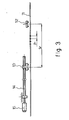
- a magnetic transducer tape 11 is applied to the whole length of one of the edges of the belt 2, as can be seen in fig. 3.
- This is constituted by a flexible tape of a suitable known magnetisable material, magnetised with alternating polarity according to an appropriate pre-set step P.
- Two magnetic sensors are fixed to the structure of the machine and arranged in a position above the vertical axis of the transducer tape 11.
- the first sensor 12 is in a fixed position and the second 13 is mounted so that it can slide on a rod 14 and thus can be moved in order to vary its distance from the first sensor 12 to adjust this distance to the various possible real printing steps Sr by means of a small motor 15.
- the rod 14 is of a length appropriate to cover all the possible widths of the screen-printing screens which are commonly used.
- a control unit and man-machine interface 16 of a basically known type is mounted, supplied with a keyboard and video screen, which memorises the data which are monitored and provides the commands to the working parts of the machine in accordance with the sequence of the operating cycle.
- the screen-printing device is located immediately after the sensors 12 and 13 of the device which controls the forward step of the machine, but according to the invention it can also be located either before or between the two sensors 12 and13.
- the device operates in the following way.
- the precise distance between the two sensors 12 and 13 corresponding to the desired printing step Sr is defined - adjustable within a given range according to the design - and the machine is started up and the operating cycle commences with the following operations.
- Sensor 13 receives the signal sent to it by the transducer which is in axis beneath it at that moment and transmits the information to sensor 12.
- the control unit 16 gives consent for the forward movement of the belt and motors 5 and 6 come into action, moving the belt in the direction shown by the arrow.
- sensor 12 intercepts exactly the same signal as the one previously read by sensor 13, it transmits a signal to the control unit 16 which stops the motors and thus the belt 2 stops in a front of sensor 12 in precisely the same position as it was found to be in front of sensor 13.
- the screen-printing device comes into action and prints the first screen and a first operating cycle has than terminated.
- sensor 13 reads the signal from the transducer located beneath it and transmits it to sensor 12 via the control unit 16.
- the control unit 16 gives the command for the forward movement of the belt 2 and stops the belt when sensor 12 intercepts beneath it the same signal as that read and transmitted to it by sensor 13.
- the screen-printing device then proceeds to print the second screen and so on. With this system sections of the conveyor belt 2, and thus of the fabric 7 to be printed, of a width Sr measured for each specific section of the belt are disposed under the screen-printing device.
- All the data relating to the various subsequent printings are recorded by the control unit 16 for the whole length of the belt and thus, in the case of printing with several colours, the data are taken and repeated exactly as they were in the first run as many times as are required to print the colours of which the design is composed.
- each specific element of the printing step Sr of the belt which has already been printed is re-presented for printing the next colour in precisely the same position under the screen-printing device as it was when the first colour was printed, thus obtaining a superimposition and alignment which are perfect in practice.
- the flexible strip of thermoplastic material which can be magnetised can be inserted in the belt instead of being produced separately and applied to the belt, or it can be manufactured at the same time as the belt incorporating a side strip composed of thermoplastic material or magnetisable rubber.
Abstract
This invention relates to a device for the control and regulation of the intermittent forward step of a machine equipped with a closed loop conveyor belt, or similar device, where the intermittent forward step must be highly precise, in particular when the belt is very long, even 80 m or more, said device having a primary specific application on machines for automatic screen-printing for which it was first produced.
It consists of the fact that a flexible magnetic transducer (11) is applied along the whole length of one of the edges of the conveyor belt (2), magnetised with alternating polarity at a constant step P, with which two magnetic sensors (12-13) interact, said sensors being positioned above the transducer (11) at an appropriate pre-set distance apart, equal to the real printing step Sr and in correspondance to the vertical axis of the transducer (11), the sensors (12-13) being connected to a step counter and being capable of communicating with one another via a control unit (16), of a basically known design, so that the signal received by the sensor (13) and emitted from the point of the transducer (11), which at a given point of the operating cycle is located beneath the sensor (13), is sent by sensor (13) to sensor (12), which will cause the machine to stop beneath it only when it has read an identical signal, the machine stopping in correspondance to the same exact point of the transducer (11) and therefore of the conveyor belt (2) which was previously located beneath the sensor (13).
The distance Sr between the two sensors (12) and (13) can be varied since one of the sensors, for example sensor (13), is mobilely mounted on a rod (14) fixed to the machine and can run longitudinally along the rod (14) actuateed by a small motor (15) and thus vary its distance from the sensor (12).
Description
- This invention relates to a device for the control and regulation of the intermittent forward motion of machine equipped with a closed loop conveyor belt or equivalent device, where the intermittent forward step must be extremely precise, particularly when the belt is very long, of the order of 80 m and more.
- The primary specific application of this device is for automatic screen-printing machines for which it was first created, but it can also be applied in all those cases and to all those intermittent forward motion machines of considerable length in which extreme step precision is required and in which this precision must not be compromised by the increment of errors caused by the length of the machine and the functioning conditions of the machine.
- In the screen-printing field certain types of automatic screen-printing machines are already known, i.e. those with a closed loop belt and the rotary tables.
- When the screen-printing system has to be used to print panels on pieces of fabric glued to long conveyor belts, or pre-cut garments or other articles where extreme precision is necessary, both between one print and the next in the case of a consecutive repetitive design and in the superimposition of colours in the case of a multi-colour design, then the devices which control the advance of the means (conveyor belt, table etc.) on which the products are supported, generally fabric to be printed, became of the greatest importance.
- Up to now many systems have been adopted such as providing holes in the mat of the conveyor belt to be matched up with pins of a wheel with an incorporated encoder, or the more efficient system of printing markings on the substratum of the conveyor belt before the first colour is printed, repeating the process for each color, together with means which intercept these markings and control the intermittent forward motion of the conveyor belt (see EP-A2- 0130751).
- However, this system requires a marking printer on the edge of the support web of the piece to be printed each time and therefore the markings must also be cancelled as the length of the design varies.
- Magnetic transducers provided with position readers are also known, but these employ a rigid length scale of not more than about 3 metres and, therefore, while they are very useful when applied to machine tools, they have no practical application on long belts or equivalent devices (large diameter rotary tables etc.).
- The present invention proposes a completely new system for the control of the intermittent forward motion which is extremely precise and reliable and has none of the negative features of the known systems.
- The invention consists of the application of a non-rigid magnetic position transducer to one of the edges of the conveyor belt, specifically, of a band of special flexible thermoplastic material which can be magnetised, said band being magnetised with alternating polarity at constant intervals. Two magnetic sensoring devices are mounted on the vertical axis of the band, a suitable distance apart, arranged one each side of the printing frame, or in a different position but always as close to the frame as possible, and are coupled to a step counting device, the step being constituted by the movement which has to be made, which in the case of the screen-printing machine corresponds to the exact nominal printing step. One of the two sensors is mounted on a bar whose length can be adjusted to adapt the machine to the various printing steps, the distance corresponding to the nominal step being used at that moment. The two sensors can communicate with one another, the first transmitting to the second the data it has monitored so that the second sensor can stop the belt in correspondance to the same lines of force recorded by the first sensor as the starting point, after a precise interval which corresponds to the exact distance between the two sensors.
- With this double magnetic sensor system, in which the second receives from the first exact information on the precise point monitored by the first sensor, each section of the belt corresponding to a printing step in the case of screen-printing machines constitutes a discrete element and thus any errors due to the conditions of one section of the belt are not added to those of sub-sequent sections, therefore, the system operates as if it were controlled by the known rigid magnetic transducer monitoring system which however cannot be adapted to machines which are more than 2-3 metres long, while the system of this invention can be applied to belts of any length required, 80 metres or more.
- The aforesaid control unit, made up of the magnetic transducer, the two sensors and the step counter, performs the function of reading and controlling the intermittent movement of the machine and is connected to another control and memory unit complete with man-machine interface of a basically known type. During the first run of the belt, this unit memorises the exact position of each of the prints made, reproducing these positions perfectly on the next run so that the subsequent colours are superimposed in a way which is practically perfect because of the extremely high precision of the monitoring system which is capable of sensing the exact position of a point, since it can read the intensity of the field between two poles of the same name and also the direction of the lines of force.
- This invention will be more clearly understood from the description of the embodiment given here as a non-limiting example applied to a closed loop screen-printing machine. Once again it is emphasised that it can be applied to other types of screen-printing machines such as rotary tables, screen-printing machines for pre-cut fabrics and all machines having a particular length and operating on flexible supports, to which the known system of the monitoring by a rigid magnetic bar cannot be applied.
- The example embodiment is illustrated in the attached drawings where:
- Fig. 1 shows a schematic plan view of a machine for screen-printing fabric on a conveyor belt;
- Figure 2 is a side view of figure 1;
- Figure 3 shows a detail of the transducer and monitoring device according to this invention.
- Referring now to figures 1, 2 and 3, the automatic machine for screen-printing on fabric 1 is basically constituted by a
conveyor belt 2 stretched between the motor rollers 3 and 4 driven by two D.C. motors 5 and 6. - The fabric to be printed 7 is glued to this belt, indicated with the broken line in figure 1, thus for example an 80 m long machine can print pieces of fabric which are 160 m long.
- The direction of rotation of the belt is shown by an arrow in figure 1.
- At the final upper end of the belt in the direction of rotation, a known type of drying oven 8 is mounted, heated for example by a battery of infrared lamps 9.
- The automatic screen-
printing device 10 is located on another section of the machine, preferably but not necessarily in the starting area. It is shown schematically in the drawings because its components are of a known type. - A magnetic transducer tape 11 is applied to the whole length of one of the edges of the
belt 2, as can be seen in fig. 3. This is constituted by a flexible tape of a suitable known magnetisable material, magnetised with alternating polarity according to an appropriate pre-set step P. - Two magnetic sensors are fixed to the structure of the machine and arranged in a position above the vertical axis of the transducer tape 11. The
first sensor 12 is in a fixed position and the second 13 is mounted so that it can slide on arod 14 and thus can be moved in order to vary its distance from thefirst sensor 12 to adjust this distance to the various possible real printing steps Sr by means of asmall motor 15. Therod 14 is of a length appropriate to cover all the possible widths of the screen-printing screens which are commonly used. - On the other side of the machine, the operator side, a control unit and man-
machine interface 16 of a basically known type is mounted, supplied with a keyboard and video screen, which memorises the data which are monitored and provides the commands to the working parts of the machine in accordance with the sequence of the operating cycle. - For construction reasons, in figures 1 and 2 the screen-printing device is located immediately after the
sensors sensors 12 and13. - The device operates in the following way.
- The precise distance between the two
sensors Sensor 13 receives the signal sent to it by the transducer which is in axis beneath it at that moment and transmits the information tosensor 12. Thecontrol unit 16 gives consent for the forward movement of the belt and motors 5 and 6 come into action, moving the belt in the direction shown by the arrow. Whensensor 12 intercepts exactly the same signal as the one previously read bysensor 13, it transmits a signal to thecontrol unit 16 which stops the motors and thus thebelt 2 stops in a front ofsensor 12 in precisely the same position as it was found to be in front ofsensor 13. The screen-printing device comes into action and prints the first screen and a first operating cycle has than terminated. - Once again,
sensor 13 reads the signal from the transducer located beneath it and transmits it tosensor 12 via thecontrol unit 16. Thecontrol unit 16 gives the command for the forward movement of thebelt 2 and stops the belt whensensor 12 intercepts beneath it the same signal as that read and transmitted to it bysensor 13. The screen-printing device then proceeds to print the second screen and so on. With this system sections of theconveyor belt 2, and thus of the fabric 7 to be printed, of a width Sr measured for each specific section of the belt are disposed under the screen-printing device. - Obviously, as in the known machines, there is acceleration when the belt starts and deceleration before the belt stops, but these are design details which have nothing to do with the essence of this patent.
- It must be remembered that the resolution of such an apparatus, i.e. the smallest amount of movement which it can detect, is 4 thousandths of a millimetre. Therefore, taking into account other components of the machine such as mass inertia, belt tension etc., it is possible to print with an accuracy of lower than one tenth of a millimetre both in sequence and in superimposition, a level of accuracy which has never been previously achieved with machines of this type.
- All the data relating to the various subsequent printings are recorded by the
control unit 16 for the whole length of the belt and thus, in the case of printing with several colours, the data are taken and repeated exactly as they were in the first run as many times as are required to print the colours of which the design is composed. - Therefore, each specific element of the printing step Sr of the belt which has already been printed is re-presented for printing the next colour in precisely the same position under the screen-printing device as it was when the first colour was printed, thus obtaining a superimposition and alignment which are perfect in practice.
- The embodiment described here has been provided purely as a non-limiting example and other different embodiments can be implemented while still remaining with the scope of this patent.
- For example, the flexible strip of thermoplastic material which can be magnetised can be inserted in the belt instead of being produced separately and applied to the belt, or it can be manufactured at the same time as the belt incorporating a side strip composed of thermoplastic material or magnetisable rubber.
Claims (4)
1. Device for guiding and regulating the forward step of operating machines with intermittent forward motion, in particular automatic screen-printing machines, characterised by the fact that a flexible magnetic transducer, magnetised with alternating polarity at a constant step (P) is applied to or inserted into one of the edges of the conveyor belt (2) or incorporated in it during manufacture, and that two magnetic sensors (12-13) positioned above the transducer (11) an appropriate pre-set distance apart in correspondance to the vertical axis of the transducer (11) interact with it, said sensors (12-13) being connected to a step counter and being able to communicate with one another via a control unit (16) of a basically known design, so that the signal received by the sensor (13) and emitted by the transducer (11), which at a given moment of the operating cycle is located beneath the sensor (13), is sent by the sensor (13) to the sensor (12), whereby only when an identical signal has been read, the machine stops in correspondance to the same exact point of the transducer (11) and therefore of the belt (2) which was previously located beneath the sensor (13).
2. Device according to claim 1, characterised by the fact that the non-rigid transducer is consituted by a strip of a special magnetisable thermoplastic material of a known type.
3. Device according to claim 1, characterised by the fact that the appropriate pre-set distance between the sensors (12) and (13) corresponds to the real printing step of the printing screen being used on the machine at the time.
4. Device according to claim 3, characterised by the fact that in order to be able to vary the operating distance Sr between the two sensors (12) and (13), sensor (12) is attached to a fixed point of the machine while sensor (13) is mobilely mounted on a rod (14) fixed to the machine and can run longitudinally along the rod (14), actuated by a small motor (15), and thus can vary its distance from the sensor (12) in order to adapt the distance to the real printing step Sr of the screen mounted at that moment on the machine.
Applications Claiming Priority (2)
| Application Number | Priority Date | Filing Date | Title |
|---|---|---|---|
| IT22034/87A IT1222737B (en) | 1987-09-25 | 1987-09-25 | GUIDE DEVICE AND ADJUSTMENT OF THE FORWARD STEP IN INTERMITTENT OPERATING MACHINES, IN PARTICULAR IN AUTOMATIC SCREEN PRINTING MACHINES |
| IT2203487 | 1987-09-25 |
Publications (2)
| Publication Number | Publication Date |
|---|---|
| EP0309023A2 true EP0309023A2 (en) | 1989-03-29 |
| EP0309023A3 EP0309023A3 (en) | 1990-04-11 |
Family
ID=11190490
Family Applications (1)
| Application Number | Title | Priority Date | Filing Date |
|---|---|---|---|
| EP88201918A Withdrawn EP0309023A3 (en) | 1987-09-25 | 1988-09-07 | Device for guiding and regulating the forward step in operating machines with intermittent forward motion, particularly automatic screen printing machines |
Country Status (2)
| Country | Link |
|---|---|
| EP (1) | EP0309023A3 (en) |
| IT (1) | IT1222737B (en) |
Cited By (4)
| Publication number | Priority date | Publication date | Assignee | Title |
|---|---|---|---|---|
| EP0782921A1 (en) * | 1995-12-19 | 1997-07-09 | Viero S.R.L. | Rotary-belt printing machine comprising a positioning device with linear optical sensor |
| EP0782922A1 (en) * | 1995-12-19 | 1997-07-09 | Viero S.R.L. | Roller-printing rotary belt machine synchronization method and machine in accordance with this method |
| ES2160034A1 (en) * | 1998-02-17 | 2001-10-16 | Francesco Schinco | Screen printing machine for tiles. |
| CN110802936A (en) * | 2019-12-11 | 2020-02-18 | 浙江宝石蝶围巾有限公司 | Silk scarf bedplate printing method |
Citations (4)
| Publication number | Priority date | Publication date | Assignee | Title |
|---|---|---|---|---|
| GB959972A (en) * | 1961-09-27 | 1964-06-03 | Heberlein & Co Ag | Screen-printing apparatus |
| GB1082881A (en) * | 1965-03-08 | 1967-09-13 | Keuffel & Esser Co | Magnetic tape position measuring device |
| JPS59132010A (en) * | 1983-01-17 | 1984-07-30 | Hitachi Ltd | Positioning method of continuous sheet-shaped work |
| EP0130751A2 (en) * | 1983-06-24 | 1985-01-09 | Toshin Kogyo Co. Ltd. | Continuous multicolor printing method and apparatus |
-
1987
- 1987-09-25 IT IT22034/87A patent/IT1222737B/en active
-
1988
- 1988-09-07 EP EP88201918A patent/EP0309023A3/en not_active Withdrawn
Patent Citations (4)
| Publication number | Priority date | Publication date | Assignee | Title |
|---|---|---|---|---|
| GB959972A (en) * | 1961-09-27 | 1964-06-03 | Heberlein & Co Ag | Screen-printing apparatus |
| GB1082881A (en) * | 1965-03-08 | 1967-09-13 | Keuffel & Esser Co | Magnetic tape position measuring device |
| JPS59132010A (en) * | 1983-01-17 | 1984-07-30 | Hitachi Ltd | Positioning method of continuous sheet-shaped work |
| EP0130751A2 (en) * | 1983-06-24 | 1985-01-09 | Toshin Kogyo Co. Ltd. | Continuous multicolor printing method and apparatus |
Non-Patent Citations (1)
| Title |
|---|
| PATENT ABSTRACTS OF JAPAN vol. 8, no. 259 (P-317)(1696) 28 November 1984, & JP-A-59 132010 (HITACHI SEISAKUSHO K.K.) 30 July 1984, * |
Cited By (4)
| Publication number | Priority date | Publication date | Assignee | Title |
|---|---|---|---|---|
| EP0782921A1 (en) * | 1995-12-19 | 1997-07-09 | Viero S.R.L. | Rotary-belt printing machine comprising a positioning device with linear optical sensor |
| EP0782922A1 (en) * | 1995-12-19 | 1997-07-09 | Viero S.R.L. | Roller-printing rotary belt machine synchronization method and machine in accordance with this method |
| ES2160034A1 (en) * | 1998-02-17 | 2001-10-16 | Francesco Schinco | Screen printing machine for tiles. |
| CN110802936A (en) * | 2019-12-11 | 2020-02-18 | 浙江宝石蝶围巾有限公司 | Silk scarf bedplate printing method |
Also Published As
| Publication number | Publication date |
|---|---|
| IT1222737B (en) | 1990-09-12 |
| EP0309023A3 (en) | 1990-04-11 |
| IT8722034A0 (en) | 1987-09-25 |
Similar Documents
| Publication | Publication Date | Title |
|---|---|---|
| US5255598A (en) | Screen printing device with continuous registering of rotating stencils | |
| US5313886A (en) | Electronic method of positioning a register mark sensor of a sheet printing machine | |
| CA1093660A (en) | Gate control for printed web scanner | |
| US4007866A (en) | Web transport arrangement | |
| US4557372A (en) | Belt system with alignment apparatus | |
| US4391190A (en) | Pre-setting of printing machines | |
| US3713571A (en) | Method and apparatus for feeding strip material | |
| JPS6114896A (en) | Mold cutting press for web material | |
| US4984458A (en) | System for measuring the relaxed length of a moving web | |
| US5777878A (en) | Screen printing press having longitudinal, lateral and angular screen frame registration system and method | |
| US5968303A (en) | Method and apparatus for sticking a label | |
| US5252838A (en) | Optical device provides a correct alignment for printing screen with reflective markers and orientation sensors | |
| EP0309023A2 (en) | Device for guiding and regulating the forward step in operating machines with intermittent forward motion, particularly automatic screen printing machines | |
| US4878773A (en) | Ribbon feed control apparatus and method | |
| US5706722A (en) | Process for controlling a cylinder-type silk screen printing machine | |
| CA1065688A (en) | Automatic stitching pattern control system and method for a sewing machine | |
| CA1116724A (en) | Printer system ribbon drive having constant ribbon speed and tension | |
| US4947685A (en) | System for measuring the repeat length of a moving web | |
| EP0446977B1 (en) | Device for guiding and regulating the forward step in operating machines with intermittent forward motion, particularly for automatic screen printing machines | |
| JP2632304B2 (en) | Register presetting device | |
| US4200049A (en) | Method for automatic stitching | |
| EP0727315A2 (en) | Letter printing method for a packaging machine | |
| EP0687560A1 (en) | High-precision printing machine, particularly for fabrics or the like, with multiple printing stations | |
| US4147440A (en) | Sliding code disc reader and detent therefor for dual pitch web feeding | |
| JPS59207251A (en) | Positioning method of sensor for detecting register mark in offset rotary press |
Legal Events
| Date | Code | Title | Description |
|---|---|---|---|
| PUAI | Public reference made under article 153(3) epc to a published international application that has entered the european phase |
Free format text: ORIGINAL CODE: 0009012 |
|
| AK | Designated contracting states |
Kind code of ref document: A2 Designated state(s): AT BE CH DE ES FR GB GR IT LI LU NL SE |
|
| PUAL | Search report despatched |
Free format text: ORIGINAL CODE: 0009013 |
|
| AK | Designated contracting states |
Kind code of ref document: A3 Designated state(s): AT BE CH DE ES FR GB GR IT LI LU NL SE |
|
| 17P | Request for examination filed |
Effective date: 19900514 |
|
| STAA | Information on the status of an ep patent application or granted ep patent |
Free format text: STATUS: THE APPLICATION IS DEEMED TO BE WITHDRAWN |
|
| 18D | Application deemed to be withdrawn |
Effective date: 19920401 |