EP0308483B1 - Magneto-resistive thin film head for digital magnetic storage device - Google Patents
Magneto-resistive thin film head for digital magnetic storage device Download PDFInfo
- Publication number
- EP0308483B1 EP0308483B1 EP88903602A EP88903602A EP0308483B1 EP 0308483 B1 EP0308483 B1 EP 0308483B1 EP 88903602 A EP88903602 A EP 88903602A EP 88903602 A EP88903602 A EP 88903602A EP 0308483 B1 EP0308483 B1 EP 0308483B1
- Authority
- EP
- European Patent Office
- Prior art keywords
- strip
- magneto
- head
- magnetic
- resistive
- Prior art date
- Legal status (The legal status is an assumption and is not a legal conclusion. Google has not performed a legal analysis and makes no representation as to the accuracy of the status listed.)
- Expired - Lifetime
Links
- 238000003860 storage Methods 0.000 title claims abstract description 10
- 239000010409 thin film Substances 0.000 title description 6
- 230000004907 flux Effects 0.000 claims abstract description 92
- 239000000463 material Substances 0.000 claims abstract description 10
- 238000012545 processing Methods 0.000 claims abstract description 6
- 230000004044 response Effects 0.000 claims abstract description 6
- 230000005381 magnetic domain Effects 0.000 claims description 11
- 230000005330 Barkhausen effect Effects 0.000 claims description 10
- 230000000694 effects Effects 0.000 claims description 10
- 230000005415 magnetization Effects 0.000 claims description 6
- 230000001154 acute effect Effects 0.000 claims description 4
- 238000009987 spinning Methods 0.000 abstract description 4
- 230000008859 change Effects 0.000 description 7
- 230000035945 sensitivity Effects 0.000 description 7
- 239000000696 magnetic material Substances 0.000 description 5
- 230000007704 transition Effects 0.000 description 5
- 239000012466 permeate Substances 0.000 description 4
- 229910001030 Iron–nickel alloy Inorganic materials 0.000 description 3
- 230000015572 biosynthetic process Effects 0.000 description 3
- 238000000926 separation method Methods 0.000 description 3
- VYPSYNLAJGMNEJ-UHFFFAOYSA-N Silicium dioxide Chemical compound O=[Si]=O VYPSYNLAJGMNEJ-UHFFFAOYSA-N 0.000 description 2
- 238000013500 data storage Methods 0.000 description 2
- 230000004048 modification Effects 0.000 description 2
- 238000012986 modification Methods 0.000 description 2
- 229910000889 permalloy Inorganic materials 0.000 description 2
- 101100313377 Caenorhabditis elegans stip-1 gene Proteins 0.000 description 1
- 101100313382 Dictyostelium discoideum stip-2 gene Proteins 0.000 description 1
- 101100516335 Rattus norvegicus Necab1 gene Proteins 0.000 description 1
- 101150059016 TFIP11 gene Proteins 0.000 description 1
- 229910045601 alloy Inorganic materials 0.000 description 1
- 239000000956 alloy Substances 0.000 description 1
- PNEYBMLMFCGWSK-UHFFFAOYSA-N aluminium oxide Inorganic materials [O-2].[O-2].[O-2].[Al+3].[Al+3] PNEYBMLMFCGWSK-UHFFFAOYSA-N 0.000 description 1
- 239000012141 concentrate Substances 0.000 description 1
- 230000001143 conditioned effect Effects 0.000 description 1
- 238000007796 conventional method Methods 0.000 description 1
- 238000011161 development Methods 0.000 description 1
- 230000002708 enhancing effect Effects 0.000 description 1
- 238000009413 insulation Methods 0.000 description 1
- 239000012212 insulator Substances 0.000 description 1
- 230000002452 interceptive effect Effects 0.000 description 1
- 238000012886 linear function Methods 0.000 description 1
- 238000004519 manufacturing process Methods 0.000 description 1
- 238000000034 method Methods 0.000 description 1
- 229920002120 photoresistant polymer Polymers 0.000 description 1
- 229920006395 saturated elastomer Polymers 0.000 description 1
- 239000004065 semiconductor Substances 0.000 description 1
- 235000012239 silicon dioxide Nutrition 0.000 description 1
- 239000000377 silicon dioxide Substances 0.000 description 1
- 230000007480 spreading Effects 0.000 description 1
- 238000003892 spreading Methods 0.000 description 1
Images


Classifications
-
- G—PHYSICS
- G11—INFORMATION STORAGE
- G11B—INFORMATION STORAGE BASED ON RELATIVE MOVEMENT BETWEEN RECORD CARRIER AND TRANSDUCER
- G11B5/00—Recording by magnetisation or demagnetisation of a record carrier; Reproducing by magnetic means; Record carriers therefor
- G11B5/127—Structure or manufacture of heads, e.g. inductive
- G11B5/33—Structure or manufacture of flux-sensitive heads, i.e. for reproduction only; Combination of such heads with means for recording or erasing only
- G11B5/39—Structure or manufacture of flux-sensitive heads, i.e. for reproduction only; Combination of such heads with means for recording or erasing only using magneto-resistive devices or effects
-
- G—PHYSICS
- G11—INFORMATION STORAGE
- G11B—INFORMATION STORAGE BASED ON RELATIVE MOVEMENT BETWEEN RECORD CARRIER AND TRANSDUCER
- G11B5/00—Recording by magnetisation or demagnetisation of a record carrier; Reproducing by magnetic means; Record carriers therefor
- G11B5/127—Structure or manufacture of heads, e.g. inductive
- G11B5/33—Structure or manufacture of flux-sensitive heads, i.e. for reproduction only; Combination of such heads with means for recording or erasing only
- G11B5/39—Structure or manufacture of flux-sensitive heads, i.e. for reproduction only; Combination of such heads with means for recording or erasing only using magneto-resistive devices or effects
- G11B5/3903—Structure or manufacture of flux-sensitive heads, i.e. for reproduction only; Combination of such heads with means for recording or erasing only using magneto-resistive devices or effects using magnetic thin film layers or their effects, the films being part of integrated structures
- G11B5/3906—Details related to the use of magnetic thin film layers or to their effects
- G11B5/3916—Arrangements in which the active read-out elements are coupled to the magnetic flux of the track by at least one magnetic thin film flux guide
- G11B5/3919—Arrangements in which the active read-out elements are coupled to the magnetic flux of the track by at least one magnetic thin film flux guide the guide being interposed in the flux path
- G11B5/3922—Arrangements in which the active read-out elements are coupled to the magnetic flux of the track by at least one magnetic thin film flux guide the guide being interposed in the flux path the read-out elements being disposed in magnetic shunt relative to at least two parts of the flux guide structure
- G11B5/3925—Arrangements in which the active read-out elements are coupled to the magnetic flux of the track by at least one magnetic thin film flux guide the guide being interposed in the flux path the read-out elements being disposed in magnetic shunt relative to at least two parts of the flux guide structure the two parts being thin films
-
- G—PHYSICS
- G11—INFORMATION STORAGE
- G11B—INFORMATION STORAGE BASED ON RELATIVE MOVEMENT BETWEEN RECORD CARRIER AND TRANSDUCER
- G11B5/00—Recording by magnetisation or demagnetisation of a record carrier; Reproducing by magnetic means; Record carriers therefor
- G11B5/127—Structure or manufacture of heads, e.g. inductive
- G11B5/33—Structure or manufacture of flux-sensitive heads, i.e. for reproduction only; Combination of such heads with means for recording or erasing only
- G11B5/39—Structure or manufacture of flux-sensitive heads, i.e. for reproduction only; Combination of such heads with means for recording or erasing only using magneto-resistive devices or effects
- G11B5/3903—Structure or manufacture of flux-sensitive heads, i.e. for reproduction only; Combination of such heads with means for recording or erasing only using magneto-resistive devices or effects using magnetic thin film layers or their effects, the films being part of integrated structures
-
- G—PHYSICS
- G11—INFORMATION STORAGE
- G11B—INFORMATION STORAGE BASED ON RELATIVE MOVEMENT BETWEEN RECORD CARRIER AND TRANSDUCER
- G11B5/00—Recording by magnetisation or demagnetisation of a record carrier; Reproducing by magnetic means; Record carriers therefor
- G11B5/127—Structure or manufacture of heads, e.g. inductive
- G11B5/33—Structure or manufacture of flux-sensitive heads, i.e. for reproduction only; Combination of such heads with means for recording or erasing only
- G11B5/39—Structure or manufacture of flux-sensitive heads, i.e. for reproduction only; Combination of such heads with means for recording or erasing only using magneto-resistive devices or effects
- G11B5/3903—Structure or manufacture of flux-sensitive heads, i.e. for reproduction only; Combination of such heads with means for recording or erasing only using magneto-resistive devices or effects using magnetic thin film layers or their effects, the films being part of integrated structures
- G11B5/3906—Details related to the use of magnetic thin film layers or to their effects
- G11B5/3945—Heads comprising more than one sensitive element
- G11B5/3948—Heads comprising more than one sensitive element the sensitive elements being active read-out elements
- G11B5/3951—Heads comprising more than one sensitive element the sensitive elements being active read-out elements the active elements being arranged on several parallel planes
- G11B5/3954—Heads comprising more than one sensitive element the sensitive elements being active read-out elements the active elements being arranged on several parallel planes the active elements transducing on a single track
-
- G—PHYSICS
- G11—INFORMATION STORAGE
- G11B—INFORMATION STORAGE BASED ON RELATIVE MOVEMENT BETWEEN RECORD CARRIER AND TRANSDUCER
- G11B5/00—Recording by magnetisation or demagnetisation of a record carrier; Reproducing by magnetic means; Record carriers therefor
- G11B5/127—Structure or manufacture of heads, e.g. inductive
- G11B5/33—Structure or manufacture of flux-sensitive heads, i.e. for reproduction only; Combination of such heads with means for recording or erasing only
- G11B5/39—Structure or manufacture of flux-sensitive heads, i.e. for reproduction only; Combination of such heads with means for recording or erasing only using magneto-resistive devices or effects
- G11B5/3903—Structure or manufacture of flux-sensitive heads, i.e. for reproduction only; Combination of such heads with means for recording or erasing only using magneto-resistive devices or effects using magnetic thin film layers or their effects, the films being part of integrated structures
- G11B5/398—Specially shaped layers
-
- G—PHYSICS
- G11—INFORMATION STORAGE
- G11B—INFORMATION STORAGE BASED ON RELATIVE MOVEMENT BETWEEN RECORD CARRIER AND TRANSDUCER
- G11B5/00—Recording by magnetisation or demagnetisation of a record carrier; Reproducing by magnetic means; Record carriers therefor
- G11B2005/0002—Special dispositions or recording techniques
- G11B2005/0005—Arrangements, methods or circuits
- G11B2005/0008—Magnetic conditionning of heads, e.g. biasing
-
- G—PHYSICS
- G11—INFORMATION STORAGE
- G11B—INFORMATION STORAGE BASED ON RELATIVE MOVEMENT BETWEEN RECORD CARRIER AND TRANSDUCER
- G11B5/00—Recording by magnetisation or demagnetisation of a record carrier; Reproducing by magnetic means; Record carriers therefor
- G11B5/02—Recording, reproducing, or erasing methods; Read, write or erase circuits therefor
- G11B5/09—Digital recording
-
- G—PHYSICS
- G11—INFORMATION STORAGE
- G11B—INFORMATION STORAGE BASED ON RELATIVE MOVEMENT BETWEEN RECORD CARRIER AND TRANSDUCER
- G11B5/00—Recording by magnetisation or demagnetisation of a record carrier; Reproducing by magnetic means; Record carriers therefor
- G11B5/10—Structure or manufacture of housings or shields for heads
- G11B5/11—Shielding of head against electric or magnetic fields
Definitions
- the invention relates generally to the field of magentic data storage devices, and particularly to read/write heads for use in such devices.
- the invention particularly provides a new magneto-resistive thin film head for use in disk data storage devices for use in digital data processing systems.
- a typical modern digital data processing system comprises a hierarchy of memory devices, including a semiconductor main memory of relatively small capacity, and one or more mass storage devices, which have a much greater capacity than the main memory, but which are also relatively much slower.
- the mass storage devices provide a back-up store for data which is in the main memory, and also for the voluminous amounts of data which will not fit into the main memory, but which can be called upon by the processor when it is needed.
- a processor typically only obtains information directly from the main memory, and so, when it needs information which at the moment is only in a mass storage device, it enables the mass storage device to copy the information into the main memory. Some time later, after it has processed the information, the processor enables the processed information to be stored in the mass storage device. This frees up storage in the main memory so that other information may be stored there.
- Typical mass storage devices store information on spinning magnetic disks, the information being recorded in the form of transitions in magnetic flux on the magnetic surface of the disk.
- the data is recorded in a plurarlity of tracks, with each track being a selected radial distance from the center of the disk.
- a read/write head flies in close proximity to the disk surface and is held in the appropriate radial position over the disk by an arm. Under the control of the system's processor unit the arm can move the read/write head to the appropriate track in which the data is recorded so that it may be read, or into which the data is to be written.
- a read/write head comprises two pole pieces formed from a magnetic material and a wire coil. At one end, the pole pieces are touching and at the other end there is a slight gap between the pole pieces. The head is positioned so that the gap is directed towards the disk surface. When electric current is impressed on the coil, a magentic flux is generated, which is impressed upon the pole pieces. At the gap, the magnetic flux is directed through the magnetic material in the adjacent disk surface to thereby impress magnetic flux therein.
- the coil is energized with a varying voltage pattern which corresponds to the data to be written.
- the varying voltage results in the generation of a corresponding pattern in the magnetic flux which the head applies to the surface of the rotating disk. Since the disk moves relative to the head, the magnetic flux on the disk surface also varies along the length of the arc traversed by the head on the disk.
- the head When the data is read, the head flies over the arc of the disk surface in which the data was written. A small amount of flux from the disk permeates the head. Tne flux in the head varies in response to the pattern of flux recorded on the disk. The varying flux results in the generation of a varying voltage in the coil, which, in turn, is sensed as the previously-recorded data.
- read/write heads which include a strip of magneto-resistive material, such as a nickel iron alloy.
- a nickel iron alloy is commercially known as "Permalloy”.
- the strip is positioned in the gap between the pole pieces that are adjacent the disk.
- the electrical resistance of the magneto-resisitive material is related to an applied magnetic field.
- the resistance of the magneto-resistive material varies in response to the variations in the flux in the head, which in turn reflects the variations in the flux on the disk.
- the resistance of the magneto-resistive strip is sensed by conventional sensing circuits to provide a signal that is related to the recorded flux.
- the voltage signals from such read/write heads, specifically from the magneto-resistive strip are not sensitive to the speed of the disk.
- the strip is formed so as to have a magnetization along the length of the strip; that is, the magnetic dipoles in the strip are aligned parallel to the strip's longitudinal axis.
- a current is applied longitudinally to the strip.
- a graph of the resistance of the strip to electric current, in relation to the direction of the strip's magnetic dipoles, is a bell-shaped curve. For example, if the strip is a nickel iron alloy, if no external flux is applied to the head, the resistance exhibited by the stip to current applied in a longitudinal direction through the strip (which is parallel to the magnetization) will be at a maximum. If, however, external magnetic flux is applied to the strip which forces the strip's magnetic dipoles into an orientation perpendicular to the length of the strip, the strip's resistance to the applied current will be at a minimum.
- the resistance of the strip is at a maximum, but if the current flow is orthogonal to the magnetization, the resistance is at a minimum.
- the change in resistance of the strip with respect to the applied magnetic field is approximately linear. It will be appreciated that the alignment of the strip's magentic dipoles is related to the applied magnetic flux, and thus the resistance of the strip will be related to the direction and amount of applied magnetic flux.
- magneto-resistive strips As read elements, there are two problems with heads using magneto-resistive strips as read elements.
- One problem is that the magneto-resistive strip requires external biasing to force it into the linear region so that the resistance changes as an approximately linear function of the applied flux. If a magneto-resistive strip is not biased, a small applied flux from a disk will be unable to change the orientation of the strip's magnetic dipoles sufficiently to provide a large enough change in the resistance of the strip. The same will occur if the strip is biased too much, so that the magnetic dipoles are perpendicular to the strip's longitudinal direction. In either case, the strip will have a very low sensitivity to the applied flux level.
- U.S. Patent No. 4,535,375 issued to G. Mowry, et al., on August 13, 1985, entitled Magnetoresistive Head, discloses a head with a complex magneto-resistive read element.
- the magneto-resistive element disclosed in that patent includes an elongated magneto-resistive strip and plurality of equipotential strips disposed along the element at a skewed angle (generally, approximately forty-five degrees) with respect to the element's longitudinal axis.
- a bias current is applied and the equipotential strips force the current to flow generally orthogonal to the strips. This bias current generates a bias field which orients the magneto-resistive strip's magnetic dipoles at a forty-five degree angle with respect to the current.
- magneto-resistive elements Another problem with magneto-resistive elements is a result of the tendency of an element, which was originally magnetized in a single magnetic domain (that is, a region in which all of the magnetic dipoles are oriented in a common direction), to develop a plurality of separate magnetic domains.
- One cause of formation of multiple domains is end effects, that is the perturbation of the dipoles at the ends of the strip, which are usually not precisely aligned with the longitudinal axis because of spreading typical at the end of a magnetic member. Over time, the effect may spread throughout the strip, resulting in multiple magnetic domains throughout the strip.
- Barkhausen noise is noise in the voltage signal will be noisy due to sudden jumps in the magnetization of the strip.
- the magneto-resistive element disclosed in the aforementioned U.S. Patent No. 4,535,375 proposes to minimize Barkhausen noise by providing a very long magneto-resistive strip and sensing the change in resistivity across only a small portion of its length. This can help with minimizing the Barkhausen noise due to end effects, but it does not significantly reduce the noise due to the creation of multiple domains along the strip caused by the write flux applied to the strip.
- the length of the magneto-resistive element disclosed in the patent and the placement of the element adjacent the disk in the pole tip combine to effectively limit the inter-track spacing, as the tracks must be far enough apart so that, while the element is positioned over one track, it does not receive interfering flux from an adjacent track.
- EP-0037967 there is described a magneto-resistive sensor in which a magneto-resistive strip is positioned in the wide yoke portion of a read head having a narrow tip portion, in order to increase the sensitivity of the element by enlarging the magnetic flux sensed from a small head tip.
- the element is limited in length to the width of the wide yoke portion.
- the invention provides a new and improved read/write head for a disk subsystem for use in a digital data processing system in which a magneto-resistive material is provided for reading purposes, which minimizes Barkhausen noise while facilitating increased track density.
- the invention provides a read/write head for use in a digital data processing system according to claim 1.
- a new read/write head 10 constructed in accordance with the invention includes two pole pieces 11 and 12 formed of a magnetic material separated by a layer 18 of insulation such as a hard-baked photoresist.
- Each pole piece defines a relatively large yoke region 13 which tapers to a pole tip 14 having an end 15.
- the head is suspended from an arm (not shown) so that the end 15 is generally directed toward the surface of a spinning disk (not shown) which has a magnetic media thereon, and the far end of the yoke region 13 (to the left as shown in Fig. 1B) will be distal from the disk surface.
- the head has an axis indicated by the legend X-X, and the arm holds the head so that the axis X-X is generally orthogonal to the disk surface.
- Head 10 also includes a multiple-turn planar helical coil 16 (a portion of which is depicted in Fig. 1A) positioned between the pole pieces 11 and 12 in the yoke region to generate magnetic flux for writing data onto the disk as described below.
- the pole pieces 11 and 12 touch so as to encircle a portion of the coil to provide a complete path of magnetic material between the pole pieces in the yoke region 13. Otherwise, a separation is maintained between the pole pieces in both the yoke region 13 and the pole tip 14.
- the separation between the pole pieces 11 and 12 may be relatively large, to allow the pole pieces to accommodate the coil 16 and ensure that there is minimal flux leakage between the pole pieces. In the pole tip, however, the separation between the pole pieces is relatively small.
- a slot 17 is formed in yoke region 13 of one pole piece in an orientation which is generally parallel to the expected orientation of the disk surface. That is, the orientation of the slot 17 is generally orthogonal to axis X-X.
- the slot is formed in pole piece 11. Adjacent the slot, a strip 20 of magneto-resistive material, such as a nickel iron alloy (such as "Permalloy”), is positioned, electrically insulated from the pole piece 11 by a thin, non-magnetic insulator such as alumina or silicon dioxide.
- the strip is formed so as to have a single magnetic domain with its magnetic dipoles situated parallel to the strip's longitudinal axis, that is perpendicular to the aixs X-X.
- the ends of the magneto-resistive strip 20 are connected to electrodes 21 and 22 which are also connected to sensing circuits (not shown) whose operation will be described below.
- the walls 23 and 24 defining slot 17 are not disposed orthogonally to strip 20, but instead are slanted at an acute angle with respect to the strip 20 so as to form pointed edges 26 and 27 adjacent the strip 20, as is shown in Fig. 1B.
- the coil 16 is used during a writing operation, in which magnetic signals representing digital data are impressed in the magnetic media comprising the disk surface.
- an electrical signal representing the digital data is applied to the coil 16.
- the electrical signal applied to coil 16 varies to define the digital data to be recorded in a known manner.
- the coil generates magnetic flux in the pole pieces. Assuming that, at one instance, the electrical signal is conditioned to enable the coil to generate magnetic flux upwardly (as shown in Fig. 1B) and forwardly (as shown in the Fig. 1A), that is, in the direction toward pole piece 12, the magnetic flux is first received in pole piece 12 in the yoke region 13.
- the flux travels in pole piece 12 through the yoke region toward the pole tip. Because the pole tip has a smaller cross-sectional area than the yoke region, the flux is concentrated in the gap; that is, the amount of flux per unit area in the gap is greater than in the yoke region. At the end 15 of pole piece 12, the flux exits the pole piece and goes through the magnetic surface of the disk thereby impressing the magnetic flux in the magnetic media that is then adjacent the gap.
- the flux returns from the disk through end 15 of pole piece 11. From there, it goes through the pole tip of pole piece 11 to the pole piece's yoke region. The larger yoke region permits the flux to spread out.
- the pointed edge 26 adjacent the magneto-resistive strip 20 concentrates the flux and directs it through the strip 20, which conducts it to edge 27.
- Edge 27 receives the flux from magneto-resistive strip 20 and directs it to the distal end of the yoke region 13 of pole piece 11. Since the flux during a write operation is generally very large, the magneto-resistive strip essentially saturates and largely acts as an air gap across the slot 17.
- the path of the flux through the pole pieces and disk's magnetic media is also reversed.
- the pole pieces 11 and 12, the disk magnetic media and strip 20 form a complete magnetic circuit for the flux generated by coil 16 during a writing operation.
- the arm (not shown) maintaining the head over one track on the disk the varying magnetic flux generated by head 10 in response to the variations in the digital data is applied to the magnetic media along the track. Accordingly, the flux changes representative of the digital data are impressed along the track on the disk.
- a current I ⁇ is applied to wires 30 positioned underneath the ends of the magneto-resistive strip 20.
- the current applied to the wires 30 establishes a small magnetic field in the magneto-resistive strip 20, which enables the magnetic dipoles in the strip, which during the writing operation had been in an orientation parallel to the axis X-X (that is, orthogonal to the longitudinal axis of the strip 20) to orient themselves in one direction along the longitudinal axis.
- the write flux through the magneto-resistive strip 20 forces the strip's dipoles in an orientation orthogonal to the longitudinal direction.
- the dipoles When the write flux is removed, the dipoles may return to a longitudinal orientation, but in either direction.
- the magnetic field applied by the wires 30 enable the dipoles to return to a selected direction, which is determined by the field generated by the wires. Accordingly, the wires 30, and application of current thereto after the writing operation, maintain the magneto-resistive strip in a single magnetic domain.
- a constant current I bias is applied to the coil 16.
- a constant magnetic flux is generated, which is applied to the pole pieces 11 and 12, and, accordingly, to magneto-resistive strip 20.
- This flux is a bias flux in the magneto-resistive strip 20.
- the current which generates the reference flux is high enough to generate sufficient flux to be used as a biasing flux, but is small enough that the flux does not interfere with the data which has been recorded on the disk.
- the transitions in the flux recorded on the disk provides magnetic flux which permeates the pole pieces 11 and 12 through the end 15 of the pole tip 14.
- the magneto-resitive strip 20 essentially senses the flux in the pole piece 11 in which it is situated.
- the flux permeating the other pole piece 12 has little effect on strip 20.
- the edges 26 and 27 in pole piece 11, which are defined by the respective waslls 23 and 24 positioned at acute angles ensure that the flux is efficiently conducted to and through the magneto-resistive strip 20 and to reduce fringing edge effects of the magnetic flux at the walls 23 and 24 which might cause at least some of the flux to bypass some or all of magneto-resistive strip 20.
- Sensing equipment applies a current I s between the electrodes 21 and 22, and detects changes in the voltage due to the field from the transitions.
- the changes in the voltage sensed by the sensing equipment are directly related to the changes in resistance of the magneto-resistive strip 20, and specifically the changes in the resistance of the portion of the strip between end faces 28 and 29 of the electrodes 21 and 22.
- the changes in the voltage level, relative to the voltage level resulting from only the bias flux from coil 16 are directly related to the changes in the resistance of the magneto-resistive material, and, accordingly, the change in the flux pattern on the disk.
- the number of tracks which can be recorded per unit of radius of the disk limits the density with which data can be recorded on the disk, namely, the number of tracks which can be recorded per unit of radius of the disk, and the number of flux transitions which may be recorded per length of track.
- the number of tracks per unit of radius is, in turn, related to the width of the pole pieces 11 and 12 at the end 15. Thus, the wider the pole pieces at end 15, the fewer the number of tracks which may be recorded per unit of radius.
- the number of flux transitions which may be recorded per length of track is related to several factors, including the width of the gap, that is, the distance between pole pieces at end 15. It will be appreciated that the larger the gap width, the less data may be recorded on a track.
- the arrangement depicted in the Figs. 1A and 1B permits both the width of the pole pieces at end 15 and the gap width to be minimized, thus enhancing the density of data which may be recorded, while using a magneto-resistive strip 20 of sufficient length to minimize the effects of the Barkhausen noise due to creation of multiple magnetic domains at the ends of the magneto-resistive strip 20.
- the gap had to be of greater width to accommodate the strip
- the head is relatively long to minimize the Barkhausen noise, but the length is constrained by the desired track density.
- both the width of the pole pieces and the width of the gap at end 15 may be made smaller. Since the width of the pole pieces in the yoke region 13 is much larger than width in the pole tip, the magneto-resistive strip 20 may be made longer, thus minimizing the Barkhausen noise due to end effects.
- the coil 30 further reduces Barkhausen noise in the other portions of the strip by urging the magnetic dipoles in a common direction following writing operations.
- the width of the pole pieces 11 and 12 in the yoke region 13 of the new read/write head is independent of the track density
- the length of the magneto-resistive strip between the ends 28 and 29 of the electrodes 21 and 22 is also independent of the track density
- the sensitivity during reading is also independent of the track density. If the portion of the magento-resistive strip 20 between the sensing electrodes 21 and 22 is short, as is the case when the strip is in the gap in the pole tip region, the resistance of the strip and the change in resistance during reading are both low, and so the sensitivity of the strip is also low.
- the strip 20 in the new head is in the yoke region 13
- the portion of the strip between the electrodes 21 and 22 is relatively long, permitting a higher sensitivity. Since the width of the yoke is independent of the track density. the sensitivity of the new head is also independent of the track density.
- Fig. 1C-1 and 1C-2 depict a detail of a modification of the pole tip region 14 to provide side shields 31 and 32.
- the side shields 31 and 32 are attached to and form part of the pole tip portion 14 of pole piece 12, and depend along the side of the pole tip portion 14 of pole piece 11.
- the side shields 31 and 32 may be formed from the same magnetic material comprising the pole pieces 11 and 12.
- the side shields 31 and 32 shield the pole tip portion 14 of pole piece 11 from fringing flux from adjacent tracks during a reading operation.
- the fringing flux from adjacent tracks can permeate the pole piece in the same manner as flux from the track the head 10 is reading and can result in noise in the signal obtained by the sensing equipment (not shown) that is connected to the head. Since, as described above, the output from the magneto-resistive strip 20 relates to the magnetic flux permeating pole piece 11, and is substantially unrelated to the flux permeating pole piece 12, with the side shields 31 and 32 the magneto-resistive strip is not effected by the fringing flux from the adjacent tracks. Thus, by shielding the head from the fringing flux, the side shield 31 and 32 can improve the signal-to-noise ratio and permit closer spacing between tracks.
- Fig. 2 depicts another read/write head 40 which is similar to head 10 (Fig. 1), with the addition of a slot 41 in the yoke region 13 of pole piece 12 and the positioning of a portion of a magneto-resistive strip 42 therein, separated from pole piece 12 by an insulating layer 49, which is similar to insulating layer 19.
- Elements of head 40 which are similar to the elements of head 10 have common reference numerals.
- slot 41 includes surfaces 43 and 44 situated at acute angles with respect to the pole piece 12 so as to form edges 45 and 46 adjacent the strip 42.
- Strip 42 is generally in the shape of a U, with portions 47 and 48 being adjacent the slots 17 and 41, respectively, and a connecting portion 49 connecting the portions 47 and 48.
- Electrodes 21 and 22 are positioned adjacent to, and in electrical contact with portion 47 of strip 42, and a second pair of electrodes 50 and 51 is positioned adjacent to and in electrical contact with portion 48. If the head 40 is formed using conventional thin-film techniques, the connecting portion 49 may be a via formed using conventional techniques.
- read/write head 40 (Fig. 2A) is similar to that of head 10 (Fig. 1), with the addition that, during a read operation, the the flux permeating both pole pieces 11 and 12 will affect the resistance of strip 42, whereas with head 10 the resistance of strip 20 is affected primarily by the flux permeating the pole piece 11 adjacent the strip 20. Accordingly, the signal sensed by the sensing equipment (not shown) connected to electrodes 21, 22, 51 and 52 adjacent both pole pieces 11 and 12 of head 40 (Fig. 2A) would be more symmetric than would be the signal sensed by sensing equipment connected to electrodes 21 and 22 adjacent only one pole piece 11 of head 10 (Fig. 1A). A symmetric read signal is more readily processed by other circuitry (not shown) with which the head is used than is an asymmetric read signal.
- the strip 42 (Fig. 3) effectively long in the shape of a horseshoe magnet, the strip is more resistant to formation of multiple magnetic domains by externally applied magnetic flux which is present, in particular, during writing operations.
- additional slots may be formed in the pole pieces to accommodate additional portions of a magneto-resistive strip.
- a single magneto-resistive strip will be positioned, in a serpentine configuration, adjacent all of said slots.
- the longer magneto-resistive strip 20 will serve to further minimize the Barkhausen noise, and will also serve to increase the sensitivity of the head to the flux read from the disk.
- magneto-resistive strips depicted in the Figures that is, generally beneath the respective pole pieces 11 and 12, is by way of example and not of limitation.
- the particular side of the respective pole pieces on which the magneto-resistive strips are formed does not effect the operation of the respective heads 10 and 40.
Landscapes
- Engineering & Computer Science (AREA)
- Manufacturing & Machinery (AREA)
- Magnetic Heads (AREA)
Abstract
Description
- The invention relates generally to the field of magentic data storage devices, and particularly to read/write heads for use in such devices. The invention particularly provides a new magneto-resistive thin film head for use in disk data storage devices for use in digital data processing systems.
- A typical modern digital data processing system comprises a hierarchy of memory devices, including a semiconductor main memory of relatively small capacity, and one or more mass storage devices, which have a much greater capacity than the main memory, but which are also relatively much slower. The mass storage devices provide a back-up store for data which is in the main memory, and also for the voluminous amounts of data which will not fit into the main memory, but which can be called upon by the processor when it is needed. A processor typically only obtains information directly from the main memory, and so, when it needs information which at the moment is only in a mass storage device, it enables the mass storage device to copy the information into the main memory. Some time later, after it has processed the information, the processor enables the processed information to be stored in the mass storage device. This frees up storage in the main memory so that other information may be stored there.
- Typical mass storage devices store information on spinning magnetic disks, the information being recorded in the form of transitions in magnetic flux on the magnetic surface of the disk. In particular, the data is recorded in a plurarlity of tracks, with each track being a selected radial distance from the center of the disk. A read/write head flies in close proximity to the disk surface and is held in the appropriate radial position over the disk by an arm. Under the control of the system's processor unit the arm can move the read/write head to the appropriate track in which the data is recorded so that it may be read, or into which the data is to be written.
- A read/write head comprises two pole pieces formed from a magnetic material and a wire coil. At one end, the pole pieces are touching and at the other end there is a slight gap between the pole pieces. The head is positioned so that the gap is directed towards the disk surface. When electric current is impressed on the coil, a magentic flux is generated, which is impressed upon the pole pieces. At the gap, the magnetic flux is directed through the magnetic material in the adjacent disk surface to thereby impress magnetic flux therein.
- WHen data is being written onto a disk, the coil is energized with a varying voltage pattern which corresponds to the data to be written. The varying voltage results in the generation of a corresponding pattern in the magnetic flux which the head applies to the surface of the rotating disk. Since the disk moves relative to the head, the magnetic flux on the disk surface also varies along the length of the arc traversed by the head on the disk.
- When the data is read, the head flies over the arc of the disk surface in which the data was written. A small amount of flux from the disk permeates the head. Tne flux in the head varies in response to the pattern of flux recorded on the disk. The varying flux results in the generation of a varying voltage in the coil, which, in turn, is sensed as the previously-recorded data.
- One problem with a conventional read/write head is that the variation in the voltage induced in the coil does not directly follow the actual flux, but instead follows the rate of change of the flux as the disk rotates adjacent the head. It is therefore evident that reading of data with conventional heads is sensitive to the speed of the disk relative to the head, that is, the speed of rotation of the disk.
- Recently, read/write heads have been developed which include a strip of magneto-resistive material, such as a nickel iron alloy. One such alloy is commercially known as "Permalloy". The strip is positioned in the gap between the pole pieces that are adjacent the disk. In such heads, the electrical resistance of the magneto-resisitive material is related to an applied magnetic field. As flux from the disk permeates the head while it flies over the disk surface, the flux is applied to the magneto-resistive material. Thus, the resistance of the magneto-resistive material varies in response to the variations in the flux in the head, which in turn reflects the variations in the flux on the disk. The resistance of the magneto-resistive strip is sensed by conventional sensing circuits to provide a signal that is related to the recorded flux. Thus, unlike the conventional read/write heads, the voltage signals from such read/write heads, specifically from the magneto-resistive strip, are not sensitive to the speed of the disk.
- In a head having a magneto-resistive strip, the strip is formed so as to have a magnetization along the length of the strip; that is, the magnetic dipoles in the strip are aligned parallel to the strip's longitudinal axis. A current is applied longitudinally to the strip. A graph of the resistance of the strip to electric current, in relation to the direction of the strip's magnetic dipoles, is a bell-shaped curve. For example, if the strip is a nickel iron alloy, if no external flux is applied to the head, the resistance exhibited by the stip to current applied in a longitudinal direction through the strip (which is parallel to the magnetization) will be at a maximum. If, however, external magnetic flux is applied to the strip which forces the strip's magnetic dipoles into an orientation perpendicular to the length of the strip, the strip's resistance to the applied current will be at a minimum.
- Otherwise stated, continuing with the same example, if the current flow is parallel to the magnetization of the strip, the resistance of the strip is at a maximum, but if the current flow is orthogonal to the magnetization, the resistance is at a minimum. Intermediate these two extremes, that is, with the strip's magenetic dipoles aligned approximately forty-five degrees with the direction of the applied current, the change in resistance of the strip with respect to the applied magnetic field is approximately linear. It will be appreciated that the alignment of the strip's magentic dipoles is related to the applied magnetic flux, and thus the resistance of the strip will be related to the direction and amount of applied magnetic flux.
- There are two problems with heads using magneto-resistive strips as read elements. One problem is that the magneto-resistive strip requires external biasing to force it into the linear region so that the resistance changes as an approximately linear function of the applied flux. If a magneto-resistive strip is not biased, a small applied flux from a disk will be unable to change the orientation of the strip's magnetic dipoles sufficiently to provide a large enough change in the resistance of the strip. The same will occur if the strip is biased too much, so that the magnetic dipoles are perpendicular to the strip's longitudinal direction. In either case, the strip will have a very low sensitivity to the applied flux level.
- U.S. Patent No. 4,535,375, issued to G. Mowry, et al., on August 13, 1985, entitled Magnetoresistive Head, discloses a head with a complex magneto-resistive read element. The magneto-resistive element disclosed in that patent includes an elongated magneto-resistive strip and plurality of equipotential strips disposed along the element at a skewed angle (generally, approximately forty-five degrees) with respect to the element's longitudinal axis. A bias current is applied and the equipotential strips force the current to flow generally orthogonal to the strips. This bias current generates a bias field which orients the magneto-resistive strip's magnetic dipoles at a forty-five degree angle with respect to the current.
- Another problem with magneto-resistive elements is a result of the tendency of an element, which was originally magnetized in a single magnetic domain (that is, a region in which all of the magnetic dipoles are oriented in a common direction), to develop a plurality of separate magnetic domains. One cause of formation of multiple domains is end effects, that is the perturbation of the dipoles at the ends of the strip, which are usually not precisely aligned with the longitudinal axis because of spreading typical at the end of a magnetic member. Over time, the effect may spread throughout the strip, resulting in multiple magnetic domains throughout the strip.
- Another source of multiple domains in magneto-resistive strips arises from the fact that, during writing, the head, including the magneto-resistive strip, is saturated with magnetic flux (hereafter "write flux"). This write flux is perpendicular to the longitudinal direction of the strip, and the magentic dipoles in the strip tend to align with the applied write flux. After the write operation is completed, the strip's magnetic dipoles return to an orientation along the strip's longitudinal axis, but they need not return to their former orientations. They may instead be aligned in the opposite direction. As this repeatedly occurs following write operations, a number of domains develop with differing orientations of magnetic dipoles. Thus, multiple domains may be created throughout the strips, not just at the ends.
- A result of the development of the multiple magnetic domains is Barkhausen noise, which is noise in the voltage signal will be noisy due to sudden jumps in the magnetization of the strip. The magneto-resistive element disclosed in the aforementioned U.S. Patent No. 4,535,375 proposes to minimize Barkhausen noise by providing a very long magneto-resistive strip and sensing the change in resistivity across only a small portion of its length. This can help with minimizing the Barkhausen noise due to end effects, but it does not significantly reduce the noise due to the creation of multiple domains along the strip caused by the write flux applied to the strip. Furthermore, the length of the magneto-resistive element disclosed in the patent and the placement of the element adjacent the disk in the pole tip combine to effectively limit the inter-track spacing, as the tracks must be far enough apart so that, while the element is positioned over one track, it does not receive interfering flux from an adjacent track.
- In US-4300177 there is described a thin film head in which it is disclosed to provide a magneto-resistive reading element separated from a slotted pole piece by an electrically insulating layer.
- In Patent Abstracts of Japan, vol. 10, no. 210, p.479 and JP-A-6148116, which underlies the preamble of claim 1, there is described a high reproducing output thin film head in which it is proposed to improve the reading ability of the head by using a magneto-resistive element in place of a coil to sense the flux being read by the head regardless of where the element is located relative to the tip and yoke of the pole.
- In EP-0037967 there is described a magneto-resistive sensor in which a magneto-resistive strip is positioned in the wide yoke portion of a read head having a narrow tip portion, in order to increase the sensitivity of the element by enlarging the magnetic flux sensed from a small head tip. The element is limited in length to the width of the wide yoke portion.
- The invention provides a new and improved read/write head for a disk subsystem for use in a digital data processing system in which a magneto-resistive material is provided for reading purposes, which minimizes Barkhausen noise while facilitating increased track density.
- In brief, the invention provides a read/write head for use in a digital data processing system according to claim 1.
- This invention is pointed out with particularity in the appended claims. The above and further advantages of this invention may be better understood by referring to the following description taken in conjunction with the accompanying drawings, in which:
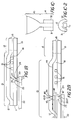
- Fig. 1A depicts a top view of a new read/write head constructed in accordance with the invention and
- Fig. 1B depicts a cross sectional view of the head depicted in Fig. 1A taken along axis X-X;
- Figs. 1C-1 and 1C-2 depict a front and end detail view, respectively of an alternate pole tip for the head depicted in Fig. 1A; and
- Fig. 2A depicts a top view of a second read/write head constructed in accordance with the invention and Fig. 2B depicts a cross sectional view of the head depicted in Fig. 2A.
- With reference to Figs. 1A and 1B, a new read/write head 10 constructed in accordance with the invention includes two
pole pieces 11 and 12 formed of a magnetic material separated by alayer 18 of insulation such as a hard-baked photoresist. Each pole piece defines a relativelylarge yoke region 13 which tapers to apole tip 14 having anend 15. In operation, the head is suspended from an arm (not shown) so that theend 15 is generally directed toward the surface of a spinning disk (not shown) which has a magnetic media thereon, and the far end of the yoke region 13 (to the left as shown in Fig. 1B) will be distal from the disk surface. The head has an axis indicated by the legend X-X, and the arm holds the head so that the axis X-X is generally orthogonal to the disk surface. - Head 10 also includes a multiple-turn planar helical coil 16 (a portion of which is depicted in Fig. 1A) positioned between the
pole pieces 11 and 12 in the yoke region to generate magnetic flux for writing data onto the disk as described below. At the left end of theyoke region 13, thepole pieces 11 and 12 touch so as to encircle a portion of the coil to provide a complete path of magnetic material between the pole pieces in theyoke region 13. Otherwise, a separation is maintained between the pole pieces in both theyoke region 13 and thepole tip 14. In the yoke region, the separation between thepole pieces 11 and 12 may be relatively large, to allow the pole pieces to accommodate thecoil 16 and ensure that there is minimal flux leakage between the pole pieces. In the pole tip, however, the separation between the pole pieces is relatively small. - In accordance with one aspect of the invention, a
slot 17 is formed inyoke region 13 of one pole piece in an orientation which is generally parallel to the expected orientation of the disk surface. That is, the orientation of theslot 17 is generally orthogonal to axis X-X. In the embodiment depicted in Fig. 1, the slot is formed in pole piece 11. Adjacent the slot, astrip 20 of magneto-resistive material, such as a nickel iron alloy (such as "Permalloy"), is positioned, electrically insulated from the pole piece 11 by a thin, non-magnetic insulator such as alumina or silicon dioxide. The strip is formed so as to have a single magnetic domain with its magnetic dipoles situated parallel to the strip's longitudinal axis, that is perpendicular to the aixs X-X. The ends of the magneto-resistive strip 20 are connected toelectrodes walls slot 17 are not disposed orthogonally to strip 20, but instead are slanted at an acute angle with respect to thestrip 20 so as to form pointededges strip 20, as is shown in Fig. 1B. - As described above, the
coil 16 is used during a writing operation, in which magnetic signals representing digital data are impressed in the magnetic media comprising the disk surface. During a writing operation, an electrical signal representing the digital data is applied to thecoil 16. The electrical signal applied tocoil 16 varies to define the digital data to be recorded in a known manner. In response to the electrical signal, the coil generates magnetic flux in the pole pieces. Assuming that, at one instance, the electrical signal is conditioned to enable the coil to generate magnetic flux upwardly (as shown in Fig. 1B) and forwardly (as shown in the Fig. 1A), that is, in the direction towardpole piece 12, the magnetic flux is first received inpole piece 12 in theyoke region 13. The flux travels inpole piece 12 through the yoke region toward the pole tip. Because the pole tip has a smaller cross-sectional area than the yoke region, the flux is concentrated in the gap; that is, the amount of flux per unit area in the gap is greater than in the yoke region. At theend 15 ofpole piece 12, the flux exits the pole piece and goes through the magnetic surface of the disk thereby impressing the magnetic flux in the magnetic media that is then adjacent the gap. - The flux returns from the disk through
end 15 of pole piece 11. From there, it goes through the pole tip of pole piece 11 to the pole piece's yoke region. The larger yoke region permits the flux to spread out. Atslot 17, thepointed edge 26 adjacent the magneto-resistive strip 20 concentrates the flux and directs it through thestrip 20, which conducts it to edge 27.Edge 27 receives the flux from magneto-resistive strip 20 and directs it to the distal end of theyoke region 13 of pole piece 11. Since the flux during a write operation is generally very large, the magneto-resistive strip essentially saturates and largely acts as an air gap across theslot 17. - It will also be appreciated that, if at some instances the magnetic flux generated by
coil 16 has the opposite direction from that described above, the path of the flux through the pole pieces and disk's magnetic media is also reversed. Thus, thepole pieces 11 and 12, the disk magnetic media andstrip 20 form a complete magnetic circuit for the flux generated bycoil 16 during a writing operation. In addition, with the disk spinning under the head, the arm (not shown) maintaining the head over one track on the disk, the varying magnetic flux generated by head 10 in response to the variations in the digital data is applied to the magnetic media along the track. Accordingly, the flux changes representative of the digital data are impressed along the track on the disk. - In accordance with another aspect of the invention, while, or immediately after, the data is written, a current IΣ is applied to
wires 30 positioned underneath the ends of the magneto-resistive strip 20. The current applied to thewires 30 establishes a small magnetic field in the magneto-resistive strip 20, which enables the magnetic dipoles in the strip, which during the writing operation had been in an orientation parallel to the axis X-X (that is, orthogonal to the longitudinal axis of the strip 20) to orient themselves in one direction along the longitudinal axis. In effect, the write flux through the magneto-resistive strip 20 forces the strip's dipoles in an orientation orthogonal to the longitudinal direction. When the write flux is removed, the dipoles may return to a longitudinal orientation, but in either direction. The magnetic field applied by thewires 30 enable the dipoles to return to a selected direction, which is determined by the field generated by the wires. Accordingly, thewires 30, and application of current thereto after the writing operation, maintain the magneto-resistive strip in a single magnetic domain. - After data has been written, it may be read by positioning the read/write head 10 over the disk track on which the data has been written. During a reading operation, a constant current Ibias is applied to the
coil 16. As a result of this current, a constant magnetic flux is generated, which is applied to thepole pieces 11 and 12, and, accordingly, to magneto-resistive strip 20. This flux is a bias flux in the magneto-resistive strip 20. The current which generates the reference flux is high enough to generate sufficient flux to be used as a biasing flux, but is small enough that the flux does not interfere with the data which has been recorded on the disk. - As the disk moves adjacent the
end 15, the transitions in the flux recorded on the disk provides magnetic flux which permeates thepole pieces 11 and 12 through theend 15 of thepole tip 14. The magneto-resitive strip 20 essentially senses the flux in the pole piece 11 in which it is situated. The flux permeating theother pole piece 12 has little effect onstrip 20. It will be appreciated that theedges resistive strip 20 and to reduce fringing edge effects of the magnetic flux at thewalls resistive strip 20. - Sensing equipment (not shown) applies a current Is between the
electrodes resistive strip 20, and specifically the changes in the resistance of the portion of the strip between end faces 28 and 29 of theelectrodes end 15 of head 10, the changes in the voltage level, relative to the voltage level resulting from only the bias flux fromcoil 16, are directly related to the changes in the resistance of the magneto-resistive material, and, accordingly, the change in the flux pattern on the disk. - It will be appreciated that two factors limit the density with which data can be recorded on the disk, namely, the number of tracks which can be recorded per unit of radius of the disk, and the number of flux transitions which may be recorded per length of track. The number of tracks per unit of radius is, in turn, related to the width of the
pole pieces 11 and 12 at theend 15. Thus, the wider the pole pieces atend 15, the fewer the number of tracks which may be recorded per unit of radius. - The number of flux transitions which may be recorded per length of track is related to several factors, including the width of the gap, that is, the distance between pole pieces at
end 15. It will be appreciated that the larger the gap width, the less data may be recorded on a track. - The arrangement depicted in the Figs. 1A and 1B permits both the width of the pole pieces at
end 15 and the gap width to be minimized, thus enhancing the density of data which may be recorded, while using a magneto-resistive strip 20 of sufficient length to minimize the effects of the Barkhausen noise due to creation of multiple magnetic domains at the ends of the magneto-resistive strip 20. In prior heads in which the magneto-resistive strip was placed in the gap, the gap had to be of greater width to accommodate the strip In addition, in the head described in the aforementioned U.S. Patent No. 4,535,375, the head is relatively long to minimize the Barkhausen noise, but the length is constrained by the desired track density. - By removing the magneto-
resistive strip 20 from thepole tip 14 and placing it in theyoke region 13, both the width of the pole pieces and the width of the gap atend 15 may be made smaller. Since the width of the pole pieces in theyoke region 13 is much larger than width in the pole tip, the magneto-resistive strip 20 may be made longer, thus minimizing the Barkhausen noise due to end effects. Thecoil 30 further reduces Barkhausen noise in the other portions of the strip by urging the magnetic dipoles in a common direction following writing operations. - In addition, since the width of the
pole pieces 11 and 12 in theyoke region 13 of the new read/write head is independent of the track density, the length of the magneto-resistive strip between theends electrodes resistive strip 20 between thesensing electrodes strip 20 in the new head is in theyoke region 13, the portion of the strip between theelectrodes - Fig. 1C-1 and 1C-2 depict a detail of a modification of the
pole tip region 14 to provideside shields pole tip portion 14 ofpole piece 12, and depend along the side of thepole tip portion 14 of pole piece 11. The side shields 31 and 32 may be formed from the same magnetic material comprising thepole pieces 11 and 12. - In operation, the side shields 31 and 32 shield the
pole tip portion 14 of pole piece 11 from fringing flux from adjacent tracks during a reading operation. The fringing flux from adjacent tracks can permeate the pole piece in the same manner as flux from the track the head 10 is reading and can result in noise in the signal obtained by the sensing equipment (not shown) that is connected to the head. Since, as described above, the output from the magneto-resistive strip 20 relates to the magnetic flux permeating pole piece 11, and is substantially unrelated to the flux permeatingpole piece 12, with the side shields 31 and 32 the magneto-resistive strip is not effected by the fringing flux from the adjacent tracks. Thus, by shielding the head from the fringing flux, theside shield - Fig. 2 depicts another read/write head 40 which is similar to head 10 (Fig. 1), with the addition of a slot 41 in the
yoke region 13 ofpole piece 12 and the positioning of a portion of a magneto-resistive strip 42 therein, separated frompole piece 12 by an insulatinglayer 49, which is similar to insulatinglayer 19. Elements of head 40 which are similar to the elements of head 10 have common reference numerals. Likeslot 17, slot 41 includessurfaces pole piece 12 so as to formedges 45 and 46 adjacent thestrip 42.Strip 42 is generally in the shape of a U, withportions slots 17 and 41, respectively, and a connectingportion 49 connecting theportions Electrodes portion 47 ofstrip 42, and a second pair ofelectrodes 50 and 51 is positioned adjacent to and in electrical contact withportion 48. If the head 40 is formed using conventional thin-film techniques, the connectingportion 49 may be a via formed using conventional techniques. - The operation of read/write head 40 (Fig. 2A) is similar to that of head 10 (Fig. 1), with the addition that, during a read operation, the the flux permeating both
pole pieces 11 and 12 will affect the resistance ofstrip 42, whereas with head 10 the resistance ofstrip 20 is affected primarily by the flux permeating the pole piece 11 adjacent thestrip 20. Accordingly, the signal sensed by the sensing equipment (not shown) connected toelectrodes pole pieces 11 and 12 of head 40 (Fig. 2A) would be more symmetric than would be the signal sensed by sensing equipment connected toelectrodes - Furthermore, with the strip 42 (Fig. 3) effectively long in the shape of a horseshoe magnet, the strip is more resistant to formation of multiple magnetic domains by externally applied magnetic flux which is present, in particular, during writing operations.
- It will be appreciated by those skilled in the art that additional slots may be formed in the pole pieces to accommodate additional portions of a magneto-resistive strip. In such heads, a single magneto-resistive strip will be positioned, in a serpentine configuration, adjacent all of said slots. The longer magneto-
resistive strip 20 will serve to further minimize the Barkhausen noise, and will also serve to increase the sensitivity of the head to the flux read from the disk. - It will also be appreciated that the particular placement of the magneto-resistive strips depicted in the Figures, that is, generally beneath the
respective pole pieces 11 and 12, is by way of example and not of limitation. In particular, during some thin film manufacturing processes, it is desirable to form the magneto-resistive strips prior to formation of the adjacent pole pieces to ensure that the magneto-resistive strips are formed on a relatively planar surface. The particular side of the respective pole pieces on which the magneto-resistive strips are formed does not effect the operation of the respective heads 10 and 40. - The foregoing description has been limited to a specific embodiment of this invention. It will be apparent, however, that variations and modifications may be made to the invention, with the attainment of some or all of the advantages of the invention, which fall within the scope of the appended claims.
Claims (8)
- A read/write head for use in a magnetic storage device in a digital data processing system for writing data in the form of magnetic flux onto, and reading data from, a magnetic media which moves relative to the head, the head having two magnetic pole pieces (11, 12) each with a yoke region (13), an energizable coil (16) situated between the pole pieces in the yoke region for generating magnetic flux, one of the pole pieces having a slot (17) in the yoke region, the head further including a strip of magneto-resistive material (20) adjacent and oriented generally transverse to the intended path of magnetic flux traversing the slot, an electrically insulating layer (19) separating the magneto-resistive strip from the slotted pole piece said strip (20) being adapted to be connected to sensing equipment such that as the media is moved relative to the head the resistance of the magneto-resistive strip varies in response to the variations in the magnetic flux recorded onto the media the sensing equipment sensing the variations in the resistance of the magneto-resistive strip, in which the magnetic pole pieces (11,12) are shaped to provide a narrow tip portion (14) and a wide yoke portion (13) and a variable width region joining the narrow tip portion (14) to the wide yoke portion 13 and characterised in that the pole piece slot (17) is situated in the wide yoke portion (13) of the magnetic pole piece (11), the magneto-resistive strip (20) protrudes beyond the ends of the pole piece slot (17) a sufficient amount to minimize the effects of the Barkhausen noise due to the creation of multiple magnetic domains at the ends of the magneto-resistive strip (20) and sensing electrodes (21,22) are connected to the magneto-resistive strip (20) at the ends of the slot (17).
- A head as defined in claim 1 further comprising means connected to said coil (16) for supplying a varying current to energize said coil (16) during a write operation and a constant current to energize said coil during a read operation, the energization of said coil during a read operation being sufficient to provide a bias magnetization to said magneto-resistive strip (20) to a substantially linear magnetic flux-electrical resistance region.
- A head as defined in claim 1 wherein said magneto-resistive strip (20) is formed having a single magnetic domain defined by magnetic dipoles having a selected orientation with respect to the strip's longitudinal axis, said head further comprising second energizable coil means (30) proximate said magneto-resistive strip (20) and oriented so as to generate a magnetic field coaxial with said strip's longitudinal axis adapted to be energized at the end of a writing operation to force the magnetic dipoles into the selected orientation.
- A head as defined in claim 1 wherein both pole pieces (11,12) have slots (17,41) formed in their respective yoke regions, the slots (17,41) being generally parallel to each other, the magneto-resistive strip (20) comprising a U-shaped member having straight portions adjacent and oriented transverse to magnetic flux traversing the respective slots.
- A head as defined in claim 1 wherein the pole piece (12) without the slot further includes a side shield (31,32) extending from the pole tip (14) thereof around the side of the pole tip (14) of the other pole piece, so that when the head is being used the side shield (31,32) operates to shield the pole tip of the other pole piece from fringing flux from adjacent tracks.
- A head as defined in any preceding claim wherein the slot (17,41) in the yoke region is formed substantially parallel to the plane of the media during operation and the strip of magneto-resistive material (20) is formed having a single magnetic domain defined by magnetic dipoles having a selected orientation with respect to the strip's longitudinal axis.
- A head as defined in any preceding claim wherein the pole pieces (11,12) are separated by a distance which is relatively large in the yoke region (13) to accommodate the energizable coil (16) and relatively small in the pole piece region (14) to increase the data density on the magnetic medium, one of the pole pieces (11) having a slot (17) in the yoke region (13) which has walls (23,24) making an acute angle relative to the exterior surface of the yoke.
- A head as defined in claim 7 where said energizable coil (16) has multiple turns, and is planar and helical.
Applications Claiming Priority (3)
| Application Number | Priority Date | Filing Date | Title |
|---|---|---|---|
| US3344687A | 1987-04-01 | 1987-04-01 | |
| US33446 | 1987-04-01 | ||
| PCT/US1988/000908 WO1988007741A1 (en) | 1987-04-01 | 1988-03-21 | Magneto-resistive thin film head for digital magnetic storage device |
Publications (2)
| Publication Number | Publication Date |
|---|---|
| EP0308483A1 EP0308483A1 (en) | 1989-03-29 |
| EP0308483B1 true EP0308483B1 (en) | 1994-12-28 |
Family
ID=21870447
Family Applications (1)
| Application Number | Title | Priority Date | Filing Date |
|---|---|---|---|
| EP88903602A Expired - Lifetime EP0308483B1 (en) | 1987-04-01 | 1988-03-21 | Magneto-resistive thin film head for digital magnetic storage device |
Country Status (8)
| Country | Link |
|---|---|
| EP (1) | EP0308483B1 (en) |
| JP (1) | JPH0738251B2 (en) |
| KR (1) | KR930005338B1 (en) |
| AU (1) | AU1628188A (en) |
| CA (1) | CA1301315C (en) |
| DE (1) | DE3852593T2 (en) |
| HK (1) | HK174595A (en) |
| WO (1) | WO1988007741A1 (en) |
Families Citing this family (13)
| Publication number | Priority date | Publication date | Assignee | Title |
|---|---|---|---|---|
| US5081554A (en) * | 1987-04-01 | 1992-01-14 | Digital Equipment Corporation | Biasing conductor for MR head |
| US4935832A (en) * | 1987-04-01 | 1990-06-19 | Digital Equipment Corporation | Recording heads with side shields |
| US5068959A (en) * | 1988-07-11 | 1991-12-03 | Digital Equipment Corporation | Method of manufacturing a thin film head |
| KR940004989B1 (en) * | 1989-08-04 | 1994-06-09 | 마쯔시다덴기산교 가부시기가이샤 | Thin film magnetic head |
| JP2563597B2 (en) * | 1989-08-04 | 1996-12-11 | 松下電器産業株式会社 | Composite thin film magnetic head |
| FR2657189B1 (en) * | 1990-01-18 | 1993-12-31 | Commissariat A Energie Atomique | MAGNETIC READING AND WRITING HEAD WITH MAGNETORESISTANT ELEMENT. |
| EP0519182B1 (en) * | 1991-04-22 | 1997-02-12 | Sharp Kabushiki Kaisha | Combined thin film magnetic head |
| US5255141A (en) * | 1991-12-16 | 1993-10-19 | Read-Rite Corp. | Read-write magnetic head with flux sensing read element |
| JPH06251339A (en) * | 1993-02-26 | 1994-09-09 | Sony Corp | Magnetoresistive thin film magnetic head and bias characteristic measuring method |
| JP2788403B2 (en) * | 1993-03-18 | 1998-08-20 | 富士通株式会社 | Magnetoresistive head |
| FR2709855B1 (en) * | 1993-09-06 | 1995-10-20 | Commissariat Energie Atomique | Magnetic read and write head with magnetoresistive element compensated for writing. |
| EP0651374A3 (en) * | 1993-11-01 | 1995-09-06 | Hewlett Packard Co | A planar magnetoresistive head. |
| FR2715507B1 (en) * | 1994-01-25 | 1996-04-05 | Commissariat Energie Atomique | Multilayer polarized magnetoresistance. |
Family Cites Families (6)
| Publication number | Priority date | Publication date | Assignee | Title |
|---|---|---|---|---|
| US3921217A (en) * | 1971-12-27 | 1975-11-18 | Ibm | Three-legged magnetic recording head using a magnetorestive element |
| US4300177A (en) * | 1975-07-17 | 1981-11-10 | U.S. Philips Corporation | Thin-film magnetic head for reading and writing information |
| US4164770A (en) * | 1977-09-21 | 1979-08-14 | Eastman Technology, Inc. | Thin film magnetoresistive head |
| DE3014459A1 (en) * | 1980-04-15 | 1981-10-22 | Siemens AG, 1000 Berlin und 8000 München | SHIELDED MAGNETORESISTIVE SENSOR FOR SCANNING INFORMATION TRACKS FROM A MAGNETIC RECORDING CARRIER |
| US4626946A (en) * | 1984-02-28 | 1986-12-02 | International Business Machines Corporation | Twin track vertical read-write head structure |
| JPH0630130B2 (en) * | 1984-08-11 | 1994-04-20 | 富士通株式会社 | Method of manufacturing thin film magnetic head |
-
1988
- 1988-03-21 AU AU16281/88A patent/AU1628188A/en not_active Abandoned
- 1988-03-21 DE DE3852593T patent/DE3852593T2/en not_active Expired - Fee Related
- 1988-03-21 EP EP88903602A patent/EP0308483B1/en not_active Expired - Lifetime
- 1988-03-21 JP JP63503548A patent/JPH0738251B2/en not_active Expired - Lifetime
- 1988-03-21 KR KR1019880701579A patent/KR930005338B1/en not_active Expired - Fee Related
- 1988-03-21 WO PCT/US1988/000908 patent/WO1988007741A1/en not_active Ceased
- 1988-03-31 CA CA000563066A patent/CA1301315C/en not_active Expired - Fee Related
-
1995
- 1995-11-16 HK HK174595A patent/HK174595A/en not_active IP Right Cessation
Also Published As
| Publication number | Publication date |
|---|---|
| DE3852593T2 (en) | 1995-07-27 |
| KR930005338B1 (en) | 1993-06-17 |
| DE3852593D1 (en) | 1995-02-09 |
| EP0308483A1 (en) | 1989-03-29 |
| JPH0738251B2 (en) | 1995-04-26 |
| WO1988007741A1 (en) | 1988-10-06 |
| KR890700890A (en) | 1989-04-28 |
| AU1628188A (en) | 1988-11-02 |
| JPH01503500A (en) | 1989-11-22 |
| CA1301315C (en) | 1992-05-19 |
| HK174595A (en) | 1995-11-24 |
Similar Documents
| Publication | Publication Date | Title |
|---|---|---|
| US4885649A (en) | Thin film head having a magneto-restrictive read element | |
| US5081554A (en) | Biasing conductor for MR head | |
| KR100259429B1 (en) | Spin valve sensor with enhanced magnetoresistance | |
| US5159511A (en) | Biasing conductor for MR head | |
| US4713708A (en) | Magnetoresistive read transducer | |
| KR940009723B1 (en) | Thin film magnetic head manufacturing method and magnetic information storage device embedded therein | |
| KR100202800B1 (en) | Yoke spin valve magnetoresistive readhead | |
| US4644432A (en) | Three pole single element magnetic read/write head | |
| EP0021392A1 (en) | Magnetic transducing head assemblies | |
| CA1301315C (en) | Magneto-resistive thin film head for digital magnetic storage device | |
| US6191925B1 (en) | Dual element read with shaped elements | |
| US5986856A (en) | Magnetoresistive sensor with improved stability | |
| US5742457A (en) | Horizontal shared-pole magnetic read/write head having polarization conductor disabling write pole | |
| US4547824A (en) | Dual biasing for integrated inductive MR head | |
| EP0573155B1 (en) | Magnetoresistive transducer conductor configuration | |
| KR100373672B1 (en) | Magnetic head, magnetic head manufacturing method and vertical magnetic recording apparatus | |
| US7187519B2 (en) | High gradient disc drive writer | |
| US5491606A (en) | Planar magnetoresistive head with an improved gap structure | |
| KR0145034B1 (en) | Magnetic transducer and a media drive containing the magnetic transducer | |
| US4737873A (en) | Magnetic writing transducer for transverse recording | |
| JPS63108503A (en) | Double track magnetic data recording method and apparatus | |
| EP0265798A2 (en) | A magnetoresistive read transducer | |
| JPH05151536A (en) | Coupling reading/writing magnetic head | |
| US6600636B1 (en) | Magnetic head with write element offset from read element | |
| EP0834864B1 (en) | Actively stabilized magnetoresistive head |
Legal Events
| Date | Code | Title | Description |
|---|---|---|---|
| PUAI | Public reference made under article 153(3) epc to a published international application that has entered the european phase |
Free format text: ORIGINAL CODE: 0009012 |
|
| 17P | Request for examination filed |
Effective date: 19881220 |
|
| AK | Designated contracting states |
Kind code of ref document: A1 Designated state(s): DE FR GB IT NL |
|
| 17Q | First examination report despatched |
Effective date: 19900924 |
|
| GRAA | (expected) grant |
Free format text: ORIGINAL CODE: 0009210 |
|
| PG25 | Lapsed in a contracting state [announced via postgrant information from national office to epo] |
Ref country code: NL Effective date: 19941228 |
|
| REF | Corresponds to: |
Ref document number: 3852593 Country of ref document: DE Date of ref document: 19950209 |
|
| ITF | It: translation for a ep patent filed | ||
| ET | Fr: translation filed | ||
| PGFP | Annual fee paid to national office [announced via postgrant information from national office to epo] |
Ref country code: NL Payment date: 19950331 Year of fee payment: 8 |
|
| NLV1 | Nl: lapsed or annulled due to failure to fulfill the requirements of art. 29p and 29m of the patents act | ||
| REG | Reference to a national code |
Ref country code: GB Ref legal event code: 732E |
|
| PLBE | No opposition filed within time limit |
Free format text: ORIGINAL CODE: 0009261 |
|
| STAA | Information on the status of an ep patent application or granted ep patent |
Free format text: STATUS: NO OPPOSITION FILED WITHIN TIME LIMIT |
|
| 26N | No opposition filed | ||
| PGFP | Annual fee paid to national office [announced via postgrant information from national office to epo] |
Ref country code: FR Payment date: 19980221 Year of fee payment: 11 |
|
| PGFP | Annual fee paid to national office [announced via postgrant information from national office to epo] |
Ref country code: GB Payment date: 19990303 Year of fee payment: 12 |
|
| PGFP | Annual fee paid to national office [announced via postgrant information from national office to epo] |
Ref country code: DE Payment date: 19990305 Year of fee payment: 12 |
|
| PG25 | Lapsed in a contracting state [announced via postgrant information from national office to epo] |
Ref country code: FR Free format text: LAPSE BECAUSE OF NON-PAYMENT OF DUE FEES Effective date: 19991130 |
|
| REG | Reference to a national code |
Ref country code: FR Ref legal event code: ST |
|
| PG25 | Lapsed in a contracting state [announced via postgrant information from national office to epo] |
Ref country code: GB Free format text: LAPSE BECAUSE OF NON-PAYMENT OF DUE FEES Effective date: 20000321 |
|
| GBPC | Gb: european patent ceased through non-payment of renewal fee |
Effective date: 20000321 |
|
| PG25 | Lapsed in a contracting state [announced via postgrant information from national office to epo] |
Ref country code: DE Free format text: LAPSE BECAUSE OF NON-PAYMENT OF DUE FEES Effective date: 20010103 |
|
| PG25 | Lapsed in a contracting state [announced via postgrant information from national office to epo] |
Ref country code: IT Free format text: LAPSE BECAUSE OF NON-PAYMENT OF DUE FEES;WARNING: LAPSES OF ITALIAN PATENTS WITH EFFECTIVE DATE BEFORE 2007 MAY HAVE OCCURRED AT ANY TIME BEFORE 2007. THE CORRECT EFFECTIVE DATE MAY BE DIFFERENT FROM THE ONE RECORDED. Effective date: 20050321 |
|
| APAH | Appeal reference modified |
Free format text: ORIGINAL CODE: EPIDOSCREFNO |