EP0307846B1 - Device for locking shift lever of automatic transmission - Google Patents
Device for locking shift lever of automatic transmission Download PDFInfo
- Publication number
- EP0307846B1 EP0307846B1 EP19880114888 EP88114888A EP0307846B1 EP 0307846 B1 EP0307846 B1 EP 0307846B1 EP 19880114888 EP19880114888 EP 19880114888 EP 88114888 A EP88114888 A EP 88114888A EP 0307846 B1 EP0307846 B1 EP 0307846B1
- Authority
- EP
- European Patent Office
- Prior art keywords
- shift lever
- lock
- movable member
- detent pin
- locking
- Prior art date
- Legal status (The legal status is an assumption and is not a legal conclusion. Google has not performed a legal analysis and makes no representation as to the accuracy of the status listed.)
- Expired - Lifetime
Links
- 230000005540 biological transmission Effects 0.000 title claims abstract description 13
- 230000033001 locomotion Effects 0.000 claims abstract description 22
- 230000004044 response Effects 0.000 claims abstract description 7
- 230000013011 mating Effects 0.000 claims 2
- 230000006835 compression Effects 0.000 description 10
- 238000007906 compression Methods 0.000 description 10
- 230000007246 mechanism Effects 0.000 description 8
- 230000000694 effects Effects 0.000 description 7
- 238000001514 detection method Methods 0.000 description 5
- 230000008901 benefit Effects 0.000 description 4
- 239000003990 capacitor Substances 0.000 description 3
- 230000007935 neutral effect Effects 0.000 description 3
- 238000010586 diagram Methods 0.000 description 2
- 239000000284 extract Substances 0.000 description 2
- 230000005484 gravity Effects 0.000 description 2
- 230000008859 change Effects 0.000 description 1
- 238000010276 construction Methods 0.000 description 1
- 230000006866 deterioration Effects 0.000 description 1
- 238000007599 discharging Methods 0.000 description 1
- 230000001771 impaired effect Effects 0.000 description 1
- 230000002401 inhibitory effect Effects 0.000 description 1
- 239000000463 material Substances 0.000 description 1
- 239000011435 rock Substances 0.000 description 1
Images







Classifications
-
- B—PERFORMING OPERATIONS; TRANSPORTING
- B60—VEHICLES IN GENERAL
- B60K—ARRANGEMENT OR MOUNTING OF PROPULSION UNITS OR OF TRANSMISSIONS IN VEHICLES; ARRANGEMENT OR MOUNTING OF PLURAL DIVERSE PRIME-MOVERS IN VEHICLES; AUXILIARY DRIVES FOR VEHICLES; INSTRUMENTATION OR DASHBOARDS FOR VEHICLES; ARRANGEMENTS IN CONNECTION WITH COOLING, AIR INTAKE, GAS EXHAUST OR FUEL SUPPLY OF PROPULSION UNITS IN VEHICLES
- B60K23/00—Arrangement or mounting of control devices for vehicle transmissions, or parts thereof, not otherwise provided for
-
- F—MECHANICAL ENGINEERING; LIGHTING; HEATING; WEAPONS; BLASTING
- F16—ENGINEERING ELEMENTS AND UNITS; GENERAL MEASURES FOR PRODUCING AND MAINTAINING EFFECTIVE FUNCTIONING OF MACHINES OR INSTALLATIONS; THERMAL INSULATION IN GENERAL
- F16H—GEARING
- F16H59/00—Control inputs to control units of change-speed- or reversing-gearings for conveying rotary motion
- F16H59/02—Selector apparatus
- F16H59/08—Range selector apparatus
- F16H59/10—Range selector apparatus comprising levers
-
- F—MECHANICAL ENGINEERING; LIGHTING; HEATING; WEAPONS; BLASTING
- F16—ENGINEERING ELEMENTS AND UNITS; GENERAL MEASURES FOR PRODUCING AND MAINTAINING EFFECTIVE FUNCTIONING OF MACHINES OR INSTALLATIONS; THERMAL INSULATION IN GENERAL
- F16H—GEARING
- F16H61/00—Control functions within control units of change-speed- or reversing-gearings for conveying rotary motion ; Control of exclusively fluid gearing, friction gearing, gearings with endless flexible members or other particular types of gearing
- F16H61/22—Locking of the control input devices
- F16H2061/223—Electrical gear shift lock, e.g. locking of lever in park or neutral position by electric means if brake is not applied; Key interlock, i.e. locking the key if lever is not in park position
-
- F—MECHANICAL ENGINEERING; LIGHTING; HEATING; WEAPONS; BLASTING
- F16—ENGINEERING ELEMENTS AND UNITS; GENERAL MEASURES FOR PRODUCING AND MAINTAINING EFFECTIVE FUNCTIONING OF MACHINES OR INSTALLATIONS; THERMAL INSULATION IN GENERAL
- F16H—GEARING
- F16H61/00—Control functions within control units of change-speed- or reversing-gearings for conveying rotary motion ; Control of exclusively fluid gearing, friction gearing, gearings with endless flexible members or other particular types of gearing
- F16H61/22—Locking of the control input devices
-
- Y—GENERAL TAGGING OF NEW TECHNOLOGICAL DEVELOPMENTS; GENERAL TAGGING OF CROSS-SECTIONAL TECHNOLOGIES SPANNING OVER SEVERAL SECTIONS OF THE IPC; TECHNICAL SUBJECTS COVERED BY FORMER USPC CROSS-REFERENCE ART COLLECTIONS [XRACs] AND DIGESTS
- Y10—TECHNICAL SUBJECTS COVERED BY FORMER USPC
- Y10T—TECHNICAL SUBJECTS COVERED BY FORMER US CLASSIFICATION
- Y10T70/00—Locks
- Y10T70/50—Special application
- Y10T70/5889—For automotive vehicles
- Y10T70/5925—Transmission
- Y10T70/5934—Selective-type shift rod, fork or block
-
- Y—GENERAL TAGGING OF NEW TECHNOLOGICAL DEVELOPMENTS; GENERAL TAGGING OF CROSS-SECTIONAL TECHNOLOGIES SPANNING OVER SEVERAL SECTIONS OF THE IPC; TECHNICAL SUBJECTS COVERED BY FORMER USPC CROSS-REFERENCE ART COLLECTIONS [XRACs] AND DIGESTS
- Y10—TECHNICAL SUBJECTS COVERED BY FORMER USPC
- Y10T—TECHNICAL SUBJECTS COVERED BY FORMER US CLASSIFICATION
- Y10T70/00—Locks
- Y10T70/50—Special application
- Y10T70/5889—For automotive vehicles
- Y10T70/5956—Steering mechanism with switch
Definitions
- the present invention relates to a device for locking a shift lever of an automatic transmission which is capable of inhibiting movement of the shift lever from a non-driving position such as neutral or parking position under a certain condition.
- the driver When re-starting the automobile, the driver starts the engine while the lever is still in the P position and then moves the shift lever to a D (driving) position past an R (reversing) position.
- the driver therefore, has to keep the foot brake put on during shifting from the P position to the D position, in order to prevent from reversing the automobile.
- an interlocking mechanism is employed in which the motion of the shift lever is interlocked with the state of a steering locking mechanism in such a manner that the movement of the shift lever from a non-driving position such as the P position or an N (neutral) position is prevented under a certain condition of the steering lock.
- Such an interlocking mechanism is operatively connected to a detent pin which is movable between an inoperative position and an operative position as a button on the knob of the lever is pressed and released by the driver. The operation of this button tends to be impaired due to the presence of the interlocking mechanism which is connected to the detent pin. It is also experienced that the operation of the interlocking mechanism is inconveniently influenced by the manual pressing force exerted on the button on the shift lever knob.
- an object of the present invention is to provide a device for locking an automatic transmission shift lever which is improved in such a way as to eliminate any unfavorable effect which might otherwise be caused on the operation of the shift lever knob due to the presence of an interlocking mechanism, as well as undesirable influence of the manual pressing force caused on the interlocking mechanism by the manual force exerted by the driver on the shift lever knob.
- a shift lever locking device for locking an automatic transmission shift lever which is capable of being selectively moved to and set in one of a plurality of shift positions including at least one non-driving position
- the device comprises: a detent pin provided on the shift lever and designed to be moved in one direction in response to pressing of a button provided on the shift lever; a detent plate capable of selectively latching the shift lever in one of said positions in cooperation with the detent pin and having a locking recess capable of receiving the detent pin when the detent pin is moved in the other direction after the shift lever is set in the non-driving position; a movable member capable of engaging with the detent pin at least when the detent pin is being brought into engagement with the locking recess and movable between a lock position where it engages with the detent pin so as to prevent the detent pin from moving and an unlock position where it is disengageable from the detent pin to allow the detent pin to move; and a lock member movable between
- the lock member In operation, when the predetermined condition has become to be met, the lock member is moved from the second position to the first position so as to hold the movable member in the lock position. In this state, the detent pin is not allowed to move even if the push button is pressed so that the detent pin cannot be disengaged from the locking recess, whereby the shift lever is immovably locked in the non-driving position.
- the lock member is engaged with and is releasable from the movable member when it is in the first position and in the second position, respectively.
- An automotive automatic transmission has a shift lever 1 which is swingable about a fulcrum constituted by a shaft 3 provided on a plate 2, in the direction shown by an arrow A and also in the counter direction.
- a detent plate 4 fixed to the plate 2 has an engaging aperture 6 the upper edge of which is configured in the direction of swinging of the shift lever 1 so as to provide latching steps 5 which cooperates with a later-mentioned detent pin 7 in such a manner as to selectively limit the range of the movement of the shift lever 1 when the shift lever is moved from one to another of a plurality of shift positions including a P (Parking) position, R (reverse) position, N (neutral) position, D (drive) position, 2nd range position and L (Low range) position.
- the portion of the upper edge of the aperture 6 where the detent pin 7 is located when the lever 1 is set in the P position is notched to provide a locking recess 8.
- the detent pin 7 is movable along a slot formed in the shift lever 1.
- the arrangement is such that the detent pin 7 is adapted to be moved to the lower end of the slot so as to be disengaged from the latching steps 5 when a push button 9 provided on a knob of the shift lever 1 is pushed by the driver.
- the detent pin 7 is moved upward into engagement with one of the latching steps corresponding to one of the shift lever positions P, R, D, 2nd and L, whereby the shift lever is latched at the selected position.
- a movable member 10 is slidably supported by the detent plate 4 so as to slide along a line which interconnects the shaft 3 and the locking recess 8 corresponding to the P position of the shift lever.
- the movable member 10 is provided at an upper portion thereof with an engaging recess 11 which opens to the right as viewed in Fig. 1 so as to confront the engaging aperture 6.
- the movable member 10 also is provided with an engaging step 12 on the left lower portion thereof as viewed in Fig. 1.
- a lock lever 13 as a locking member is rotatably supported by the detent plate 4.
- the lock lever 13 is allowed to swing clockwise until its upper end is brought into engagement with the engaging step 12 of the movable member 10.
- a control wire 14 is connected at its one end to the lower end of the lock member 13, while the other end of the control wire 14 is connected to a steering lock device.
- the lock lever 13 is urged in the direction counter to the arrow B, as illustrated in Fig. 1.
- the operation of this embodiment will be described hereafter.
- the lock lever 13 In the inoperative state of the steering lock device, the lock lever 13 has been rotated counter-clockwise to the position shown in Fig. 1, as explained above. It is assumed here that the shift lever 1 has been set in the N position. Movement of the shift lever 1 from the N position to the D position can be conducted without encountering any substantial resistance.
- the driver also can move the shift lever 1 from the N position to the R position and further to the P position in the direction counter to the arrow A, by pressing the push button 9 to free the detent pin 7. Returning of the shift lever 1 from the R position to the N position can be conducted without requiring pressing of the push button 9.
- the detent pin 7 is moved in the other direction which is in this case upward direction into engagement with the locking recess 8, while lifting the movable member 10 into the lock position as shown in Fig. 3.
- the lock lever 13 is rotated in the direction of the arrow B so that its end is brought into engagement with the engaging step 12. Since the movable member 10 and, hence, the detent pin 7 are prevented from moving downward in this state despite of pressing the push button 9, the detent pin 7 is received in the locking recess 8 so as to prevent the shift lever 1 from moving out of the P position.
- the steering lock device cannot be set and, at the same time, the engine key cannot be extracted unless the shift lever 1 is set in the P position.
- the engine key can be extracted only after it has been turned to the lock position which essentially requires that the shift lever 1 is set in the P position in advance. Consequently, the automobile can be set in immobile state without fall before the driver extracts the engine key from the steering lock device.
- the shift lever 1 is locked in the P position and can by no means moved to another position unless the steering lock is unlocked by the engine key. In other words, only the driver who keeps the engine key with him can unlock the shift lever 1 from the P position.
- the shift lever 1 is locked in a specific non-driving position, i.e., in the P position, on a specific condition that the steering lock device has been put into effect by the engine key.
- the arrangement may be such that shift lever 1 is locked in the P position on condition that the foot brake pedal is not been applied and unlocked upon confirming that the foot brake has been put on.
- the arrangement also may be such that the shift lever 1 is locked in the N position which also is a non-driving position.
- Fig. 4 shows a second embodiment of the present invention in which a lock plate 15, which serves as a lock member in place of the lock lever 13 of the first embodiment, is slidably carried by the detent plate 4 so as to be brought into and out of engagement with the engaging step 12 of the movable member 10.
- Other portions of the second embodiment, as well as the operation, are materially the same as those of the first embodiment.
- the third embodiment of the locking device has a shift lever 101 which is mounted on the plate 102 for swinging motion about a fulcrum provided by the shaft 103, in the direction of the arrow C and also in the direction counter to the arrow C.
- a detent plate 104 fixed to the plate 102 has, as shown in Fig. 5, an engaging aperture 105 the upper edge of which provides engaging or latching steps for latching a shift lever 101 selectively in one of the P, R, N, D 2nd and L positions along the path of the swinging motion of the shift lever 101.
- a notch is provided in the portion of the upper edge of the engaging aperture 105 corresponding to the P position of the shift lever 101, so as to provide a locking recess 106.
- a detent pin 107 is provided on a lower portion of the shift lever 101 so as to be movable in the axial direction of the shift lever 101 along an elongated slot formed in the wall of the shift lever 101 into and out of engagement with the upper edge of the engaging aperture 105 providing the latching steps.
- the arrangement is such that, when a push button 108 provided on a knob 101a of the shift lever 101 is pressed by the driver, the detent pin 107 is moved in one direction which is in this case downward direction so as to be disengaged from one of the latching steps provided by the upper edge of the engaging aperture 105.
- the detent pin 107 is moved in the other direction, i.e., upward, into engagement with one of the latching steps provided by the upper edge of the engaging aperture.
- the detent pin 107 cooperates with the detent plate 104 in limiting the movement of the shift lever 101.
- a reference numeral 109 designates a guide member which is fixed to the detent plate 104
- a numeral 110 designates a movable member which is carried by the guide member 109 for sliding movement in the direction of the arrow D and in the direction counter to the arrow D.
- the movable member 110 is provided at its upper portion with an engaging recess 111 which opens to the left as shown in Fig. 5 so as to confront the locking recess 106 in Fig. 6.
- the movable member 110 also is provided with a notched portion In the right lower portion thereof as shown in Fig. 5
- a lock lever serving as a lock member in the device of the present invention is secured to the plate 102 through a pin 114 for swinging motion about the pin 114.
- a reference numeral 115 denotes a solenoid which is provided on a lower portion of the plate 102 and which serves as an electric actuating device.
- the solenoid 115 has an actuator rod 116 which projects to the right as shown in Fig. 5.
- the actuator rod 116 carries at its end a holder 117 which is connected to a lower portion of the lock lever 113 through a pin 118.
- a coiled compression spring 119 is loaded between the holder 117 and the solenoid 115.
- the solenoid 115 is adapted to be electrically energized only when all the three conditions are simultaneously satisfied: namely, setting the shift lever 101 in the P position, switching on the ignition switch and putting on the foot brake pedal.
- the solenoid 115 As the solenoid 115 is energized, the actuator rod 116 is electromagnetically attracted in the direction of an arrow E against the force of the coiled compression spring 119 so as to swing the lock lever 113 in the direction of an arrow F. When at least one of these three conditions fails to be met, the solenoid 115 is not energized so that the actuator rod 116 is pulled by the force of the compression coiled spring 119 in the direction counter to the arrow E, thereby to cause the lock lever 113 to swing in the direction counter to the arrow F.
- a description will be made with regard to an electric circuit for controlling the solenoid 115, in accordance with Fig. 7.
- the circuit includes an ignition switch 120, a P position detection switch 121 for detecting that the shift lever is set in the P position, and a foot brake detection switch 122 which is adapted to be turned on when the foot brake pedal is pressed down.
- the circuit further includes transistors 123 to 126, capacitors 127 and 128, diodes 129 to 131, resistors 132 to 141, and a Zener diode 142.
- the operation of this circuit is as follows.
- the solenoid 115 is not energized whenever at least one of the ignition switch 120, P position detection switch 121 and the foot brake switch 122 is off. In such a state, the actuator rod 116 is urged in the direction counter to the arrow E by the force of the compression spring 119.
- the ignition switch 120 is turned on as the driver turns the ignition key.
- the P position detecting switch 121 is turned on if the shift lever 101 has been set in the P position.
- the foot brake switch 122 is turned on as the driver puts on the foot brake.
- the transistor 123 is turned on so as to turn on also the transistor 124 and further the transistors 125 and 126.
- the solenoid 115 is supplied with electric power so that the actuator rod 116 is attracted to move in the direction of the arrow E against the force of the compression coiled spring 119.
- the voltage of the electric power supplied to the solenoid 116 at the time of start-up is 12V.
- the transistor 125 is turned off as the capacitor 127 connected to the base of the transistor 125 is charged up at an instant t shown in Fig. 8. Thereafter, the solenoid 115 is energized only through the transistor 126 and the resistor 132, so that the voltage applied to the solenoid 115 is lowered to about 8 V.
- the solenoid 115 is energized only through the transistor 126 and the resistor 132, so that the voltage applied to the solenoid 115 is lowered to about 8 V.
- the foot brake pedal is not being put on while the ignition switch 120 is in the on state and the shift lever 101 is in the P position.
- the detent pin 107 is received by the locking recess 106 in the detent plate 104 and is kept in engagement with the engaging recess of the lock member 110 whereby the lock member 110 is held in the lock position.
- the solenoid 115 is kept in off state so that the actuator rod 116 of the solenoid 115 has been urged in the direction counter to the arrow E by the force of the coiled spring 119. Therefore, the lock lever has been rotated in the direction counter to the arrow F as shown by solid line, with its upped end is held in engagement with the notch 112 in the movable member 110.
- the movable member 110 which is held in engagement with the detent pin 107, is prevented from moving in the direction of the arrow D because it is stopped by the lock lever 113.
- the detent pin 107 cannot move downward even if the push button 108 on the shift lever 101 is pressed, so that the shift lever 101 cannot move from the P position to another shift position.
- the shift lever 101 is immovably locked in the P position when the foot brake pedal is not put on by the driver.
- the solenoid 115 is turned on so that the actuator 116 is attracted in the direction of the arrow E, with the result that the lock lever 113 is rotated in the direction of the arrow F as shown by two-dot-and-dash line, whereby the lock lever 113 is disengaged from the movable member 110 so as to free the movable member 110.
- the push button 108 is pressed in this state, the detent pin 107 is moved downward as indicated by the arrow D together with the movable member 110, so that the movable member 110 is set in an unlocking position as shown in Fig. 6. In this state, the detent pin 107 has been disengaged from the locking recess 106, so that the shift lever 101 can be moved from the P position to another position.
- the P position detection switch 121 is turned off so that the solenoid 115 is de-energized with the result that the lock lever 113 is urged by the force of the coiled compression spring 119 so as to bring its end into contact with the right end of the movable member 110, as will be seen in Fig. 6.
- the solenoid 115 is never energized even if the foot brake switch 122 is turned on due to pressing down of the foot brake pedal, insofar as the shift lever 101 is set in a position other than the P position.
- the detent pin 107 When the driver has moved the shift lever 101 to the P position while pressing the push button 108, the detent pin 107 is brought into engagement with the engaging recess 111 in the movable member 110. Then, as the push button is released, the detent pin 107 together with the movable member 110 is moved upward counter to the arrow D so that the detent pin 107 is brought into engagement with the locking recess 106 while the movable member 110 is set in the lock position.
- the solenoid 115 is never energized even if the ignition key is turned on while the shift lever 101 is set in the P position, unless the foot brake pedal is put on.
- the driver is obliged to apply the foot brake pedal in order to move the shift lever from the P position to another position.
- This arrangement therefore serves as a safety arrangement which eliminates the shift lever to be set in a driving position such as D, 2nd or L position from the P position while the foot brake pedal is not put on by the driver.
- the solenoid 115 is energized only when all the three conditions, i.e., setting the shift lever 101 in the P position, switching on the ignition switch 120 and applying the foot brake, are simultaneously satisfied. Therefore, the solenoid 115 is never energized even when the foot brake is pressed down while the shift lever 101 is set in a position other than the P position. Consequently, the durability of the locking and unlocking mechanism is remarkably improved as compared with an arrangement in which the rock lever 113 is mechanically connected to the foot brake so as to be rotated each time the foot brake is put on.
- the third embodiment as described also offers the following advantage.
- the lock lever 113 is disposed to act between the detent pin 107 and the actuator rod 116 of the solenoid 115. Therefore, a manual pressing force exerted on the push button 108 by the driver while the shift lever 101 is set in the P position, which force acts to move the detent pin 107 downward, is not directly transmitted to the actuator rod 116. Therefore, any risk for the actuator rod 116 to be damaged or deformed, which might be caused if the device were designed to allow the detent pin to directly act on the actuator rod 116, is avoided and smooth operation of the solenoid 115 is ensured.
- Figs. 9 and 10 show a fourth embodiment of the present invention.
- the fourth embodiment is discriminated from the third embodiment by the following feature. Namely, the fourth embodiment lacks the lock lever 113 which is arranged in the third embodiment so as to act between the movable member 110 and the solenoid 115.
- the solenoid 115 is disposed on the right side of the movable member 110. In this embodiment, therefore, the actuator rod 116 is urged in the direction counter to the arrow E by the force of the compression coiled spring 119 when the solenoid 115 is not energized while the shift lever 101 is set in the P position.
- the actuator rod 116 directly engages with the notch 112 in the movable member 110 so as to hold the movable member 110 in the lock position.
- the actuator rod 116 serves as a lock member.
- the solenoid 115 is turned on, the actuator rod 116 is attracted in the direction of the arrow E away from the movable member 110 thereby to free the lock member.
- the solenoid 115 is not energized so that the actuator rod 116 is held in contact with the right side edge of the movable member 110.
- Figs. 11 and 12 illustrate a fifth embodiment of the present invention.
- the fifth embodiment is different from the third and fourth embodiments in that the movable member 143 is rotatable about a fulcrum 144.
- the actuator rod 116 is urged in the direction counter to an arrow E by the force of the coile compression spring 119 so as to be held in engagement with a notch 145 in the movable member 143 so as to prevent the movable member 143 from rotating in the direction of the arrow H, thus holding the movable member 143 in the lock position.
- the solenoid 115 is energized, the actuator rod 116 is attracted in the direction of the arrow E as shown by two-dot-and-dash line out of engagement with the notch 145 of the movable member 143. In consequence, the movable member 143 is allowed to rotate in the direction of the arrow H.
- the solenoid 115 is not energized so that the actuator rod 116 is held in contact with the side edge of the movable member 143 as shown in Fig. 12.
- Fig. 13 illustrates a sixth embodiment of the present invention.
- the sixth embodiment is distinguished from preceding embodiments in that the solenoid 115 is arranged such that the actuator rod 116 thereof extends orthogonally to the detent plate 104.
- the solenoid 115 when the solenoid 115 is not energized, the actuator rod 116 is urged by the force of the coiled compression spring 119 in the direction counter to the arrow E as shown by solid line in Fig. 13.
- the actuator rod 116 is held in contact with the lower end of the movable member 110 so as to prevent the movable member from moving downward, thus holding the movable member 110 in the lock position.
- the actuator 116 is attracted in the direction of the arrow E away from the movable member 110 so as to free the movable member 110 as shown by two-dot-and-dash line in Fig. 13.
- the movable member is held in the lock position so as to lock the shift lever 101 when the solenoid 115 is not energized, and the movable member 110 is freed to unlock the shift lever 101 when the solenoid 115 is energized.
- the third to sixth embodiments as described may be modified such that the shift lever 101 is locked when the solenoid 115 is energized and unlocked in response to de-energization of the solenoid 115.
- the solenoid actuator used in these embodiments may be of the type in which the actuator rod, which has been moved to a position as a result of energization of the solenoid, is held in this position even when the solenoid is de-energized.
- the solenoid 115 used as an electric actuator in the third to sixth embodiments may be substituted by a different type of electric actuator such as an electric motor.
- the third to sixth embodiments may be modified such that the shift lever 101 is lockable in the N position which also is a non-driving position of the shift lever 101, although locking in the P position has been described.
- a shift lever 201 is swingable about a fulcrum constituted by a shaft 203 which is secured to a machine frame 202, in the direction of an arrow I and in the direction counter to the arrow I.
- a detent plate 204 fixed to one side of the frame 202 has an engaging aperture 206 the upper edge of which is configured so as to provide latching steps 205 which are arranged in the direction of swinging motion of the shift lever 201 as will be clearly seen in Fig. 14.
- latching steps 205 are adapted to cooperate with a later-mentioned detent pin 207 in latching the shift lever 201 selectively in one of a plurality of lever positions which are the P position, R position, N position, D position, 2nd position and the L position as shown in Fig. 14.
- a locking recess 208 is provided in the portion of the upper edge of the engaging aperture corresponding to the P position of the shift lever 201.
- the detent pin 207 is movable on the shift lever 201 in the axial direction of this lever 201.
- a reference numeral 210 designates a movable member which is provided at its upper portion with an engaging recess 211 which opens to the right as shown in Figs. 14 and 15.
- the movable member 210 also is provided at its let upper portion with an elongated hole 212 which movably receives a pin 213 provided on a portion of the detent plate 204 near the locking recess 208.
- the engaging recess 211 is movable along a line which interconnects the shaft 203 and the locking recess 208.
- a lever member 214 is rotatably supported at its one end, e.g., at the right end as illustrated, by the detent plate 204 through a shaft 215, while the other end, e.g., the left end as illustrated, is swingably connected to the lower end of the movable member 210 through the shaft 216.
- An arm 217 which is integral with the lever member 214 extends downward from the right end of the lever member 214 as shown in Fig. 14.
- a steering lock device is connected to the end of the arm 217 through a control wire which is not shown.
- the steering lock device can be set in locking condition when the lever member 214 is set in the state shown in Fig. 15.
- the lever member 214 is prevented from rotating in the direction of an arrow J.
- the arm 217 and, hence, the lever member 214 become swingable as the steering lock device is set in the unlocking condition.
- pressing of the push button 209 causes the detent pin 207 to be moved in one direction, e.g., downward as illustrated, so that the detent pin 207 can clear the above-mentioned wall of the recess defining the latching step for the D position, thus allowing the shift lever 201 to be moved to the 2nd position and further to the L position if necessary.
- Returning of the shift lever from the L position back to the N position past the 2nd and D positions can be effected without requiring pressing of the push button 209, simply by swinging the shift lever 201 in the direction counter to the arrow I, because in such a case the detent pin 207 can slide along the successive latching steps 205 without being stopped.
- the shift lever 201 is movable from the N position to the R and P positions by swinging the same in the direction counter to the arrow I.
- the shifting of the shift lever 201 from the R position to the N position can be conducted without requiring pressing of the push button 209.
- the movable member 210 When the shift lever 201 is in a position other than the P position, the movable member 210 has been lowered due to the force of gravity so that the arm 217 has been rotated in the direction of the arrow J to the position shown in Fig. 14. In this state, the steering lock device cannot be set to the locking condition as explained before. In this state, the engine key, which has been rotated to the engine-off position, cannot be turned to the steering lock position so that the engine key cannot be extracted from the steering lock device.
- the detent pin 207 is brought into engagement with the engaging recess 211 in the movable member 210 which is now in the lowered position and, as the push button 209 is released after the shift lever 201 has been brought to the P position, the detent pin 207 is moved in the other direction, i.e., upward, into engagement with the locking recess 208 while lifting the movable member 210 to the raised position as shown in Fig. 15.
- the lever member 214 is rotated in the direction counter to the arrow J to the position shown in Fig.
- the steering lock device becomes lock able the steering system.
- the engine key can be turned to the steering lock position so that it can be extracted from the steering lock device.
- the lever member 214 becomes unable to rotate in the direction of the arrow J. In this state, therefore, the movement of the detent pin in one direction, i.e., downward direction, is inhibited so that the detent pin 207 cannot be disengaged from the locking recess 208, whereby undesirable shift of the shift lever 201 from the P position is avoided.
- the steering lock device cannot be put into effect and, therefore, the engine key cannot be extracted from the steering lock device unless the shift lever of the automatic transmission is set in the P position.
- the seventh embodiment also prevents the engine key from being extracted during running the automobile.
- the engine key can be extracted only after the steering lock device is put into effect which in turn essentially requires that the shift lever 201 is set in the P position.
- the driver can lock the automobile in immobile state without fail whenever the driver extracts the key from the steering device.
- the shift lever 201 set in the P position also is locked in this position so that the shift lever 201 can no more be operated by any person other than the driver who carries the engine key with him.
- the seventh embodiment as described offers an additional advantage in that the stress can conveniently be distributed by virtue of the articulated construction employing the shaft or pin 216 through which the movable member 210 and the lever member 214 are connected to each other. This in turn allows these parts to be manufactured from less-expensive materials.
- the shift lever 210 is locked in the P position as a non-driving position on condition that the steering system is locked by means of the engine key, this is only illustrative and the arrangement may be such that the shift lever 201 is locked in the P position on condition that the foot brake pedal has not been put on and unlocked on condition that the same pedal has been put on.
- An automatic shift lever locking device is capable of locking the shift lever of an automatic transmission in a specific non-driving shift position against movement from this position unless a predetermined condition is met.
- the device has a detent pin provided on the shift lever and movable in response to pressing of a push button on the shift lever, a movable member engageable with the detent pin, and a lock member engageable with the movable member so as to prevent the detent pin from moving out a lock position thereby to maintain the shift lever locked in the non-driving position. Therefore, when the shift lever is not locked, the manual force exerted by the driver on the push button is not transmitted to the lock members and other parts mechanically connected to the lock member.
Landscapes
- Engineering & Computer Science (AREA)
- General Engineering & Computer Science (AREA)
- Mechanical Engineering (AREA)
- Chemical & Material Sciences (AREA)
- Combustion & Propulsion (AREA)
- Transportation (AREA)
- Arrangement Or Mounting Of Control Devices For Change-Speed Gearing (AREA)
- Control Of Transmission Device (AREA)
Abstract
Description
- The present invention relates to a device for locking a shift lever of an automatic transmission which is capable of inhibiting movement of the shift lever from a non-driving position such as neutral or parking position under a certain condition.
- When parking an automobile with an automatic transmission, it is a common practice to set the automobile in immobile state by putting a parking brake into effect and setting the automatic transmission shift lever at a P (parking) position before leaving the automobile.
- When re-starting the automobile, the driver starts the engine while the lever is still in the P position and then moves the shift lever to a D (driving) position past an R (reversing) position. The driver, therefore, has to keep the foot brake put on during shifting from the P position to the D position, in order to prevent from reversing the automobile.
- Usually, the motion of the shift lever is interlocked with various other functions. For instance, an interlocking mechanism is employed in which the motion of the shift lever is interlocked with the state of a steering locking mechanism in such a manner that the movement of the shift lever from a non-driving position such as the P position or an N (neutral) position is prevented under a certain condition of the steering lock. Such an interlocking mechanism is operatively connected to a detent pin which is movable between an inoperative position and an operative position as a button on the knob of the lever is pressed and released by the driver. The operation of this button tends to be impaired due to the presence of the interlocking mechanism which is connected to the detent pin. It is also experienced that the operation of the interlocking mechanism is inconveniently influenced by the manual pressing force exerted on the button on the shift lever knob.
- Accordingly, an object of the present invention is to provide a device for locking an automatic transmission shift lever which is improved in such a way as to eliminate any unfavorable effect which might otherwise be caused on the operation of the shift lever knob due to the presence of an interlocking mechanism, as well as undesirable influence of the manual pressing force caused on the interlocking mechanism by the manual force exerted by the driver on the shift lever knob.
- To these ends, according to the present invention, there is provided a shift lever locking device for locking an automatic transmission shift lever which is capable of being selectively moved to and set in one of a plurality of shift positions including at least one non-driving position, the device comprises: a detent pin provided on the shift lever and designed to be moved in one direction in response to pressing of a button provided on the shift lever; a detent plate capable of selectively latching the shift lever in one of said positions in cooperation with the detent pin and having a locking recess capable of receiving the detent pin when the detent pin is moved in the other direction after the shift lever is set in the non-driving position; a movable member capable of engaging with the detent pin at least when the detent pin is being brought into engagement with the locking recess and movable between a lock position where it engages with the detent pin so as to prevent the detent pin from moving and an unlock position where it is disengageable from the detent pin to allow the detent pin to move; and a lock member movable between a first position where it pevents the movable member from moving from the lock position and a second position-where it allows the movable member to move from the lock position to the unlock position and capable of being moved from the second position to the first position when a predetermined condition is met while the shift lever is set in the non-driving position.
- In operation, when the predetermined condition has become to be met, the lock member is moved from the second position to the first position so as to hold the movable member in the lock position. In this state, the detent pin is not allowed to move even if the push button is pressed so that the detent pin cannot be disengaged from the locking recess, whereby the shift lever is immovably locked in the non-driving position.
- In a first aspect of the invention, the lock member is engaged with and is releasable from the movable member when it is in the first position and in the second position, respectively.
- Therefore, when the lock member is in the second position, the manual pressing force exerted on the push button by the driver is not transmitted to the lock member and other parts mechanically connected to the lock member, whereby any deterioration of the operation of the button which might otherwise be caused can be avoided. These and other objects, features and advantages of the present invention will become clear from the following description of the preferred embodiments when the same is read in conjunction with the accompanying drawings, in which:
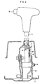
- Fig. 1 is a partly-sectioned side elevational view of an embodiment of the device of the present invention for locking the shift lever of an automatic transmisison;
- Fig. 2 is a vertical sectional view of the embodiment shown in Fig. 1;
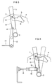
- Fig. 3 is an illustration of operation of the embodiment shown in Fig. 1;
- Fig. 4 is a schematic illustration of a second embodiment of the present invention;
- Fig. 5 is a partly-sectioned schematic side elevational view of a third embodiment of the present invention;
- Fig. 6 is a view corresponding to Fig. 5 but showing the third embodiment in a different state of operation from the state shown in Fig. 5;
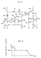
- Fig. 7 is a circuit diagram of an electrical circuit incorporated in the third embodiment;
- Fig. 8 is a diagram showing a change in a voltage which is applied to a solenoid;
- Fig. 9 is a view corresponding to that in Fig. 5 but showing a fourth embodiment of the present invention;
- Fig. 10 is a view corresponding to Fig. 6;
- Fig. 11 is a view corresponding to that in Fig. 5 but showing a fifth embodiment of the present invention;
- Fig. 12 is a view corresponding to Fig. 6 but showing the fifth embodiment of the present invention;
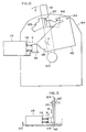
- Fig. 13 is a sectional front elevational view of an essential portion of a sixth embodiment of the present invention;
- Fig. 14 is a partly-sectioned side elevational view of a seventh embodiment of the present invention; and
- Fig. 15 is a partly-sectioned side elevational view of the seventh embodiment in a state different from that shown in Fig. 14.
- A first embodiment of the present invention will be described with reference to Figs. 1 to 3. An automotive automatic transmission has a
shift lever 1 which is swingable about a fulcrum constituted by ashaft 3 provided on aplate 2, in the direction shown by an arrow A and also in the counter direction. Adetent plate 4 fixed to theplate 2 has anengaging aperture 6 the upper edge of which is configured in the direction of swinging of theshift lever 1 so as to providelatching steps 5 which cooperates with a later-mentioneddetent pin 7 in such a manner as to selectively limit the range of the movement of theshift lever 1 when the shift lever is moved from one to another of a plurality of shift positions including a P (Parking) position, R (reverse) position, N (neutral) position, D (drive) position, 2nd range position and L (Low range) position. The portion of the upper edge of theaperture 6 where thedetent pin 7 is located when thelever 1 is set in the P position is notched to provide alocking recess 8. - The
detent pin 7 is movable along a slot formed in theshift lever 1. The arrangement is such that thedetent pin 7 is adapted to be moved to the lower end of the slot so as to be disengaged from thelatching steps 5 when apush button 9 provided on a knob of theshift lever 1 is pushed by the driver. As the push button is released, thedetent pin 7 is moved upward into engagement with one of the latching steps corresponding to one of the shift lever positions P, R, D, 2nd and L, whereby the shift lever is latched at the selected position. Amovable member 10 is slidably supported by thedetent plate 4 so as to slide along a line which interconnects theshaft 3 and the locking recess 8 corresponding to the P position of the shift lever. Themovable member 10 is provided at an upper portion thereof with an engaging recess 11 which opens to the right as viewed in Fig. 1 so as to confront theengaging aperture 6. Themovable member 10 also is provided with anengaging step 12 on the left lower portion thereof as viewed in Fig. 1. Alock lever 13 as a locking member is rotatably supported by thedetent plate 4. When themovable member 10 is set in a lower position as shown in Fig. 1, the upper portion of thelock lever 13 abuts the side surface of themovable member 10 so as to be prevented from swinging clockwise, i.e., in the direction of an arrow B, whereas, when themovable member 10 is locked in an upper lock position as shown in Fig. 3, thelock lever 13 is allowed to swing clockwise until its upper end is brought into engagement with theengaging step 12 of themovable member 10. Acontrol wire 14 is connected at its one end to the lower end of thelock member 13, while the other end of thecontrol wire 14 is connected to a steering lock device. When the steering lock device has been dismissed, thelock lever 13 is urged in the direction counter to the arrow B, as illustrated in Fig. 1. The operation of this embodiment will be described hereafter. In the inoperative state of the steering lock device, thelock lever 13 has been rotated counter-clockwise to the position shown in Fig. 1, as explained above. It is assumed here that theshift lever 1 has been set in the N position. Movement of theshift lever 1 from the N position to the D position can be conducted without encountering any substantial resistance. Any further movement of theshift lever 1, however, is prevented because thedetent pin 7 abuts the wall of the latching step corresponding to the D position. The driver, if the lever has to be moved to 2nd or L position, pushes thepush button 9 so that thedetent pin 7 is moved in one direction which is in this case downward direction out of engagement with the latching step corresponding to the D position, so that theshift lever 1 can be further moved to 2nd and L positions. Returning movement of the shift lever from the L position to the N position over the 2nd and D positions can be conducted without pushing operation of thepush button 9 because thedetent pin 7 can be slided along the latching steps when theshift lever 1 moves in the direction counter to the arrow A. The driver also can move theshift lever 1 from the N position to the R position and further to the P position in the direction counter to the arrow A, by pressing thepush button 9 to free thedetent pin 7. Returning of theshift lever 1 from the R position to the N position can be conducted without requiring pressing of thepush button 9. - When the
shift lever 1 is in positions other than the P position, themovable member 10 has been displaced downward by the force of gravity, so that thelock lever 13 is prevented from rotating in the direction of the arrow B. Therefore, the engine key cannot be rotated to a locking position although it can be turned to the "engine off" position. The engine key in such a state cannot be extracted from the steering locking device. However, as the driver moves theshift lever 1 in the direction counter to the arrow A into the P position while pressing thepush button 9, thedetent pin 7 is brought into engagement with the engaging recess 11 of themovable member 10 which has been set in the lower position. As thepush button 9 is released from this state, thedetent pin 7 is moved in the other direction which is in this case upward direction into engagement with thelocking recess 8, while lifting themovable member 10 into the lock position as shown in Fig. 3. In this state, when the engine key is rotated to the steering lock position, thelock lever 13 is rotated in the direction of the arrow B so that its end is brought into engagement with theengaging step 12. Since themovable member 10 and, hence, thedetent pin 7 are prevented from moving downward in this state despite of pressing thepush button 9, thedetent pin 7 is received in thelocking recess 8 so as to prevent theshift lever 1 from moving out of the P position. - As has been described, in the first embodiment of the locking device according to the present invention, the steering lock device cannot be set and, at the same time, the engine key cannot be extracted unless the
shift lever 1 is set in the P position. This eliminates that the engine key will be extracted from the steering lock device during running of the automobile. Thus, the engine key can be extracted only after it has been turned to the lock position which essentially requires that theshift lever 1 is set in the P position in advance. Consequently, the automobile can be set in immobile state without fall before the driver extracts the engine key from the steering lock device. Once the steering lock device is put into effect by the operation of the engine key, theshift lever 1 is locked in the P position and can by no means moved to another position unless the steering lock is unlocked by the engine key. In other words, only the driver who keeps the engine key with him can unlock theshift lever 1 from the P position. - In the first embodiment as described, the
shift lever 1 is locked in a specific non-driving position, i.e., in the P position, on a specific condition that the steering lock device has been put into effect by the engine key. The arrangement, however, may be such thatshift lever 1 is locked in the P position on condition that the foot brake pedal is not been applied and unlocked upon confirming that the foot brake has been put on.
The arrangement also may be such that theshift lever 1 is locked in the N position which also is a non-driving position. - Fig. 4 shows a second embodiment of the present invention in which a
lock plate 15, which serves as a lock member in place of thelock lever 13 of the first embodiment, is slidably carried by thedetent plate 4 so as to be brought into and out of engagement with the engagingstep 12 of themovable member 10. Other portions of the second embodiment, as well as the operation, are materially the same as those of the first embodiment. - A third embodiment of the present invention will be described hereafter with reference to Figs. 5 and 6.
- The third embodiment of the locking device has a
shift lever 101 which is mounted on theplate 102 for swinging motion about a fulcrum provided by theshaft 103, in the direction of the arrow C and also in the direction counter to the arrow C. Adetent plate 104 fixed to theplate 102 has, as shown in Fig. 5, an engagingaperture 105 the upper edge of which provides engaging or latching steps for latching ashift lever 101 selectively in one of the P, R, N, D 2nd and L positions along the path of the swinging motion of theshift lever 101. A notch is provided in the portion of the upper edge of the engagingaperture 105 corresponding to the P position of theshift lever 101, so as to provide alocking recess 106. - A
detent pin 107 is provided on a lower portion of theshift lever 101 so as to be movable in the axial direction of theshift lever 101 along an elongated slot formed in the wall of theshift lever 101 into and out of engagement with the upper edge of the engagingaperture 105 providing the latching steps. The arrangement is such that, when apush button 108 provided on a knob 101a of theshift lever 101 is pressed by the driver, thedetent pin 107 is moved in one direction which is in this case downward direction so as to be disengaged from one of the latching steps provided by the upper edge of the engagingaperture 105. As the driver releases thepush button 108, thedetent pin 107 is moved in the other direction, i.e., upward, into engagement with one of the latching steps provided by the upper edge of the engaging aperture. Thus, thedetent pin 107 cooperates with thedetent plate 104 in limiting the movement of theshift lever 101. - A
reference numeral 109 designates a guide member which is fixed to thedetent plate 104, while a numeral 110 designates a movable member which is carried by theguide member 109 for sliding movement in the direction of the arrow D and in the direction counter to the arrow D. Themovable member 110 is provided at its upper portion with an engaging recess 111 which opens to the left as shown in Fig. 5 so as to confront thelocking recess 106 in Fig. 6. Themovable member 110 also is provided with a notched portion In the right lower portion thereof as shown in Fig. 5 A lock lever serving as a lock member in the device of the present invention is secured to theplate 102 through apin 114 for swinging motion about thepin 114. - A
reference numeral 115 denotes a solenoid which is provided on a lower portion of theplate 102 and which serves as an electric actuating device. Thesolenoid 115 has anactuator rod 116 which projects to the right as shown in Fig. 5. Theactuator rod 116 carries at its end aholder 117 which is connected to a lower portion of thelock lever 113 through apin 118. A coiledcompression spring 119 is loaded between theholder 117 and thesolenoid 115. Thesolenoid 115 is adapted to be electrically energized only when all the three conditions are simultaneously satisfied: namely, setting theshift lever 101 in the P position, switching on the ignition switch and putting on the foot brake pedal. As thesolenoid 115 is energized, theactuator rod 116 is electromagnetically attracted in the direction of an arrow E against the force of the coiledcompression spring 119 so as to swing thelock lever 113 in the direction of an arrow F. When at least one of these three conditions fails to be met, thesolenoid 115 is not energized so that theactuator rod 116 is pulled by the force of the compression coiledspring 119 in the direction counter to the arrow E, thereby to cause thelock lever 113 to swing in the direction counter to the arrow F. A description will be made with regard to an electric circuit for controlling thesolenoid 115, in accordance with Fig. 7. - Referring to Fig. 7, the circuit includes an
ignition switch 120, a Pposition detection switch 121 for detecting that the shift lever is set in the P position, and a footbrake detection switch 122 which is adapted to be turned on when the foot brake pedal is pressed down. The circuit further includestransistors 123 to 126,capacitors diodes 129 to 131,resistors 132 to 141, and aZener diode 142. The operation of this circuit is as follows. Thesolenoid 115 is not energized whenever at least one of theignition switch 120, Pposition detection switch 121 and thefoot brake switch 122 is off. In such a state, theactuator rod 116 is urged in the direction counter to the arrow E by the force of thecompression spring 119. Theignition switch 120 is turned on as the driver turns the ignition key. The Pposition detecting switch 121 is turned on if theshift lever 101 has been set in the P position. Thefoot brake switch 122 is turned on as the driver puts on the foot brake. When all these three switches are on, i.e., when all the three conditions mentioned before are satisfied, thetransistor 123 is turned on so as to turn on also thetransistor 124 and further thetransistors solenoid 115 is supplied with electric power so that theactuator rod 116 is attracted to move in the direction of the arrow E against the force of the compression coiledspring 119. As will be seen from Fig. 8, the voltage of the electric power supplied to thesolenoid 116 at the time of start-up is 12V. Thetransistor 125 is turned off as thecapacitor 127 connected to the base of thetransistor 125 is charged up at an instant t shown in Fig. 8. Thereafter, thesolenoid 115 is energized only through thetransistor 126 and theresistor 132, so that the voltage applied to thesolenoid 115 is lowered to about 8 V. When at least one of theignition switch 120, Pposition detection switch 121 and thefoot brake switch 122 is turned off, i.e., when at least one of the above-mentioned three conditions is no more maintained, a potential difference is developed across theresistor 136 during discharging of thecapacitor 127, so that a base current flows through the base of thetransistor 126 so as to gently turn off thetransistor 126. In consequence, any impact which might be caused by the actuator rod 16 when thesolenoid 115 is turned off is suppressed advantageously. - It is assumed here that the foot brake pedal is not being put on while the
ignition switch 120 is in the on state and theshift lever 101 is in the P position. In this state, thedetent pin 107 is received by the lockingrecess 106 in thedetent plate 104 and is kept in engagement with the engaging recess of thelock member 110 whereby thelock member 110 is held in the lock position. Meanwhile, thesolenoid 115 is kept in off state so that theactuator rod 116 of thesolenoid 115 has been urged in the direction counter to the arrow E by the force of thecoiled spring 119. Therefore, the lock lever has been rotated in the direction counter to the arrow F as shown by solid line, with its upped end is held in engagement with thenotch 112 in themovable member 110. In this state, themovable member 110, which is held in engagement with thedetent pin 107, is prevented from moving in the direction of the arrow D because it is stopped by thelock lever 113. In this state, thedetent pin 107 cannot move downward even if thepush button 108 on theshift lever 101 is pressed, so that theshift lever 101 cannot move from the P position to another shift position. Thus, theshift lever 101 is immovably locked in the P position when the foot brake pedal is not put on by the driver. As the driver applys the foot brake, thesolenoid 115 is turned on so that theactuator 116 is attracted in the direction of the arrow E, with the result that thelock lever 113 is rotated in the direction of the arrow F as shown by two-dot-and-dash line, whereby thelock lever 113 is disengaged from themovable member 110 so as to free themovable member 110. As thepush button 108 is pressed in this state, thedetent pin 107 is moved downward as indicated by the arrow D together with themovable member 110, so that themovable member 110 is set in an unlocking position as shown in Fig. 6. In this state, thedetent pin 107 has been disengaged from the lockingrecess 106, so that theshift lever 101 can be moved from the P position to another position. - Once the
shift lever 101 is shifted to another position, e.g., the N position as shown in Fig. 6, the Pposition detection switch 121 is turned off so that thesolenoid 115 is de-energized with the result that thelock lever 113 is urged by the force of the coiledcompression spring 119 so as to bring its end into contact with the right end of themovable member 110, as will be seen in Fig. 6. Thesolenoid 115 is never energized even if thefoot brake switch 122 is turned on due to pressing down of the foot brake pedal, insofar as theshift lever 101 is set in a position other than the P position. When the driver has moved theshift lever 101 to the P position while pressing thepush button 108, thedetent pin 107 is brought into engagement with the engaging recess 111 in themovable member 110. Then, as the push button is released, thedetent pin 107 together with themovable member 110 is moved upward counter to the arrow D so that thedetent pin 107 is brought into engagement with thelocking recess 106 while themovable member 110 is set in the lock position. As a result, thelock lever 113 which has been held in contact with the right side edge of themovable member 110 is swung in the direction counter to the arrow F by the force of the coiledcompression spring 119 so as to be caught in thenotch 112 formed in themovable member 110, whereby theshift lever 101 is immovably locked in the P position as shown in Fig. 5. - As will be understood from the foregoing description, in the third embodiment of the present invention, the
solenoid 115 is never energized even if the ignition key is turned on while theshift lever 101 is set in the P position, unless the foot brake pedal is put on.
In other words, the driver is obliged to apply the foot brake pedal in order to move the shift lever from the P position to another position. This arrangement therefore serves as a safety arrangement which eliminates the shift lever to be set in a driving position such as D, 2nd or L position from the P position while the foot brake pedal is not put on by the driver. - Another advantage offered by this embodiment is as follows. The
solenoid 115 is energized only when all the three conditions, i.e., setting theshift lever 101 in the P position, switching on theignition switch 120 and applying the foot brake, are simultaneously satisfied. Therefore, thesolenoid 115 is never energized even when the foot brake is pressed down while theshift lever 101 is set in a position other than the P position. Consequently, the durability of the locking and unlocking mechanism is remarkably improved as compared with an arrangement in which therock lever 113 is mechanically connected to the foot brake so as to be rotated each time the foot brake is put on.
The third embodiment as described also offers the following advantage. Namely, in the third embodiment, thelock lever 113 is disposed to act between thedetent pin 107 and theactuator rod 116 of thesolenoid 115. Therefore, a manual pressing force exerted on thepush button 108 by the driver while theshift lever 101 is set in the P position, which force acts to move thedetent pin 107 downward, is not directly transmitted to theactuator rod 116. Therefore, any risk for theactuator rod 116 to be damaged or deformed, which might be caused if the device were designed to allow the detent pin to directly act on theactuator rod 116, is avoided and smooth operation of thesolenoid 115 is ensured. - Figs. 9 and 10 show a fourth embodiment of the present invention. The fourth embodiment is discriminated from the third embodiment by the following feature. Namely, the fourth embodiment lacks the
lock lever 113 which is arranged in the third embodiment so as to act between themovable member 110 and thesolenoid 115. In addition, thesolenoid 115 is disposed on the right side of themovable member 110. In this embodiment, therefore, theactuator rod 116 is urged in the direction counter to the arrow E by the force of the compression coiledspring 119 when thesolenoid 115 is not energized while theshift lever 101 is set in the P position. In this state, theactuator rod 116 directly engages with thenotch 112 in themovable member 110 so as to hold themovable member 110 in the lock position. Theactuator rod 116 serves as a lock member Then, as thesolenoid 115 is turned on, theactuator rod 116 is attracted in the direction of the arrow E away from themovable member 110 thereby to free the lock member. When theshift lever 101 is in a position other than the P position, thesolenoid 115 is not energized so that theactuator rod 116 is held in contact with the right side edge of themovable member 110. - Figs. 11 and 12 illustrate a fifth embodiment of the present invention. The fifth embodiment is different from the third and fourth embodiments in that the
movable member 143 is rotatable about afulcrum 144. Referring to Fig. 11, when thesolenoid 115 is not energized while theshift lever 101 is set in the P position, theactuator rod 116 is urged in the direction counter to an arrow E by the force of thecoile compression spring 119 so as to be held in engagement with anotch 145 in themovable member 143 so as to prevent themovable member 143 from rotating in the direction of the arrow H, thus holding themovable member 143 in the lock position. Then, as thesolenoid 115 is energized, theactuator rod 116 is attracted in the direction of the arrow E as shown by two-dot-and-dash line out of engagement with thenotch 145 of themovable member 143. In consequence, themovable member 143 is allowed to rotate in the direction of the arrow H. When theshift lever 101 is set in a position other than the P position, thesolenoid 115 is not energized so that theactuator rod 116 is held in contact with the side edge of themovable member 143 as shown in Fig. 12. - Fig. 13 illustrates a sixth embodiment of the present invention. The sixth embodiment is distinguished from preceding embodiments in that the
solenoid 115 is arranged such that theactuator rod 116 thereof extends orthogonally to thedetent plate 104. In this embodiment, when thesolenoid 115 is not energized, theactuator rod 116 is urged by the force of the coiledcompression spring 119 in the direction counter to the arrow E as shown by solid line in Fig. 13. In this state, theactuator rod 116 is held in contact with the lower end of themovable member 110 so as to prevent the movable member from moving downward, thus holding themovable member 110 in the lock position. Then, as thesolenoid 115 is turned on, theactuator 116 is attracted in the direction of the arrow E away from themovable member 110 so as to free themovable member 110 as shown by two-dot-and-dash line in Fig. 13. In the third to sixth embodiments as described, the movable member is held in the lock position so as to lock theshift lever 101 when thesolenoid 115 is not energized, and themovable member 110 is freed to unlock theshift lever 101 when thesolenoid 115 is energized. Such an arrangement, however, is only illustrative. Namely, the third to sixth embodiments as described may be modified such that theshift lever 101 is locked when thesolenoid 115 is energized and unlocked in response to de-energization of thesolenoid 115. - The solenoid actuator used in these embodiments may be of the type in which the actuator rod, which has been moved to a position as a result of energization of the solenoid, is held in this position even when the solenoid is de-energized.
- The
solenoid 115 used as an electric actuator in the third to sixth embodiments may be substituted by a different type of electric actuator such as an electric motor. - It is also to be understood that the third to sixth embodiments may be modified such that the
shift lever 101 is lockable in the N position which also is a non-driving position of theshift lever 101, although locking in the P position has been described. - A description will be made hereafter with regard to a seventh embodiment of the present invention in accordance with Figs. 14 and 15. A
shift lever 201 is swingable about a fulcrum constituted by ashaft 203 which is secured to amachine frame 202, in the direction of an arrow I and in the direction counter to the arrow I. Adetent plate 204 fixed to one side of theframe 202 has an engagingaperture 206 the upper edge of which is configured so as to provide latchingsteps 205 which are arranged in the direction of swinging motion of theshift lever 201 as will be clearly seen in Fig. 14. These latchingsteps 205 are adapted to cooperate with a later-mentioneddetent pin 207 in latching theshift lever 201 selectively in one of a plurality of lever positions which are the P position, R position, N position, D position, 2nd position and the L position as shown in Fig. 14. A lockingrecess 208 is provided in the portion of the upper edge of the engaging aperture corresponding to the P position of theshift lever 201. Thedetent pin 207 is movable on theshift lever 201 in the axial direction of thislever 201. The arrangement is such that, when thepush button 209 provided on the upper end of theshift lever 201 is manually pressed by the driver, thedetent pin 207 is moved in one direction which is in this case downward direction out of engagement with the latching step provided by the upper edge of the engagingaperture 206. When the push button is released, thedetent pin 207 is moved upward into engagement with one of the latching steps 205 provided by the upper edge of the engagingaperture 206, thus latching the shift lever selectively in one of the plurality of the above-mentioned positions in cooperation with thedetent plate 204. Areference numeral 210 designates a movable member which is provided at its upper portion with anengaging recess 211 which opens to the right as shown in Figs. 14 and 15. Themovable member 210 also is provided at its let upper portion with anelongated hole 212 which movably receives apin 213 provided on a portion of thedetent plate 204 near thelocking recess 208. The engagingrecess 211 is movable along a line which interconnects theshaft 203 and thelocking recess 208. Alever member 214 is rotatably supported at its one end, e.g., at the right end as illustrated, by thedetent plate 204 through ashaft 215, while the other end, e.g., the left end as illustrated, is swingably connected to the lower end of themovable member 210 through theshaft 216. Anarm 217 which is integral with thelever member 214 extends downward from the right end of thelever member 214 as shown in Fig. 14. A steering lock device is connected to the end of thearm 217 through a control wire which is not shown. The steering lock device can be set in locking condition when thelever member 214 is set in the state shown in Fig. 15. When the steering lock device is set in the locking condition, thelever member 214 is prevented from rotating in the direction of an arrow J. Thearm 217 and, hence, thelever member 214 become swingable as the steering lock device is set in the unlocking condition. Once thearm 217 is swung in the direction of the arrow J to the position shown in Fig. 14, the steering lock device is disabled from locking the steering system. - The operation of this embodiment is as follows. It is assumed here that the steering lock device has been set in inoperative state and the
arm 217 has been swung in the direction of the arrow J as shown in Fig. 14. In this state, the driver can move theshift lever 201 from the N position to the D position but further movement of the shift lever to the 2nd or L position is prevented because thedetent pin 207 abuts the wall of the recess which defines the latchingstep 205 for the D position. The driver, if he or she wishes to select the 2nd or L range of automatic transmission, has to press thepush button 209 on the knob of theshift lever 201. As explained before, pressing of thepush button 209 causes thedetent pin 207 to be moved in one direction, e.g., downward as illustrated, so that thedetent pin 207 can clear the above-mentioned wall of the recess defining the latching step for the D position, thus allowing theshift lever 201 to be moved to the 2nd position and further to the L position if necessary. Returning of the shift lever from the L position back to the N position past the 2nd and D positions can be effected without requiring pressing of thepush button 209, simply by swinging theshift lever 201 in the direction counter to the arrow I, because in such a case thedetent pin 207 can slide along the successive latching steps 205 without being stopped. - The
shift lever 201 is movable from the N position to the R and P positions by swinging the same in the direction counter to the arrow I. The shifting of theshift lever 201 from the R position to the N position can be conducted without requiring pressing of thepush button 209. - When the
shift lever 201 is in a position other than the P position, themovable member 210 has been lowered due to the force of gravity so that thearm 217 has been rotated in the direction of the arrow J to the position shown in Fig. 14. In this state, the steering lock device cannot be set to the locking condition as explained before. In this state, the engine key, which has been rotated to the engine-off position, cannot be turned to the steering lock position so that the engine key cannot be extracted from the steering lock device. However, as the driver moves theshift lever 201 in the direction counter to the arrow I while pressing thepush button 209, thedetent pin 207 is brought into engagement with theengaging recess 211 in themovable member 210 which is now in the lowered position and, as thepush button 209 is released after theshift lever 201 has been brought to the P position, thedetent pin 207 is moved in the other direction, i.e., upward, into engagement with thelocking recess 208 while lifting themovable member 210 to the raised position as shown in Fig. 15. Thelever member 214 is rotated in the direction counter to the arrow J to the position shown in Fig. 15 as a result of the movement of themovable member 210, whereby the steering lock device becomes lock able the steering system. Thus, the engine key can be turned to the steering lock position so that it can be extracted from the steering lock device. In response to this operation, thelever member 214 becomes unable to rotate in the direction of the arrow J. In this state, therefore, the movement of the detent pin in one direction, i.e., downward direction, is inhibited so that thedetent pin 207 cannot be disengaged from the lockingrecess 208, whereby undesirable shift of theshift lever 201 from the P position is avoided. - In the seventh embodiment as described, the steering lock device cannot be put into effect and, therefore, the engine key cannot be extracted from the steering lock device unless the shift lever of the automatic transmission is set in the P position. Thus, the seventh embodiment also prevents the engine key from being extracted during running the automobile.
When the automobile is to be parked, the engine key can be extracted only after the steering lock device is put into effect which in turn essentially requires that theshift lever 201 is set in the P position. Thus, the driver can lock the automobile in immobile state without fail whenever the driver extracts the key from the steering device. - Once the steering lock device is put into effect by the turning of the engine key, the
shift lever 201 set in the P position also is locked in this position so that theshift lever 201 can no more be operated by any person other than the driver who carries the engine key with him. - The seventh embodiment as described offers an additional advantage in that the stress can conveniently be distributed by virtue of the articulated construction employing the shaft or pin 216 through which the
movable member 210 and thelever member 214 are connected to each other. This in turn allows these parts to be manufactured from less-expensive materials. - Although in the seventh embodiment the
shift lever 210 is locked in the P position as a non-driving position on condition that the steering system is locked by means of the engine key, this is only illustrative and the arrangement may be such that theshift lever 201 is locked in the P position on condition that the foot brake pedal has not been put on and unlocked on condition that the same pedal has been put on. - It is also possible to arrange such that the
shift lever 201 is locked in the N position which also is a non driving shift position of the automatic transmission, although locking in the P position has been specifically described. - An automatic shift lever locking device is capable of locking the shift lever of an automatic transmission in a specific non-driving shift position against movement from this position unless a predetermined condition is met. The device has a detent pin provided on the shift lever and movable in response to pressing of a push button on the shift lever, a movable member engageable with the detent pin, and a lock member engageable with the movable member so as to prevent the detent pin from moving out a lock position thereby to maintain the shift lever locked in the non-driving position. Therefore, when the shift lever is not locked, the manual force exerted by the driver on the push button is not transmitted to the lock members and other parts mechanically connected to the lock member.
Claims (13)
- A shift lever locking device for locking an automatic transmission shift lever (1;101;201) capable of being selectively moved to and set in one of a plurality of shift positions (P;R;N;D;2;L) including at least one non-driving position (P), said locking device having
a detent pin (7;107;207) provided on said shift lever (1;101;201) and designed to be moved in one direction in response to pressing of a button (9;108;209) provided on said shift lever (1;101;201);
a detent plate (4;104;204) capable of selectively latching said shift lever (1;101;201) in cooperation with said detent pin (7;107;207),
characterized by
said detent plate (4;104;204) having a locking recess (8;106;208) capable of receiving said detent pin (7;107;207) when it is moved in the other direction after said shift lever (1;101;201) is set in said non-driving position (P);
a movable member (10;110;143;210,214,217) capable of engaging with said detent pin (7;107;207) at least when said detent pin (7;107;207) is being brought into engagement with said locking recess (8;106;208) and movable between a lock position where it engages with said detent pin (7;107;207) so as to prevent said detent pin (7;107;207) from moving and an unlock position where it is disengageable from said detent pin (7;107;207) to allow said detent pin (7;107;207) to move; and
a lock member (13;113;116) movable between a first position where it prevents said movable member (10;110;143;210,214,217) from moving from said locking position and a second position where it allows said movable member (10;110;143;210,214,217) to move from said lock position to said unlock position and capable of being moved from said second position to said firsts position while said shift lever (1;101;201) has been set in said non-driving position (P) in order to hold the latter in a lock position. - A device according to claim 1, wherein said lock member (13;113;116) in said first position is held in engagement with said movable member (10;110;143;210,214,217) so as to prevent it from moving to said unlock position and in said second position spaced apart from said movable member (10;110;143;210,214,217) so as to allow it to move to said unlock position.
- A device according to claim 2, wherein said lock member (13,113) is swingable between said first and second positions.
- A device according to claim 2, wherein said lock member (116) is linearly movable between said first and second positions.
- A device according to anyone of claims 1 to 4, further comprising actuating means (115,116,117,118,119) for causing said lock member (113) to move.
- A device according to claim 5, wherein said actuating means (115,116,117,118,119) includes an electric actuator (115) operative in response to an electrical signal which is produced when said predetermined condition is met.
- A device according to claim 1 or 2, wherein the locking member is a control wire connected to an arm (217) of the movable member (210,214,217) and operatively connected to a steering lock device preventing movement of the movable member (210,214,217) in the locking position of the steering lock device.
- A device according to anyone of claims 2 to 7, wherein said movable member (10;110;143;210,214,217) is adapted to be engaged by said detent pin (7;107;207) when said shift lever (1;101;201) is moved to said non-driving position (P), so as to move from said unlock position to said lock position following the movement of said detent pin (7;107;207) in the other direction.
- A device according to anyone of the preceding claims, wherein said movable member (10;110;210) is linearly movable between said lock position and said unlock position.
- A device according to anyone of claims 1 to 7, wherein said movable member (143) is swingable between said lock position and said unlock position.
- A device according to anyone of the preceding claims, further comprising guide means (109) for guiding movement of said movable member (110).
- A device according to anyone of claims 8 to 11, wherein said movable member (10;110;143;210,214,217) has an engaging recess (11;111;211) for receiving said detent pin (7;107;207).
- A device according to claim 2, wherein one of said movable members (10;110;143) and said lock members (13;116;113) is provided with a recess (12;112;145) while the other is provided with a mating projection, whereby the engagement between said movable member (10;110;143) and said lock member (13;116;113) is accomplished by the mutual engagement between the mating recess (12;112;145) and projection.
Applications Claiming Priority (6)
| Application Number | Priority Date | Filing Date | Title |
|---|---|---|---|
| JP140648/87U | 1987-09-14 | ||
| JP1987140649U JPS6446825U (en) | 1987-09-14 | 1987-09-14 | |
| JP1987140648U JPH0429155Y2 (en) | 1987-09-14 | 1987-09-14 | |
| JP140649/87U | 1987-09-14 | ||
| JP1987150888U JPH0519228Y2 (en) | 1987-10-01 | 1987-10-01 | |
| JP150888/87U | 1987-10-01 |
Publications (2)
| Publication Number | Publication Date |
|---|---|
| EP0307846A1 EP0307846A1 (en) | 1989-03-22 |
| EP0307846B1 true EP0307846B1 (en) | 1992-02-26 |
Family
ID=27318096
Family Applications (1)
| Application Number | Title | Priority Date | Filing Date |
|---|---|---|---|
| EP19880114888 Expired - Lifetime EP0307846B1 (en) | 1987-09-14 | 1988-09-12 | Device for locking shift lever of automatic transmission |
Country Status (6)
| Country | Link |
|---|---|
| US (2) | US5003799A (en) |
| EP (1) | EP0307846B1 (en) |
| KR (1) | KR920000329Y1 (en) |
| AU (1) | AU593425B2 (en) |
| DE (1) | DE3868572D1 (en) |
| ES (1) | ES2029308T3 (en) |
Families Citing this family (48)
| Publication number | Priority date | Publication date | Assignee | Title |
|---|---|---|---|---|
| AU593425B2 (en) * | 1987-09-14 | 1990-02-08 | Tokai-Rika-Denki-Seisakusho Kabushiki Kaisha | Device for locking shift lever of automatic transmission |
| JPH0719879Y2 (en) * | 1988-12-27 | 1995-05-10 | 富士重工業株式会社 | Shift lock device for AT vehicles |
| DE3905698C1 (en) * | 1989-02-24 | 1990-06-07 | Audi Ag, 8070 Ingolstadt, De | Device for locking the gear shift lever of a motor vehicle |
| US5255570A (en) * | 1989-03-31 | 1993-10-26 | Nissan Motor Company, Ltd. | Safety shift-lock device for selector of automatic power transmission |
| EP0390210A1 (en) * | 1989-03-31 | 1990-10-03 | Nissan Motor Co., Ltd. | Safety shift-lock device for selector of automatic power transmission |
| DE3911570C1 (en) * | 1989-04-08 | 1990-06-07 | Dr.Ing.H.C. F. Porsche Ag, 7000 Stuttgart, De | |
| US5207740A (en) * | 1990-05-30 | 1993-05-04 | Fujikiko Kabushiki Kaisha | Control device for automatic transmission |
| JPH0417557U (en) * | 1990-05-31 | 1992-02-13 | ||
| US5309744A (en) * | 1990-08-10 | 1994-05-10 | Kabushiki Kaisha Tokai-Rika-Denki-Seisakusho | Locking apparatus for shift lever of automatic transmission |
| US5211271A (en) * | 1991-01-17 | 1993-05-18 | Grand Haven Stamped Products Company, Div. Of Jsj Corp. | Lockout mechanism and system for vehicle shifter |
| US5096033A (en) * | 1991-01-17 | 1992-03-17 | Grand Haven Stamped Products Company | Lockout mechanism and system for vehicle shifter |
| US5167308A (en) * | 1991-01-17 | 1992-12-01 | Grand Haven Stamped Products, Div. Of Jsj Corporation | Combination brake/park lockout and steering mechanism and system |
| US5293763A (en) * | 1991-03-07 | 1994-03-15 | Fuji Kiko, Ltd/Nissan Motor Co., Ltd. | Gear select lever locking arrangement |
| DE4120380C2 (en) * | 1991-06-20 | 1993-10-28 | Porsche Ag | Locking device between an ignition lock and the selector lever of an automatic motor vehicle transmission |
| DE4120382C2 (en) * | 1991-06-20 | 1993-10-28 | Porsche Ag | Locking device between a selector lever of a transmission and an ignition lock of a motor vehicle |
| JPH0518459A (en) * | 1991-07-12 | 1993-01-26 | Tokai Rika Co Ltd | Shift lever locking device of automatic tranmission |
| US5101680A (en) * | 1991-07-19 | 1992-04-07 | General Motors Corporation | Inhibitor for a manual transmission shift control |
| US5220984A (en) * | 1992-04-20 | 1993-06-22 | Grand Haven Stamped Products Company, (Div. Of Jsj Corporation) | Shift mechanism |
| DE4217500A1 (en) * | 1992-05-27 | 1993-12-02 | Porsche Ag | Locking device for a selector lever of a motor vehicle transmission |
| DE4225182A1 (en) * | 1992-07-30 | 1994-02-03 | Porsche Ag | Device for locking the ignition key of a motor vehicle with the selector lever of an automatic transmission |
| US5314049A (en) * | 1992-11-24 | 1994-05-24 | Dura Mechanical Components, Inc. | Shifter park position brake-transmission interlock |
| JP3234016B2 (en) * | 1992-12-17 | 2001-12-04 | 津田工業株式会社 | Shift lock device for automatic transmission |
| US5421792A (en) * | 1993-02-26 | 1995-06-06 | Fujikiko Kabushiki Kaisha | Shift lever apparatus |
| JP3207674B2 (en) * | 1994-05-31 | 2001-09-10 | 株式会社東海理化電機製作所 | Shift lock unit |
| US5799517A (en) * | 1994-08-30 | 1998-09-01 | Kabushiki Kaisha Tokai Rika Denki Seisakusho | Vehicle locking device |
| JP3103291B2 (en) * | 1995-02-13 | 2000-10-30 | 株式会社東海理化電機製作所 | Vehicle lock device |
| EP0804350B1 (en) * | 1995-11-22 | 1999-09-15 | Daewoo Motor Co., Ltd. | Selector lever lock device for an automatic transmission in a motor vehicle |
| US5647464A (en) * | 1995-12-18 | 1997-07-15 | Chrysler Corporation | Releasable lock mechanism for gear shift lever |
| IT1286288B1 (en) * | 1996-03-29 | 1998-07-08 | Roltra Morse Spa | CONTROL DEVICE FOR AN AUTOMATIC GEARBOX |
| US5662001A (en) * | 1996-04-08 | 1997-09-02 | Dura Automotive Services | Manual shifter and ignition interlock |
| US5991674A (en) * | 1996-05-02 | 1999-11-23 | Chrysler Corporation | Floor shifter linkage for robotic control of vehicle |
| US5861800A (en) * | 1996-06-12 | 1999-01-19 | Chrysler Corporation | Ignition interlock and PRNDL indicator powering switch |
| DE19626013C1 (en) * | 1996-06-28 | 1997-12-11 | Valeo Gmbh & Co Schliessyst Kg | Device with a selector lever for automatic motor vehicle transmissions |
| DE19641706C1 (en) * | 1996-10-10 | 1998-03-26 | Daimler Benz Ag | Arrangement for blocking a selection device of an automatically switching change gear and a method for controlling the servomotor in this arrangement |
| US5862899A (en) * | 1997-03-10 | 1999-01-26 | Ut Automotive Dearborn, Inc. | Brake-shift interlock |
| SE512909C2 (en) * | 1998-10-01 | 2000-06-05 | Volvo Personvagnar Ab | Device for parking brake control lever |
| JP2001063395A (en) * | 1999-08-31 | 2001-03-13 | Tokai Rika Co Ltd | Shift lever lock device for prevention of unrighteous use |
| US6899213B1 (en) * | 2000-10-20 | 2005-05-31 | Lankfer Diversified Industries, Inc. | Brake-transmission interlock device |
| US20050044979A1 (en) * | 2002-06-20 | 2005-03-03 | Fort William H. | Park pawl actuator |
| US6913104B2 (en) * | 2003-02-26 | 2005-07-05 | Mtd Products Inc | Shift interlock mechanism |
| US20060049915A1 (en) * | 2004-09-03 | 2006-03-09 | Siemens Vdo Automotive Corporation | USB port incorporated into vehicle access components |
| US9032830B2 (en) * | 2010-10-29 | 2015-05-19 | Ford Global Technologies, Llc | Transmission shift selector assembly |
| KR101349404B1 (en) | 2011-11-28 | 2014-01-15 | 현대자동차주식회사 | Shift/tilt rocking apparatus and method for shift lever of automatic transmission |
| KR20130064916A (en) | 2011-12-09 | 2013-06-19 | 현대자동차주식회사 | Shifting system for shift by wire |
| US8997966B2 (en) * | 2012-11-07 | 2015-04-07 | Honda Motor Co., Ltd. | Sliding parking switch |
| US11326690B2 (en) * | 2019-04-01 | 2022-05-10 | GM Global Technology Operations LLC | Brake transmission shift interlock systems and control logic for motor vehicle powertrains |
| CN116136259B (en) * | 2023-03-29 | 2024-05-24 | 长城汽车股份有限公司 | Gear shift control method, device and vehicle |
| US12528010B2 (en) * | 2023-10-30 | 2026-01-20 | Logitech Europe S.A. | Sequential shifter |
Family Cites Families (30)
| Publication number | Priority date | Publication date | Assignee | Title |
|---|---|---|---|---|
| US3570320A (en) * | 1969-04-30 | 1971-03-16 | Chrysler Corp | Transmission selector apparatus |
| JPS5345573B2 (en) * | 1972-03-11 | 1978-12-07 | ||
| DE2366100C2 (en) * | 1973-01-19 | 1979-07-19 | Adam Opel Ag, 6090 Ruesselsheim | Selector lever arrangement for automatic transmissions, in particular motor vehicle transmissions |
| US3942614A (en) * | 1974-06-24 | 1976-03-09 | Thompson Owen L | Gear selector safety lock |
| JPS595459B2 (en) * | 1978-09-13 | 1984-02-04 | 日産自動車株式会社 | Automatic transmission parking device |
| US4235123A (en) * | 1979-01-11 | 1980-11-25 | General Motors Corporation | Automatic transmission manual shift control assembly with a park lock mechanism |
| US4232571A (en) * | 1979-02-12 | 1980-11-11 | General Motors Corporation | Floor mounted shift control mechanism with drive transmitting cables |
| US4282769A (en) * | 1979-12-07 | 1981-08-11 | Fiat-Allis Construction Machinery, Inc. | Transmission shifter neutral lock |
| US4304112A (en) * | 1979-12-14 | 1981-12-08 | Jsj Corporation | Transmission shifter with park lock |
| JPS6012165Y2 (en) * | 1979-12-21 | 1985-04-20 | 日産自動車株式会社 | Automatic transmission operating device |
| US4326432A (en) * | 1980-04-17 | 1982-04-27 | General Motors Corporation | Floor mounted transmission shift console |
| JPS57148222A (en) * | 1981-03-10 | 1982-09-13 | Mitsubishi Heavy Ind Ltd | Temperature measuring method |
| JPH0137934Y2 (en) * | 1981-03-10 | 1989-11-15 | ||
| US4474085A (en) * | 1982-09-13 | 1984-10-02 | General Motors Corporation | Transmission floor shifter control with a park/lock mechanism |
| US4580518A (en) * | 1982-12-13 | 1986-04-08 | General Motors Corporation | Transmission shift indicator with adjustment mechanism |
| JPS6020447A (en) * | 1983-07-14 | 1985-02-01 | Mitsubishi Electric Corp | Lamp |
| JPS6020448A (en) * | 1983-07-15 | 1985-02-01 | Toshiba Corp | Curved fluorescent lamp |
| US4546665A (en) * | 1983-11-09 | 1985-10-15 | Bieber William J | H-Pattern shifter for automatic transmissions |
| JPS60135352A (en) * | 1984-03-27 | 1985-07-18 | Isuzu Motors Ltd | Locking device for shift lever |
| AU572514B2 (en) * | 1984-06-18 | 1988-05-12 | Isuzu Motors Ltd. | Ignition and shift lever lock |
| JPS61143825A (en) * | 1984-12-18 | 1986-07-01 | Isuzu Motors Ltd | Shift lever locking device of automatic speed change gear |
| US4724722A (en) * | 1987-02-24 | 1988-02-16 | General Motors Corporation | Gearshift and ignition interlock mechanism |
| AU593425B2 (en) * | 1987-09-14 | 1990-02-08 | Tokai-Rika-Denki-Seisakusho Kabushiki Kaisha | Device for locking shift lever of automatic transmission |
| JPH0523388Y2 (en) * | 1987-10-27 | 1993-06-15 | ||
| JPH071317Y2 (en) * | 1987-11-04 | 1995-01-18 | 三菱自動車工業株式会社 | Vehicle selector lever device |
| JP2543698Y2 (en) * | 1988-02-26 | 1997-08-13 | 三菱自動車工業株式会社 | Locking device for selector lever |
| US4854193A (en) * | 1988-03-25 | 1989-08-08 | Babcock Industries Inc. | Key interlock system for automatic floor mounted transmission shifter |
| US4821605A (en) * | 1988-05-03 | 1989-04-18 | General Motors Corporation | Transmission shift control assembly |
| US4967883A (en) * | 1988-06-23 | 1990-11-06 | Kabushiki Kaisha Tokai-Rika-Denki-Seisakusho | Automatic transmission shift lever device with park and ignition interlock |
| JPH0719879Y2 (en) * | 1988-12-27 | 1995-05-10 | 富士重工業株式会社 | Shift lock device for AT vehicles |
-
1988
- 1988-09-12 AU AU22141/88A patent/AU593425B2/en not_active Ceased
- 1988-09-12 ES ES88114888T patent/ES2029308T3/en not_active Expired - Lifetime
- 1988-09-12 DE DE8888114888T patent/DE3868572D1/en not_active Expired - Lifetime
- 1988-09-12 EP EP19880114888 patent/EP0307846B1/en not_active Expired - Lifetime
- 1988-09-13 US US07/243,759 patent/US5003799A/en not_active Expired - Lifetime
- 1988-09-14 KR KR2019880015176U patent/KR920000329Y1/en not_active Expired
-
1991
- 1991-03-29 US US07/677,394 patent/US5127245A/en not_active Expired - Fee Related
Also Published As
| Publication number | Publication date |
|---|---|
| KR890006708U (en) | 1989-05-15 |
| AU593425B2 (en) | 1990-02-08 |
| EP0307846A1 (en) | 1989-03-22 |
| US5127245A (en) | 1992-07-07 |
| ES2029308T3 (en) | 1992-08-01 |
| US5003799A (en) | 1991-04-02 |
| DE3868572D1 (en) | 1992-04-02 |
| AU2214188A (en) | 1989-03-16 |
| KR920000329Y1 (en) | 1992-01-15 |
Similar Documents
| Publication | Publication Date | Title |
|---|---|---|
| US5003799A (en) | Device for locking shift lever of automatic transmission | |
| US5036962A (en) | Shift lock system for an automatic transmission of a motor vehicle | |
| US4934496A (en) | Control for automatic transmission in a motor vehicle | |
| US4473141A (en) | Shift lever and parking brake control | |
| US4482885A (en) | Alarm system for an automatic transmission | |
| EP0315173B1 (en) | Locking apparatus for shift lever in automatic transmission | |
| EP0347150B1 (en) | A brake/shift interlock for an automatic transmission shift control mechanism | |
| KR920005490Y1 (en) | Shifting device of automatic transmission | |
| US5289907A (en) | Shift lever interlock system | |
| US5489246A (en) | Electronic park lock | |
| US4905802A (en) | Selector lever apparatus for vehicle | |
| EP0300268B1 (en) | Automatic transmission shift control device | |
| US5027931A (en) | Brake/shift interlock for an automatic transmission shift control mechanism | |
| US5167308A (en) | Combination brake/park lockout and steering mechanism and system | |
| EP0315174B1 (en) | Locking apparatus for shift lever | |
| US5275065A (en) | Vehicle transmission shifter with park lock controlled by magnetic latch | |
| US5379871A (en) | Shift lever apparatus | |
| GB2211545A (en) | Vehicle steering lock control device | |
| JP3234016B2 (en) | Shift lock device for automatic transmission | |
| US5065604A (en) | Ignition interlock system | |
| JPS6150812B2 (en) | ||
| US5542512A (en) | Selector device for an automatic transmission system provided with locking means | |
| US4909199A (en) | System for controlling ignition device for vehicle | |
| EP0378244A2 (en) | Structure of control device for vehicular automatic transmission | |
| JPH0519228Y2 (en) |
Legal Events
| Date | Code | Title | Description |
|---|---|---|---|
| PUAI | Public reference made under article 153(3) epc to a published international application that has entered the european phase |
Free format text: ORIGINAL CODE: 0009012 |
|
| 17P | Request for examination filed |
Effective date: 19880912 |
|
| AK | Designated contracting states |
Kind code of ref document: A1 Designated state(s): DE ES FR GB IT SE |
|
| 17Q | First examination report despatched |
Effective date: 19900913 |
|
| GRAA | (expected) grant |
Free format text: ORIGINAL CODE: 0009210 |
|
| ITF | It: translation for a ep patent filed | ||
| AK | Designated contracting states |
Kind code of ref document: B1 Designated state(s): DE ES FR GB IT SE |
|
| REF | Corresponds to: |
Ref document number: 3868572 Country of ref document: DE Date of ref document: 19920402 |
|
| ET | Fr: translation filed | ||
| RIN2 | Information on inventor provided after grant (corrected) |
Free format text: IMAI, HAJIME K. K. TOKAI-RIKA-DENKI-SEISAKUSHO * KITO, SHOZO K. K. TOKAI-RIKA-DENKI-SEISAKUSHO * HARADA, SHOICHI K. K. TOKAI-RIKA-DENKI-SEISAKUSHO * YOKOYAMA, YOSHINOBU KK TOKAI-RIKA-DENKI-SEISAKUSHO * NAKAMURA, SYUZI * MIYOSHI, SHIGETOSHI * MURAMATSU, TADAO |
|
| REG | Reference to a national code |
Ref country code: ES Ref legal event code: FG2A Ref document number: 2029308 Country of ref document: ES Kind code of ref document: T3 |
|
| PLBI | Opposition filed |
Free format text: ORIGINAL CODE: 0009260 |
|
| 26 | Opposition filed |
Opponent name: AUDI AG Effective date: 19921121 |
|
| PLBN | Opposition rejected |
Free format text: ORIGINAL CODE: 0009273 |
|
| STAA | Information on the status of an ep patent application or granted ep patent |
Free format text: STATUS: OPPOSITION REJECTED |
|
| 27O | Opposition rejected |
Effective date: 19940224 |
|
| EAL | Se: european patent in force in sweden |
Ref document number: 88114888.6 |
|
| PGFP | Annual fee paid to national office [announced via postgrant information from national office to epo] |
Ref country code: SE Payment date: 19990907 Year of fee payment: 12 |
|
| PGFP | Annual fee paid to national office [announced via postgrant information from national office to epo] |
Ref country code: GB Payment date: 19990908 Year of fee payment: 12 |
|
| PGFP | Annual fee paid to national office [announced via postgrant information from national office to epo] |
Ref country code: FR Payment date: 19990909 Year of fee payment: 12 |
|
| PGFP | Annual fee paid to national office [announced via postgrant information from national office to epo] |
Ref country code: ES Payment date: 19990920 Year of fee payment: 12 |
|
| PG25 | Lapsed in a contracting state [announced via postgrant information from national office to epo] |
Ref country code: GB Free format text: LAPSE BECAUSE OF NON-PAYMENT OF DUE FEES Effective date: 20000912 |
|
| PG25 | Lapsed in a contracting state [announced via postgrant information from national office to epo] |
Ref country code: ES Free format text: LAPSE BECAUSE OF NON-PAYMENT OF DUE FEES Effective date: 20000913 |
|
| PG25 | Lapsed in a contracting state [announced via postgrant information from national office to epo] |
Ref country code: SE Free format text: THE PATENT HAS BEEN ANNULLED BY A DECISION OF A NATIONAL AUTHORITY Effective date: 20000929 |
|
| GBPC | Gb: european patent ceased through non-payment of renewal fee |
Effective date: 20000912 |
|
| EUG | Se: european patent has lapsed |
Ref document number: 88114888.6 |
|
| PG25 | Lapsed in a contracting state [announced via postgrant information from national office to epo] |
Ref country code: FR Free format text: LAPSE BECAUSE OF NON-PAYMENT OF DUE FEES Effective date: 20010531 |
|
| REG | Reference to a national code |
Ref country code: FR Ref legal event code: ST |
|
| PGFP | Annual fee paid to national office [announced via postgrant information from national office to epo] |
Ref country code: DE Payment date: 20010924 Year of fee payment: 14 |
|
| PG25 | Lapsed in a contracting state [announced via postgrant information from national office to epo] |
Ref country code: DE Free format text: LAPSE BECAUSE OF NON-PAYMENT OF DUE FEES Effective date: 20030401 |
|
| REG | Reference to a national code |
Ref country code: ES Ref legal event code: FD2A Effective date: 20011011 |
|
| PG25 | Lapsed in a contracting state [announced via postgrant information from national office to epo] |
Ref country code: IT Free format text: LAPSE BECAUSE OF NON-PAYMENT OF DUE FEES;WARNING: LAPSES OF ITALIAN PATENTS WITH EFFECTIVE DATE BEFORE 2007 MAY HAVE OCCURRED AT ANY TIME BEFORE 2007. THE CORRECT EFFECTIVE DATE MAY BE DIFFERENT FROM THE ONE RECORDED. Effective date: 20050912 |