EP0307532A2 - Fuel pressure regulator - Google Patents
Fuel pressure regulator Download PDFInfo
- Publication number
- EP0307532A2 EP0307532A2 EP88101296A EP88101296A EP0307532A2 EP 0307532 A2 EP0307532 A2 EP 0307532A2 EP 88101296 A EP88101296 A EP 88101296A EP 88101296 A EP88101296 A EP 88101296A EP 0307532 A2 EP0307532 A2 EP 0307532A2
- Authority
- EP
- European Patent Office
- Prior art keywords
- valve
- plate
- chamber
- carrier
- valve seat
- Prior art date
- Legal status (The legal status is an assumption and is not a legal conclusion. Google has not performed a legal analysis and makes no representation as to the accuracy of the status listed.)
- Withdrawn
Links
Images

Classifications
-
- F—MECHANICAL ENGINEERING; LIGHTING; HEATING; WEAPONS; BLASTING
- F02—COMBUSTION ENGINES; HOT-GAS OR COMBUSTION-PRODUCT ENGINE PLANTS
- F02M—SUPPLYING COMBUSTION ENGINES IN GENERAL WITH COMBUSTIBLE MIXTURES OR CONSTITUENTS THEREOF
- F02M69/00—Low-pressure fuel-injection apparatus ; Apparatus with both continuous and intermittent injection; Apparatus injecting different types of fuel
- F02M69/46—Details, component parts or accessories not provided for in, or of interest apart from, the apparatus covered by groups F02M69/02 - F02M69/44
- F02M69/54—Arrangement of fuel pressure regulators
-
- G—PHYSICS
- G05—CONTROLLING; REGULATING
- G05D—SYSTEMS FOR CONTROLLING OR REGULATING NON-ELECTRIC VARIABLES
- G05D16/00—Control of fluid pressure
- G05D16/14—Control of fluid pressure with auxiliary non-electric power
- G05D16/16—Control of fluid pressure with auxiliary non-electric power derived from the controlled fluid
- G05D16/163—Control of fluid pressure with auxiliary non-electric power derived from the controlled fluid using membranes within the main valve
-
- Y—GENERAL TAGGING OF NEW TECHNOLOGICAL DEVELOPMENTS; GENERAL TAGGING OF CROSS-SECTIONAL TECHNOLOGIES SPANNING OVER SEVERAL SECTIONS OF THE IPC; TECHNICAL SUBJECTS COVERED BY FORMER USPC CROSS-REFERENCE ART COLLECTIONS [XRACs] AND DIGESTS
- Y10—TECHNICAL SUBJECTS COVERED BY FORMER USPC
- Y10T—TECHNICAL SUBJECTS COVERED BY FORMER US CLASSIFICATION
- Y10T137/00—Fluid handling
- Y10T137/7722—Line condition change responsive valves
- Y10T137/7781—With separate connected fluid reactor surface
- Y10T137/7835—Valve seating in direction of flow
- Y10T137/7836—Flexible diaphragm or bellows reactor
Definitions
- This invention relates to fuel pressure regulators as depicted in the preamble to claim 1.
- fuel pressure regulators which function by having a fuel pump to supply fuel to the regulator at an inlet to cause a diaphragm assembly to move away from a valve seat to control the fuel flow through the outlet of the regulator and to the tank. Pressure is maintained at the desired pressure differential between the pump and the outlet of the regulator.
- the fuel pump displaces a fixed flow rate so the amount of fuel returned to the tank varies with engine speed, the largest return rate occurring at idle. When the fuel pump is stopped the regulator starts to close then acts as a shut off valve to maintain pressure on the system.
- the valve comprises a small ball attached to a plate which allows for angular misalignments of the diaphragm assembly to the valve seat. In that arrangement, accurate complementary flat surfaces must be provided on both the ball and the plate.
- a valve in the form of a hollow tubular closed end portion that projects through the opening in the plate for engagement with the valve seat and a peripheral portion that retains the valve between the carrier and the plate.
- a second spring is interposed between the carrier and extends into the tubular portion of the valve to yieldingly urge the valve toward the valve seat and permit relative movement between the valve and the valve seat.
- a fuel pressure regulator showing the features of the preamble to claim 1.
- the regulator comprises a housing, a diaphragm dividing the housing into a first chamber and second chamber, a passage from the exterior of the housing to the first chamber, an inlet and an outlet associated with the second chamber of the housing, and a valve seat associated with the outlet.
- a cage is mounted on and movable with the diaphragm and a spring within the first chamber yieldingly urges the cage toward the valve seat.
- the cage supports a pair of plates which retain a valve ball.
- the first plate has an opening through which a portion of the ball projects and a second plate retains the first plate and ball within the cage.
- the first plate is movable laterally to provide for proper centering of the ball in the valve seat.
- a light spring extends between the cage and the ball to urge the ball against the first plate.
- a fuel pressure regulator of the type referred to above which is more compact, easier to assemble and less costly to manufacture.
- the valve comprises a hollow tubular closed enc portion that projects through said opening in the plate, the retaining means is shaped as a peripheral portion of said valve and the second spring extends into the tubular portion of the valve and engages said closed end tubular portion.
- the opening of the plate is larger than the tubular portion of the valve and the valve is movable transversely to provide for proper centering of the valve in the valve seat.
- the fuel pressure regulator embodying the invention comprises a housing 10 consisting of two halves 11, 12 that are clamped together by folding flange 13 over flange 14.
- a diaphragm 15 is provided between the housing halves 11, 12 and may be made of two layers of elastic material such as fabric reinforced fluoro-silicone.
- the diaphragm 15 divides the housing into a first chamber 16 and a second chamber 17.
- a clamping fiberboard spacer 18 is interposed between the flanges 13, 14 and diaphragm 15.
- the diaphragm 15 supports a carrier 19 and the carrier 19 is held in position by a spring retainer 20 that is connected to the carrier 19 by staking.
- a compression spring 21 urges the retainer 20 and cage 19 downwardly as shown in Fig.
- the chamber 16 includes a passage or vacuum fitting 22.
- Housing half 12 includes a plurality of inlet openings 23 to the chamber 17 and includes an integral projection 24 having an axial passage 25 extending upwardly adjacent the diaphragm and defining a frustoconical seat 26.
- the carrier 19 supports a plate 28 that has an opening 29 therein.
- a valve 30 has a hollow tubular closed end portion 31 that projects through the opening 29 in the plate 28 for engagement with the valve seat 27.
- Valve 30 includes a planar peripheral portion 32 which extends radially outwardly from said tubular portion 31 and retains the valve 30 between the carrier 19 and the plate 28.
- a second light spring 33 is interposed between the carrier 19 and extends into the tubular portion 31 of the valve 30 to yieldingly urge the valve portion 31 toward the valve seat 27 while permitting relative movement between the valve 30 and the valve seat 27.
- the diameter of the opening 29 is greater than the outer diameter of the tubular portion 31 of valve 30 so that the valve 30 can move laterally permitting movement of the valve to accommodate any misalignment between the tubular portion 31 and valve seat 27.
- Annular seals 35, 36 are associated with the housing half 12. Seal 36 is positioned within a groove of the housing half 12 where such half is of larger diameter than at the integral projection 24 where the housing half 12 is of smaller diameter and has another groove for receiving the seal 36. Seal 35 isolates the inlet openings 23 from the atmosphere and seal 36 isolates the inlet openings 23 from the outlet openings 25.
- valve 30a has a flange 32a which engages plate 28 to retain valve 30a.
- Valve 30a includes a groove 32b in the plane of plate 28 to permit relative lateral movement of valve 30a such that a portion of the plate extends into the groove 32b.
- the present invention provides a fuel pressure regulator of the type shown in the aforementioned United States Patent 4,627,463 which is more compact, easier to assemble and less costly to manufacture.
Landscapes
- Engineering & Computer Science (AREA)
- Physics & Mathematics (AREA)
- Chemical & Material Sciences (AREA)
- Fluid Mechanics (AREA)
- General Physics & Mathematics (AREA)
- Automation & Control Theory (AREA)
- Power Engineering (AREA)
- Combustion & Propulsion (AREA)
- Mechanical Engineering (AREA)
- General Engineering & Computer Science (AREA)
- Safety Valves (AREA)
- Fuel-Injection Apparatus (AREA)
- Fluid-Driven Valves (AREA)
Abstract
Description
- This invention relates to fuel pressure regulators as depicted in the preamble to claim 1.
- In fuel injection systems of the port injection or throttle body type, it is common to provide fuel pressure regulators which function by having a fuel pump to supply fuel to the regulator at an inlet to cause a diaphragm assembly to move away from a valve seat to control the fuel flow through the outlet of the regulator and to the tank. Pressure is maintained at the desired pressure differential between the pump and the outlet of the regulator. The fuel pump displaces a fixed flow rate so the amount of fuel returned to the tank varies with engine speed, the largest return rate occurring at idle. When the fuel pump is stopped the regulator starts to close then acts as a shut off valve to maintain pressure on the system.
- In one common type of regulator as shown in United States Patent 3,511,270, the valve comprises a small ball attached to a plate which allows for angular misalignments of the diaphragm assembly to the valve seat. In that arrangement, accurate complementary flat surfaces must be provided on both the ball and the plate. A valve in the form of a hollow tubular closed end portion that projects through the opening in the plate for engagement with the valve seat and a peripheral portion that retains the valve between the carrier and the plate. A second spring is interposed between the carrier and extends into the tubular portion of the valve to yieldingly urge the valve toward the valve seat and permit relative movement between the valve and the valve seat. In United States Patent 4,237,924, a spherical ball having a flat portion is seated in a socket member which is yieldingly urged by a diaphragm to bring the flat portion against an annular valve seat. Accurate flat surfaces are also required in such an arrangement.
- In US-A-4,627,463 or EP 198,381 A2 there is disclosed a fuel pressure regulator showing the features of the preamble to claim 1. The regulator comprises a housing, a diaphragm dividing the housing into a first chamber and second chamber, a passage from the exterior of the housing to the first chamber, an inlet and an outlet associated with the second chamber of the housing, and a valve seat associated with the outlet. A cage is mounted on and movable with the diaphragm and a spring within the first chamber yieldingly urges the cage toward the valve seat. The cage supports a pair of plates which retain a valve ball. The first plate has an opening through which a portion of the ball projects and a second plate retains the first plate and ball within the cage. The first plate is movable laterally to provide for proper centering of the ball in the valve seat. A light spring extends between the cage and the ball to urge the ball against the first plate.
- Among the objectives of the present invention are to provide a fuel pressure regulator of the type referred to above, which is more compact, easier to assemble and less costly to manufacture.
- In accordance with the invention, the valve comprises a hollow tubular closed enc portion that projects through said opening in the plate, the retaining means is shaped as a peripheral portion of said valve and the second spring extends into the tubular portion of the valve and engages said closed end tubular portion. The opening of the plate is larger than the tubular portion of the valve and the valve is movable transversely to provide for proper centering of the valve in the valve seat.
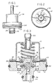
- Fig. 1 is an elevational view through a fuel pressure regulator embodying the invention;
- Fig. 2 is a sectional view transversely to the longitudinal axis;
- Fig. 3 is a fragmentary view on an enlarged scale of the main portions of the fuel pressure regulator shown in Fig. 1;
- Fig. 4 is a sectional view on an enlarged scale of a modified form of fuel pressure regulator.
- Referring to Fig. 1, the fuel pressure regulator embodying the invention comprises a
housing 10 consisting of twohalves 11, 12 that are clamped together by foldingflange 13 overflange 14. Adiaphragm 15 is provided between thehousing halves 11, 12 and may be made of two layers of elastic material such as fabric reinforced fluoro-silicone. Thediaphragm 15 divides the housing into afirst chamber 16 and asecond chamber 17. A clampingfiberboard spacer 18 is interposed between theflanges diaphragm 15. Thediaphragm 15 supports acarrier 19 and thecarrier 19 is held in position by aspring retainer 20 that is connected to thecarrier 19 by staking. Acompression spring 21 urges theretainer 20 and cage 19 downwardly as shown in Fig. 3. Thechamber 16 includes a passage orvacuum fitting 22.Housing half 12 includes a plurality ofinlet openings 23 to thechamber 17 and includes anintegral projection 24 having anaxial passage 25 extending upwardly adjacent the diaphragm and defining a frustoconical seat 26. - The
carrier 19 supports aplate 28 that has an opening 29 therein. Avalve 30 has a hollow tubular closedend portion 31 that projects through the opening 29 in theplate 28 for engagement with the valve seat 27. Valve 30 includes a planarperipheral portion 32 which extends radially outwardly from saidtubular portion 31 and retains thevalve 30 between thecarrier 19 and theplate 28. Asecond light spring 33 is interposed between thecarrier 19 and extends into thetubular portion 31 of thevalve 30 to yieldingly urge thevalve portion 31 toward the valve seat 27 while permitting relative movement between thevalve 30 and the valve seat 27. The diameter of the opening 29 is greater than the outer diameter of thetubular portion 31 ofvalve 30 so that thevalve 30 can move laterally permitting movement of the valve to accommodate any misalignment between thetubular portion 31 and valve seat 27. -
Annular seals housing half 12.Seal 36 is positioned within a groove of thehousing half 12 where such half is of larger diameter than at theintegral projection 24 where thehousing half 12 is of smaller diameter and has another groove for receiving theseal 36.Seal 35 isolates theinlet openings 23 from the atmosphere and seal 36 isolates theinlet openings 23 from theoutlet openings 25. - In operation, when the ignition is turned on, fuel is introduced by the fuel pump to
inlets 23 and forces the diaphragm upwardly permitting fuel to flow through thepassage 25 out of the regulator through outlet opening 25 to the fuel tank. As manifold vacuum of the engine changes, the vacuum applied tovacuum passage 22 causes the diaphragm to move thevalve 31 away from or closer to the seat 26 and the amount of fluid passing through the outlet is changed, maintaining a constant pressure differential across the injectors. - In the modified form shown in Fig. 4, provision is made for greater flow by having the annular seat 26 of greater diameter. A
valve 30a has aflange 32a which engagesplate 28 to retainvalve 30a. Valve 30a includes a groove 32b in the plane ofplate 28 to permit relative lateral movement ofvalve 30a such that a portion of the plate extends into the groove 32b. - It can thus be seen that the present invention provides a fuel pressure regulator of the type shown in the aforementioned United States Patent 4,627,463 which is more compact, easier to assemble and less costly to manufacture.
Claims (5)
a diaphragm (15) dividing the housing (10) into a first chamber (16) and a second chamber (17),
a passage (22) from the exterior of the housing (10) to said first chamber (16),
an inlet (23) and an outlet (25) associated with the second chamber (17) of the housing (10),
a valve seat (26) associated with the outlet (25),
a carrier (19) mounted on and movable with the diaphragm (15),
a spring (21) within the first chamber (16) yieldingly urging the carrier (19) toward the valve seat (26),
said carrier (19) supporting a plate (28) that has an opening (29) therein,
a valve (30, 30a) for engagement with said valve seat (26),
means retaining said valve (30, 30a) between said carrier (19) and said plate (28),
a second spring (33, 33a) interposed between said carrier (19) and said valve (30) to yieldingly urge same toward the valve seat (26) and permit relative movement between said valve (30, 30a) and said valve seat (26),
characterized in that
said valve (30) comprises a hollow tubular closed end portion (31, 31a) that projects through said opening (29) in the plate (28),
said retaining means is shaped as a peripheral portion (32, 32a) of said valve (30, 30a) and
said second spring (33, 33a) extends into the tubular portion (31, 31a) of the valve (30, 30a) and engages said closed end tubular portion (31, 31a).
Applications Claiming Priority (2)
| Application Number | Priority Date | Filing Date | Title |
|---|---|---|---|
| US95643 | 1979-11-19 | ||
| US07/095,643 US4741360A (en) | 1987-09-14 | 1987-09-14 | Fuel pressure regulator |
Publications (2)
| Publication Number | Publication Date |
|---|---|
| EP0307532A2 true EP0307532A2 (en) | 1989-03-22 |
| EP0307532A3 EP0307532A3 (en) | 1990-10-17 |
Family
ID=22252937
Family Applications (1)
| Application Number | Title | Priority Date | Filing Date |
|---|---|---|---|
| EP19880101296 Withdrawn EP0307532A3 (en) | 1987-09-14 | 1988-01-29 | Fuel pressure regulator |
Country Status (4)
| Country | Link |
|---|---|
| US (1) | US4741360A (en) |
| EP (1) | EP0307532A3 (en) |
| JP (1) | JP2582106B2 (en) |
| CA (1) | CA1286946C (en) |
Cited By (1)
| Publication number | Priority date | Publication date | Assignee | Title |
|---|---|---|---|---|
| DE4119431A1 (en) * | 1991-06-13 | 1992-12-17 | Brumme Kg Effbe Werk | PRESSURE REGULATOR |
Families Citing this family (23)
| Publication number | Priority date | Publication date | Assignee | Title |
|---|---|---|---|---|
| JP2985471B2 (en) * | 1992-02-04 | 1999-11-29 | 株式会社デンソー | Fuel pressure regulator |
| US5220941A (en) * | 1992-06-02 | 1993-06-22 | Walbro Corporation | Fuel pressure regulator |
| US5265644A (en) * | 1992-06-02 | 1993-11-30 | Walbro Corporation | Fuel pressure regulator |
| JP2557799B2 (en) * | 1993-12-29 | 1996-11-27 | 京三電機株式会社 | Pressure control valve |
| US5509444A (en) * | 1995-03-30 | 1996-04-23 | Siemens Automotive Corporation | Flow through pressure regulator |
| US6056009A (en) * | 1995-06-05 | 2000-05-02 | Ford Motor Company | Fluid pressure regulator |
| US5673670A (en) * | 1995-07-05 | 1997-10-07 | Ford Motor Company | Returnless fuel delivery system |
| DE19616512C1 (en) * | 1996-04-25 | 1997-09-11 | Brumme Kg Effbe Werk | Pressure valve |
| US5709369A (en) * | 1996-07-05 | 1998-01-20 | Fisher Controls International, Inc. | Self-aligning valve disc assembly |
| US5857486A (en) * | 1996-09-24 | 1999-01-12 | 1219737 Ontario Inc. | Pressure relief or back pressure valve |
| DE10012904B4 (en) * | 2000-03-16 | 2004-08-12 | Lewa Herbert Ott Gmbh + Co | Membrane clamping with elasticity compensation |
| MXPA03000437A (en) * | 2000-07-31 | 2003-10-06 | Leggitt S H Co | Bonnet securement for gas pressure regulators. |
| US6748964B2 (en) | 2001-08-03 | 2004-06-15 | Siemens Automotive Corporation | Flow-through pressure regulator self-contained valve assembly |
| US6629543B2 (en) | 2001-08-03 | 2003-10-07 | Siemens Automotive Corporation | Fuel system including a self-contained flow-through pressure regulator |
| US6886590B2 (en) * | 2002-09-20 | 2005-05-03 | Siemens Vdo Automative Corporation | Seal assembly for fuel pressure regulator |
| US7866339B2 (en) * | 2004-10-01 | 2011-01-11 | Siemens Aktiengesellschaft | Pressure regulator for a fuel supply unit |
| JP2007333171A (en) * | 2006-06-19 | 2007-12-27 | Ben:Kk | Trap device |
| US20080053535A1 (en) * | 2006-08-30 | 2008-03-06 | Leggitt Don C | Cylinder valve regulator |
| US7775235B2 (en) * | 2007-05-31 | 2010-08-17 | Synerject, Llc | Apparatus and methods for containing a fuel pressure regulator |
| US20120174995A1 (en) * | 2011-01-06 | 2012-07-12 | Shane Bloomer | Low Pressure / High Flow Back Pressure Device and System |
| US9346075B2 (en) * | 2011-08-26 | 2016-05-24 | Nordson Corporation | Modular jetting devices |
| US9671029B2 (en) * | 2015-09-26 | 2017-06-06 | Te-Feng Lin | Lid of gas pressure regulator |
| ES2733448T3 (en) * | 2016-01-04 | 2019-11-29 | Danfoss As | Capsule for a valve and valve |
Family Cites Families (7)
| Publication number | Priority date | Publication date | Assignee | Title |
|---|---|---|---|---|
| US2062857A (en) * | 1934-03-01 | 1936-12-01 | Fedders Mfg Co Inc | Refrigerant control device |
| US2311110A (en) * | 1940-12-09 | 1943-02-16 | Roy W Johnson | Valve |
| US4231347A (en) * | 1977-12-19 | 1980-11-04 | Aisin Seiki Kabushiki Kaisha | Fuel pressure regulating valve |
| US4237924A (en) * | 1978-12-05 | 1980-12-09 | Schmelzer Corporation | Fuel pressure regulator |
| US4357921A (en) * | 1981-06-11 | 1982-11-09 | Weber Carburatori Azienda Della Weber S.P.A. | Pressure regulator for injection systems for spark ignition internal combustion engines |
| US4624442A (en) * | 1985-01-23 | 1986-11-25 | Duffy John W | Control regulator having a rolling diaphragm |
| US4627463A (en) * | 1985-04-11 | 1986-12-09 | Tom Mcguane Industries, Inc. | Fuel pressure regulator |
-
1987
- 1987-09-14 US US07/095,643 patent/US4741360A/en not_active Expired - Lifetime
-
1988
- 1988-01-18 CA CA 556729 patent/CA1286946C/en not_active Expired - Fee Related
- 1988-01-29 EP EP19880101296 patent/EP0307532A3/en not_active Withdrawn
- 1988-02-03 JP JP2365488A patent/JP2582106B2/en not_active Expired - Lifetime
Cited By (1)
| Publication number | Priority date | Publication date | Assignee | Title |
|---|---|---|---|---|
| DE4119431A1 (en) * | 1991-06-13 | 1992-12-17 | Brumme Kg Effbe Werk | PRESSURE REGULATOR |
Also Published As
| Publication number | Publication date |
|---|---|
| JP2582106B2 (en) | 1997-02-19 |
| JPH0192572A (en) | 1989-04-11 |
| EP0307532A3 (en) | 1990-10-17 |
| CA1286946C (en) | 1991-07-30 |
| US4741360A (en) | 1988-05-03 |
Similar Documents
| Publication | Publication Date | Title |
|---|---|---|
| EP0307532A2 (en) | Fuel pressure regulator | |
| EP0198381B1 (en) | Fuel pressure regulator | |
| KR100351572B1 (en) | Non-return fuel system for fuel pressure vacuum reaction | |
| KR100300740B1 (en) | Pressure regulating valve and fuel supply device using it | |
| US4552311A (en) | Low cost unitized fuel injection system | |
| US4310142A (en) | Fuel pressure regulator assembly | |
| WO2005031201A1 (en) | Pressure regulator assembly | |
| JP2002180907A (en) | Vehicle fuel gas supply system | |
| EP0817991B1 (en) | Flow through pressure regulator | |
| US5979409A (en) | Integral returnless pressure regulator for a fuel injection system | |
| US6293259B1 (en) | Automotive fuel system having a pressure regulator without a movable diaphragm | |
| US4633901A (en) | Pressure regulator | |
| US6481418B1 (en) | Fuel pressure regulator | |
| US5193576A (en) | Pressure regulator | |
| EP0166528A2 (en) | Fuel pressure regulator | |
| EP0747593A3 (en) | Fluid pressure regulator | |
| KR970008665B1 (en) | Pressure control device | |
| GB2307517A (en) | Exhaust gas recirculation (EGR) valve with integral servo vacuum valve | |
| US20200347811A1 (en) | Fuel pressure regulator | |
| US4903667A (en) | Pressure regulating valve | |
| US7040344B2 (en) | Pressure regulator including a fixed valve ball and method of assembling the same | |
| US6629543B2 (en) | Fuel system including a self-contained flow-through pressure regulator | |
| US20030056769A1 (en) | Fuel pressure regulator assembly for fuel delivery module | |
| US7063104B2 (en) | Flow-through pressure regulator including a closure member assembly integrated with a housing | |
| JPH0118834Y2 (en) |
Legal Events
| Date | Code | Title | Description |
|---|---|---|---|
| PUAI | Public reference made under article 153(3) epc to a published international application that has entered the european phase |
Free format text: ORIGINAL CODE: 0009012 |
|
| AK | Designated contracting states |
Kind code of ref document: A2 Designated state(s): DE FR GB IT |
|
| PUAL | Search report despatched |
Free format text: ORIGINAL CODE: 0009013 |
|
| AK | Designated contracting states |
Kind code of ref document: A3 Designated state(s): DE FR GB IT |
|
| 17P | Request for examination filed |
Effective date: 19901222 |
|
| 17Q | First examination report despatched |
Effective date: 19920901 |
|
| STAA | Information on the status of an ep patent application or granted ep patent |
Free format text: STATUS: THE APPLICATION IS DEEMED TO BE WITHDRAWN |
|
| 18D | Application deemed to be withdrawn |
Effective date: 19930112 |