EP0307033B1 - Stützrahmen für Abdeckelemente in Zwischenwänden oder dergleichen - Google Patents
Stützrahmen für Abdeckelemente in Zwischenwänden oder dergleichen Download PDFInfo
- Publication number
- EP0307033B1 EP0307033B1 EP88201847A EP88201847A EP0307033B1 EP 0307033 B1 EP0307033 B1 EP 0307033B1 EP 88201847 A EP88201847 A EP 88201847A EP 88201847 A EP88201847 A EP 88201847A EP 0307033 B1 EP0307033 B1 EP 0307033B1
- Authority
- EP
- European Patent Office
- Prior art keywords
- frame
- profiles
- profile
- load
- arms
- Prior art date
- Legal status (The legal status is an assumption and is not a legal conclusion. Google has not performed a legal analysis and makes no representation as to the accuracy of the status listed.)
- Expired
Links
- 239000002184 metal Substances 0.000 claims description 30
- 239000000463 material Substances 0.000 claims description 9
- 230000002093 peripheral effect Effects 0.000 claims description 5
- 230000008878 coupling Effects 0.000 claims description 3
- 238000010168 coupling process Methods 0.000 claims description 3
- 238000005859 coupling reaction Methods 0.000 claims description 3
- 239000002991 molded plastic Substances 0.000 claims description 3
- 239000004033 plastic Substances 0.000 claims description 3
- 229920003023 plastic Polymers 0.000 claims description 3
- 230000005489 elastic deformation Effects 0.000 claims description 2
- 238000003825 pressing Methods 0.000 claims description 2
- 230000015572 biosynthetic process Effects 0.000 claims 1
- 238000005192 partition Methods 0.000 description 6
- 239000011521 glass Substances 0.000 description 5
- 210000002105 tongue Anatomy 0.000 description 4
- 238000005520 cutting process Methods 0.000 description 2
- 239000000428 dust Substances 0.000 description 2
- 230000037431 insertion Effects 0.000 description 2
- 238000003780 insertion Methods 0.000 description 2
- 229910001234 light alloy Inorganic materials 0.000 description 2
- 238000005452 bending Methods 0.000 description 1
- 230000008859 change Effects 0.000 description 1
- 238000004140 cleaning Methods 0.000 description 1
- 238000010276 construction Methods 0.000 description 1
- 238000009432 framing Methods 0.000 description 1
- 238000009413 insulation Methods 0.000 description 1
- 238000004519 manufacturing process Methods 0.000 description 1
- 238000002360 preparation method Methods 0.000 description 1
- 230000002787 reinforcement Effects 0.000 description 1
- 230000000284 resting effect Effects 0.000 description 1
- 238000007789 sealing Methods 0.000 description 1
- 238000000638 solvent extraction Methods 0.000 description 1
- 239000012780 transparent material Substances 0.000 description 1
- 238000009966 trimming Methods 0.000 description 1
Images


Classifications
-
- E—FIXED CONSTRUCTIONS
- E06—DOORS, WINDOWS, SHUTTERS, OR ROLLER BLINDS IN GENERAL; LADDERS
- E06B—FIXED OR MOVABLE CLOSURES FOR OPENINGS IN BUILDINGS, VEHICLES, FENCES OR LIKE ENCLOSURES IN GENERAL, e.g. DOORS, WINDOWS, BLINDS, GATES
- E06B3/00—Window sashes, door leaves, or like elements for closing wall or like openings; Layout of fixed or moving closures, e.g. windows in wall or like openings; Features of rigidly-mounted outer frames relating to the mounting of wing frames
- E06B3/96—Corner joints or edge joints for windows, doors, or the like frames or wings
- E06B3/964—Corner joints or edge joints for windows, doors, or the like frames or wings using separate connection pieces, e.g. T-connection pieces
- E06B3/9647—Corner joints or edge joints for windows, doors, or the like frames or wings using separate connection pieces, e.g. T-connection pieces the connecting piece being part of or otherwise linked to the window or door fittings
- E06B3/9648—Mitre joints
-
- E—FIXED CONSTRUCTIONS
- E04—BUILDING
- E04B—GENERAL BUILDING CONSTRUCTIONS; WALLS, e.g. PARTITIONS; ROOFS; FLOORS; CEILINGS; INSULATION OR OTHER PROTECTION OF BUILDINGS
- E04B2/00—Walls, e.g. partitions, for buildings; Wall construction with regard to insulation; Connections specially adapted to walls
- E04B2/74—Removable non-load-bearing partitions; Partitions with a free upper edge
-
- E—FIXED CONSTRUCTIONS
- E06—DOORS, WINDOWS, SHUTTERS, OR ROLLER BLINDS IN GENERAL; LADDERS
- E06B—FIXED OR MOVABLE CLOSURES FOR OPENINGS IN BUILDINGS, VEHICLES, FENCES OR LIKE ENCLOSURES IN GENERAL, e.g. DOORS, WINDOWS, BLINDS, GATES
- E06B3/00—Window sashes, door leaves, or like elements for closing wall or like openings; Layout of fixed or moving closures, e.g. windows in wall or like openings; Features of rigidly-mounted outer frames relating to the mounting of wing frames
- E06B3/96—Corner joints or edge joints for windows, doors, or the like frames or wings
- E06B3/964—Corner joints or edge joints for windows, doors, or the like frames or wings using separate connection pieces, e.g. T-connection pieces
- E06B3/968—Corner joints or edge joints for windows, doors, or the like frames or wings using separate connection pieces, e.g. T-connection pieces characterised by the way the connecting pieces are fixed in or on the frame members
- E06B3/9681—Corner joints or edge joints for windows, doors, or the like frames or wings using separate connection pieces, e.g. T-connection pieces characterised by the way the connecting pieces are fixed in or on the frame members by press fit or adhesion
- E06B3/9682—Mitre joints
Definitions
- the subject of the present invention is a load-bearing frame for closure elements, for example transparent elements, in internal dividing walls and the like.
- Such internal dividing walls are usually constructed of a unit-composed structure, for the purpose of enabling them to be brought into use at any time after construction of the fixed walling of the room in which they are placed and easy dismantling if the internal subdivision is to be shifted or modified.
- Walls of this class must have particular characteristics, among these to provide effective insulation against noise, dust and so on, and they must be capable of accommodating doors, transparent elements, openings or other features, as well as carrying brackets or possessing a sufficient thickness to receive shelves and the like, constituting not only a wall but also a container.
- the support frames for the transparent elements or elements of other type either opaque or translucent, adapted for closing the bays formed by the load-bearing grid of the wall, which require a frame for their support, both for functional reasons and for reasons of peripheral finishing or trimming; said frames make up the main frame, to which is secured the closure element, for example composed of a plate of transparent material such as glass.
- the pane-holding frames moreover, in general have the characteristic of being composed of a plurality of rectilinear segments, mounted at angles to one another, equipped with joint elements at the corners and with sealing profiles or gaskets for securing the plate of glass or similar material: the preparation and assembly of such components proves to be a complex operation, difficult to carry out automatically, which therefore influence the overall cost of the product.
- US-A-2989788 discloses a load bearing frame according to the first portion of claim 1 and providing joints which are hold in place by friction of barbs laterally bent: this structure, due to the lateral flexibility of these barbs and to the play between the remaining part of the joint and the framings, cannot assure a complete rigidity; since the holding in place of the joints is only granted by friction it cannot prevent a loosening of the joint.
- BE-A-735446 deals about a gasket to hold in place the panels, but these gaskets too are not suitable to hold in place panels of different thickness.
- pane holding frame which shall offer the best possible characteristics of rigidity, combined with the aesthetic requirements of small bulk and of the parts that are externally visible, which shall moreover be especially rapid to assemble, with a reduced number of operations and limited tools necessary for the manual operations, thus offering a reduced cost of production.
- elastic clamping means comprising teeth elastically insertable in corresponding recesses of the metal profiles, said throat portions of the metal profiles being adapted for seating a gasket for securing a closure plate, which possesses a portion of U section of rigid plastics material and at least one flexible lip facing towards the interior of the U section, the lip being adapted for elastically pressing a plate of small or large thickness inserted into the gasket.
- the metal profiles are composed of a tubular portion, having a principal part of substantially square cross-section and a secondary part, oriented towards the outside of the frame formed of the profiles, having a quadrangular shape contiguous to the principal part, from which secondary part there projects, also outwardly form the frame and in its part, facing towards the front, a throat shaped limb, possessing associated retaining portions, forming the fixity seating for a gasket for securing the closure plate, there being also present a flat limb, extending towards the rear part of the frame, and adapted for concealing the members for securing the frame to the wall.
- the securing gasket for the closure plate is inserted fixedly into the corresponding throat of the metal profile before said profile is cut to length for forming the frame, the gasket being cut together with the metal profile in a single operation.
- the shaped joints that can be inserted into the tubular parts of the metal profiles for securing the profiles at an angle to form the frame are composed of an L-shaped body having equal, perpendicular arms, with a substantially square cross-section, the arms being adapted to be inserted into the part of square cross-section of the tubular portion of the profile, from which there projects outwards a peripheral limb, adapted to be inserted into the secondary part of the tubular portion of the metal profile,for the purpose of increasing the flexural rigidity of the joint, transverse projections being present on the arms of the body of the joint, adapted to be inserted into the tubular part of the profile with elastic deformation, securing the joint by friction to the metal profiles pushed onto it, there being also present curved elastic hook elements, projecting beyond the profile of the body of the joint, in correspondence with which there are present recesses in the metal profiles, into which the elastic elements are inserted, when the joint is inserted into position in the corresponding tubular part of the metal profiles.
- the recesses of the metal profiles are in a position that determines the insertion into them of the elastic hook elements in conditions of clamping, the one onto the other, of the converging metal profiles fitted onto the arms of the joint.
- the elements for concealing the members for securing the frame to the structure of the wall, and/or the load-bearing structure itself of the wall comprise a metal frame composed of a shaped profile having a tubular portion and a limb for connecting to the structure, there being present corner joints, adapted for connecting the profiles of the frame, which can be inserted into the tubular portions of the profiles.
- the corner joints are formed of an L-shaped element of shaped plastics material, having arms that can be inserted by force into the seatings of two converging, mutually perpendicular profiles, the arms being secured by friction in them, the L-shaped member being equipped, in addition, on the arm that is orientated vertically, with a tongue carrying a projecting pin, adapted for engaging into a corresponding hole of the uprights and cross-members of the structure, thus carrying the weight of the concealing frame.
- a dividing wall or partition extends between a pair of mutually facing walls 1, a floor 2 and a ceiling 3, for the purpose of separating two parts of a room of larger dimensions.
- the dividing wall substantially comprises a peripheral frame 4, secured to said walls 1, floor 2 and ceiling 3, to which there are connected a plurality of uprights 5 carrying respective cross-members 6, defining bays of various dimensions, in which there are disposed wall panels 7, of the opaque type and closure elements 8, for example transparent, doors 9 and the like.
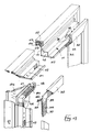
- the closure elements 8 are composed of a "pane-holding" frame 10, constructed of an extruded light alloy profile 11, the shape of which can be seen more clearly in section in Figures 2, 3, and in the exploded view of Figure 4.
- the profile 11 possesses a central tubular portion, comprising a zone of substantially square section 12 and a rectangular zone 13, of smaller thickness, facing outwardly from the quadrilateral formed of the four profile segments making up the frame adapted for carrying a closure plate, for example of glass or the like; into said tubular portion, as shown in Fig. 4, at the ends of the profiles 11 cut to length with a 45° mitre to form the corners of the frame, there is inserted an angle joint 14, of moulded plastics material, by means of which the connection of the mutually perpendicular profiles of said frame is effected.
- Said joint comprises an angled body having a substantially square section 15, adapted to be inserted into the zone 12 of the profile 11, and a peripheral limb 16, adapted to be inserted into the zone 13 of the tubular part of the profile 11; the extension of the limb 16 assures to the joint the bending stiffness necessary for guaranteeing perpendicularity between the contiguous profiles 11 connected by it.
- the surface of the body 15 of the joint possesses projections 17, adapted for permitting the joint to be inserted with friction into the zone 12 of the profile 11, thus facilitating the holding of this joint in its seating; the securing of the profile 11 to the joint 14 is furthermore assured by the end portions of the arms of the joint itself, possessing at their ends a raised elastic tooth 18, projecting, as shown in Figure 6, from the surface of the body 15, in correspondence with which tooth a recess 19 is formed in the profile 11; in this manner, the profiles 11 can be fitted onto the joint with an elastic force fit, until blockage is obtained by the emergence of the tooth 18 from the recess 19, as can be seen in Figure 4; this assures rigidity of the connection, by keeping the coupling surfaces, mitred at 45°, of the profiles 11 clamped elastically onto each other, and assembly may be carried out in an especially rapid manner without the use of special equipment, in particular without the use of screws.
- the profiles 11 have a seating 22, adapted for housing a gasket or seal 23, substantially of U-section, into which there is inserted a closure plate 24, for example a transparent plate, of glass or the like.
- the gasket 23 possesses a flexible lip 25 and a corresponding raised flange 26, appropriately formed of a material that is elastically more deformable than the remaining part of the gasket; said lip 25, and partly also the raised flange 26, as shown in Figure 2 in its right-hand and left-hand parts respectively, can deflect to a lesser or greater extent towards the interior of the profile of the gasket, so that it is possible to receive, without change of gasket, either plates 24a of small thickness, for example 3 mm, or plates 24b of greater thickness, for example 7 mm.
- the gasket 23 is designed to be inserted into the respective seating 22 before the profiles 11 are cut to length, by using automatic machines to operate on entire bars comprising profiles 11 and gaskets 23; during assembly, the cutting to size of the profiles 11 and of the associated pane-fixing gaskets takes place in one single operation, thus providing a considerable saving in time, both as a result of the possibility of automating the fitting of the gasket to the profile, and as a result of the simultaneous cutting to dimensions of the profile and the gasket, thereby achieving higher accuracy in execution.
- the arrangement of the seating 22 and of the gasket 23, the flexible lip of which is disposed, as shown in the Figures, towards the inside, also enables the external surface of the closure plate to be kept substantially flush with the remaining part of the surface of the wall, with associated advantages in respect of aesthetics and cleaning, thereby avoiding the presence of re-entrant angles at the support frame for the transparent plates, where dust and the like could accumulate.
- the shape of the profile 11 allows the closure plate to be secured in the vicinity of the perimeter of the frame which supports it, keeping the remaining part of the frame, the size of which is determined by the requirements for providing adequate stiffness to the whole assembly, in a position that is more internal and set back with respect to the closure plate, with consequent aesthetic improvements.
- Said support and assembly members are, for example, constituted of respective hooks 28, secured by means of screws or the like to the profiles 11 forming the vertical faces of the frame 10, by means of which said frame is secured to bolts 29 projecting from the uprights; as Figure 2 shows, after the frame has been mounted in position, said hook elements or other similar elements are no longer visible, being entirely obscured by the limbs 27.
- the pane-holding frame is equipped with corresponding members for fixing to the uprights, for example in the form of angles 30 resting on associated pins 31 of said uprights; in such a case, for the purpose of concealing the fixing members from view, an auxiliary covering frame 32 is provided, extending from the limb 27 of the profile 11 of the pane-holding frame opposite the surface of cross-beams and uprights.
- Said covering frame 32 is composed of profiles of light alloy or similar material, the form of which in cross-section is shown in Figures 3 and 4 and is composed of a quadrilateral portion 33, having its larger dimension in the plane of the frame, which extends towards the limb 27 with an associated connecting limb 34.
- connection of the profile segments constituting the frame the use is provided of a corner joint 35, of moulded plastics material, by means of which the connection together of the mutually perpendicular profiles of said frame is achieved.
- Said joint shown more clearly in Figures 7, 8 and 9, has an angled body having a substantially rectangular section 36, adapted to be inserted into the quadrilateral portion 33 of the profile of the frame; the surface of the body 36 of the joint possesses projections 37, adapted for allowing it to be inserted with friction into the portion 33, thereby ensuring holding by friction; in this manner, assembly may be carried out in an especially rapid manner and without the use of special tools, in particular without the use of screws or other retaining elements.
- the quadrilateral portion 33 of the profile of the frame 32 possesses an aperture 38, and in correspondence therewith the joint 35 possesses a longitudinal projection 39; from this projection 39 there extends a shaped tongue 40, equipped with a projecting pin 41, which moreover projects outside the frame 32.
- the tongue 40 is present on only one of the two mutually perpendicular arms of the body of the joint 35, in particular on the arm intended to be mounted vertically in the frame.
- the pins 41 are provided for insertion into corresponding holes of the adjacent uprights, in this manner supporting the self-weight of the frame 32; said holes may be formed for this purpose on the uprights or, preferably, they are constituted of the same holes provided along the edges of the uprights for seating support pins and the like for the cross-members, for the pane-holding frames, for shelves and the like, as illustrated in Figure 3, or they may be constituted of analogous fixing members, to which the tongues 40 and pins 41 are shaped to correspond.
Landscapes
- Engineering & Computer Science (AREA)
- Civil Engineering (AREA)
- Structural Engineering (AREA)
- Architecture (AREA)
- Physics & Mathematics (AREA)
- Electromagnetism (AREA)
- Securing Of Glass Panes Or The Like (AREA)
Claims (8)
Applications Claiming Priority (2)
| Application Number | Priority Date | Filing Date | Title |
|---|---|---|---|
| IT8721787A IT1222584B (it) | 1987-09-03 | 1987-09-03 | Cornice portante per elementi di chiusura in pareti divisorie interne e simili |
| IT2178787 | 1987-09-03 |
Publications (2)
| Publication Number | Publication Date |
|---|---|
| EP0307033A1 EP0307033A1 (de) | 1989-03-15 |
| EP0307033B1 true EP0307033B1 (de) | 1992-02-05 |
Family
ID=11186843
Family Applications (1)
| Application Number | Title | Priority Date | Filing Date |
|---|---|---|---|
| EP88201847A Expired EP0307033B1 (de) | 1987-09-03 | 1988-08-30 | Stützrahmen für Abdeckelemente in Zwischenwänden oder dergleichen |
Country Status (3)
| Country | Link |
|---|---|
| EP (1) | EP0307033B1 (de) |
| ES (1) | ES2028993T3 (de) |
| IT (1) | IT1222584B (de) |
Family Cites Families (11)
| Publication number | Priority date | Publication date | Assignee | Title |
|---|---|---|---|---|
| US2966967A (en) * | 1956-08-14 | 1961-01-03 | Reflector Hardware Corp | Wall construction |
| US2989788A (en) * | 1959-03-09 | 1961-06-27 | Kessler Milton | Corner key for screen frames and the like |
| CH386663A (de) * | 1960-05-06 | 1965-01-15 | Luethi Hans | Bauelement für Trennwände |
| FR1309059A (fr) * | 1962-01-02 | 1962-11-09 | Profilés métalliques pour la réalisation de châssis de fenêtre | |
| US3162282A (en) * | 1963-02-25 | 1964-12-22 | Harvey Window Inc | Window bracket |
| CH492094A (de) * | 1968-01-20 | 1970-06-15 | Lust Kg Ernst | Trennwand |
| BE735446A (de) * | 1969-07-01 | 1969-12-16 | ||
| FR2422020A1 (fr) * | 1978-04-07 | 1979-11-02 | Damas Lucien | Porte et son procede de fabrication |
| DE2900693C2 (de) * | 1979-01-10 | 1982-08-19 | Top - element Bauelemente für Innenausbau + Raumgestaltung GmbH & Co KG, 4700 Hamm | Vorrichtung zum Verbinden von zwei zueinander rechtwinklig angeordneten, stumpf gestoßenen Zargenschenkeln, insbesondere für Fensterzargen |
| WO1984002559A1 (fr) * | 1982-12-29 | 1984-07-05 | Japan Art Kikaku Co Ltd | Dispositif de couplage pour cadre façonne |
| DE3308233A1 (de) * | 1983-03-09 | 1984-09-13 | Weinmann KG, 7295 Dornstetten | Rahmenwerk mit zwischen dessen rahmenelementen einzufuegenden einsatzteilen |
-
1987
- 1987-09-03 IT IT8721787A patent/IT1222584B/it active
-
1988
- 1988-08-30 EP EP88201847A patent/EP0307033B1/de not_active Expired
- 1988-08-30 ES ES198888201847T patent/ES2028993T3/es not_active Expired - Lifetime
Also Published As
| Publication number | Publication date |
|---|---|
| ES2028993T3 (es) | 1992-07-16 |
| IT8721787A0 (it) | 1987-09-03 |
| IT1222584B (it) | 1990-09-05 |
| EP0307033A1 (de) | 1989-03-15 |
Similar Documents
| Publication | Publication Date | Title |
|---|---|---|
| US6058667A (en) | Modular window for partition panels | |
| US6988344B1 (en) | Modular wall structural elements, and methods of using same | |
| US4567698A (en) | Space divider system | |
| US4569171A (en) | Base trim system for partition corners | |
| US5024030A (en) | Space divider system | |
| US4787184A (en) | Door and window frame | |
| CA2068506C (en) | Pre-assembled glazed panel with trim assembly for wall panel systems | |
| US3509673A (en) | Modular partition wall system | |
| US6513288B1 (en) | Window assembly for partitions | |
| CA2051707A1 (en) | Molding of synthetic resin foam with hidden fittings | |
| JPH023865B2 (de) | ||
| US5655344A (en) | Framework of partition walls | |
| US4949520A (en) | Modular componential system for assembling various building interior facade structures | |
| US4223967A (en) | Telescopic structural element for making modular closets, partition walls, door supports and the like | |
| US4437285A (en) | Building structure | |
| EP0307033B1 (de) | Stützrahmen für Abdeckelemente in Zwischenwänden oder dergleichen | |
| US4984403A (en) | Modular building block | |
| RU2213832C2 (ru) | Способ построения офисных перегородок | |
| EP0309033B1 (de) | Containerförmige modulare interne Trennwand | |
| GB2209063A (en) | Fastener for panels | |
| JPH0497048A (ja) | 化粧パネルの取付構造 | |
| EP0735208A2 (de) | Bauwerk mit modularen Wänden | |
| EP0818861A1 (de) | Dichte Tür für Schränke elektrischer Einheiten | |
| JPH0135912Y2 (de) | ||
| KR100191351B1 (ko) | 달반자 구조 |
Legal Events
| Date | Code | Title | Description |
|---|---|---|---|
| PUAI | Public reference made under article 153(3) epc to a published international application that has entered the european phase |
Free format text: ORIGINAL CODE: 0009012 |
|
| AK | Designated contracting states |
Kind code of ref document: A1 Designated state(s): ES FR GB IT |
|
| 17P | Request for examination filed |
Effective date: 19890408 |
|
| 17Q | First examination report despatched |
Effective date: 19900124 |
|
| GRAA | (expected) grant |
Free format text: ORIGINAL CODE: 0009210 |
|
| AK | Designated contracting states |
Kind code of ref document: B1 Designated state(s): ES FR GB IT |
|
| ET | Fr: translation filed | ||
| ITF | It: translation for a ep patent filed | ||
| REG | Reference to a national code |
Ref country code: ES Ref legal event code: FG2A Ref document number: 2028993 Country of ref document: ES Kind code of ref document: T3 |
|
| PLBE | No opposition filed within time limit |
Free format text: ORIGINAL CODE: 0009261 |
|
| STAA | Information on the status of an ep patent application or granted ep patent |
Free format text: STATUS: NO OPPOSITION FILED WITHIN TIME LIMIT |
|
| 26N | No opposition filed | ||
| PGFP | Annual fee paid to national office [announced via postgrant information from national office to epo] |
Ref country code: GB Payment date: 19950803 Year of fee payment: 8 |
|
| PGFP | Annual fee paid to national office [announced via postgrant information from national office to epo] |
Ref country code: FR Payment date: 19950804 Year of fee payment: 8 |
|
| PGFP | Annual fee paid to national office [announced via postgrant information from national office to epo] |
Ref country code: ES Payment date: 19950810 Year of fee payment: 8 |
|
| PG25 | Lapsed in a contracting state [announced via postgrant information from national office to epo] |
Ref country code: GB Effective date: 19960830 |
|
| PG25 | Lapsed in a contracting state [announced via postgrant information from national office to epo] |
Ref country code: ES Free format text: LAPSE BECAUSE OF EXPIRATION OF PROTECTION Effective date: 19960831 |
|
| GBPC | Gb: european patent ceased through non-payment of renewal fee |
Effective date: 19960830 |
|
| PG25 | Lapsed in a contracting state [announced via postgrant information from national office to epo] |
Ref country code: FR Effective date: 19970430 |
|
| REG | Reference to a national code |
Ref country code: FR Ref legal event code: ST |
|
| REG | Reference to a national code |
Ref country code: ES Ref legal event code: FD2A Effective date: 19990601 |
|
| PG25 | Lapsed in a contracting state [announced via postgrant information from national office to epo] |
Ref country code: IT Free format text: LAPSE BECAUSE OF NON-PAYMENT OF DUE FEES;WARNING: LAPSES OF ITALIAN PATENTS WITH EFFECTIVE DATE BEFORE 2007 MAY HAVE OCCURRED AT ANY TIME BEFORE 2007. THE CORRECT EFFECTIVE DATE MAY BE DIFFERENT FROM THE ONE RECORDED. Effective date: 20050830 |