EP0307030A1 - Tube chauffant - Google Patents
Tube chauffant Download PDFInfo
- Publication number
- EP0307030A1 EP0307030A1 EP88201831A EP88201831A EP0307030A1 EP 0307030 A1 EP0307030 A1 EP 0307030A1 EP 88201831 A EP88201831 A EP 88201831A EP 88201831 A EP88201831 A EP 88201831A EP 0307030 A1 EP0307030 A1 EP 0307030A1
- Authority
- EP
- European Patent Office
- Prior art keywords
- region
- heating pipe
- cross
- section
- heating
- Prior art date
- Legal status (The legal status is an assumption and is not a legal conclusion. Google has not performed a legal analysis and makes no representation as to the accuracy of the status listed.)
- Granted
Links
Images
Classifications
-
- A—HUMAN NECESSITIES
- A01—AGRICULTURE; FORESTRY; ANIMAL HUSBANDRY; HUNTING; TRAPPING; FISHING
- A01G—HORTICULTURE; CULTIVATION OF VEGETABLES, FLOWERS, RICE, FRUIT, VINES, HOPS OR SEAWEED; FORESTRY; WATERING
- A01G9/00—Cultivation in receptacles, forcing-frames or greenhouses; Edging for beds, lawn or the like
- A01G9/24—Devices or systems for heating, ventilating, regulating temperature, illuminating, or watering, in greenhouses, forcing-frames, or the like
- A01G9/245—Conduits for heating by means of liquids, e.g. used as frame members or for soil heating
-
- F—MECHANICAL ENGINEERING; LIGHTING; HEATING; WEAPONS; BLASTING
- F28—HEAT EXCHANGE IN GENERAL
- F28F—DETAILS OF HEAT-EXCHANGE AND HEAT-TRANSFER APPARATUS, OF GENERAL APPLICATION
- F28F1/00—Tubular elements; Assemblies of tubular elements
- F28F1/02—Tubular elements of cross-section which is non-circular
-
- F—MECHANICAL ENGINEERING; LIGHTING; HEATING; WEAPONS; BLASTING
- F28—HEAT EXCHANGE IN GENERAL
- F28F—DETAILS OF HEAT-EXCHANGE AND HEAT-TRANSFER APPARATUS, OF GENERAL APPLICATION
- F28F1/00—Tubular elements; Assemblies of tubular elements
- F28F1/10—Tubular elements and assemblies thereof with means for increasing heat-transfer area, e.g. with fins, with projections, with recesses
- F28F1/12—Tubular elements and assemblies thereof with means for increasing heat-transfer area, e.g. with fins, with projections, with recesses the means being only outside the tubular element
- F28F1/14—Tubular elements and assemblies thereof with means for increasing heat-transfer area, e.g. with fins, with projections, with recesses the means being only outside the tubular element and extending longitudinally
- F28F1/16—Tubular elements and assemblies thereof with means for increasing heat-transfer area, e.g. with fins, with projections, with recesses the means being only outside the tubular element and extending longitudinally the means being integral with the element, e.g. formed by extrusion
-
- F—MECHANICAL ENGINEERING; LIGHTING; HEATING; WEAPONS; BLASTING
- F28—HEAT EXCHANGE IN GENERAL
- F28D—HEAT-EXCHANGE APPARATUS, NOT PROVIDED FOR IN ANOTHER SUBCLASS, IN WHICH THE HEAT-EXCHANGE MEDIA DO NOT COME INTO DIRECT CONTACT
- F28D21/00—Heat-exchange apparatus not covered by any of the groups F28D1/00 - F28D20/00
- F28D2021/0019—Other heat exchangers for particular applications; Heat exchange systems not otherwise provided for
- F28D2021/0035—Other heat exchangers for particular applications; Heat exchange systems not otherwise provided for for domestic or space heating, e.g. heating radiators
-
- Y—GENERAL TAGGING OF NEW TECHNOLOGICAL DEVELOPMENTS; GENERAL TAGGING OF CROSS-SECTIONAL TECHNOLOGIES SPANNING OVER SEVERAL SECTIONS OF THE IPC; TECHNICAL SUBJECTS COVERED BY FORMER USPC CROSS-REFERENCE ART COLLECTIONS [XRACs] AND DIGESTS
- Y02—TECHNOLOGIES OR APPLICATIONS FOR MITIGATION OR ADAPTATION AGAINST CLIMATE CHANGE
- Y02A—TECHNOLOGIES FOR ADAPTATION TO CLIMATE CHANGE
- Y02A40/00—Adaptation technologies in agriculture, forestry, livestock or agroalimentary production
- Y02A40/10—Adaptation technologies in agriculture, forestry, livestock or agroalimentary production in agriculture
- Y02A40/25—Greenhouse technology, e.g. cooling systems therefor
Definitions
- This invention relates to a heating pipe for emitting heat supplied by means of a fluid passed therethrough.
- Heating pipes of this type are employed e.g. in greenhouses for cultivating plants.
- Generally known for this purpose are heating pipes having a substantially circular cross-section, with the diameter of such heating pipes being tuned to the required heating area.
- a drawback of such a heating pipe is its relatively large water content, resulting in a slow reaction of the system when heat is required or, on the other hand, no heat is required any more.
- the first case occurs e.g. at sunset, so that the temperature in a greenhouse may decrease quite rapidly. Such a temperature decrease can be detected quickly by means of a thermostat, which subsequently switches on the heating system.
- too much time may have been lost for optimal growth conditions.
- a triangular heating pipe for instance can be deemed to be considerably less suitable for that purpose than a circular one.
- a pipe which is characterized in that, as viewed in cross-section, it has a wall which defines at least two contiguous regions, distinct as regards their form, a first region having a large length relative to its width and longitudinally adjoining a second region having a width, i.e. the largest dimension thereof perpendicular to the longitudinal direction of the first region, larger than the width of the first region, while the ratio between the cross-sectional area and the length of the boundary thereof formed by the wall, is smaller for the first region than for the second region.
- the second region adjoining the first is integral with the first but can be designed largely independently of the first region, so that the second region may have a cross-sectional area to provide for flow properties as favourable as possible and without dead zones wherein sediment can collect.
- the relatively large heating area relative to the sectional area available for fluid flow has the advantage that the heating system can react relatively quickly in on/off situations, while, moreover, a minimal amount of water need be heated, so that when the system is turned off, only a minimal amount of heat is used ineffectively.
- the heating pipe should generally be installed with the second region underneath the first, so that particles settling in the first region fall towards the second region, where sediment is prevented from collecting and accumulating due to the flow conditions prevailing therein.
- the first region will extend more or less vertically upwards and thus be suitable for use as a guiding and carrying rail. It will be clear that the first region can have a form which is suitable therefor without further ado.
- a further, additional advantage of the relatively small water content of the heating pipe according to the present invention is that the weight of the total heating pipe network becomes appreciably lower, which has constructional advantages.
- the second region may have various forms. In accordance with a further embodiment of the present invention, however, the second region has a substantially circular cross-section.
- Such a design of the second region has the further, additional advantage that the connecting pipe between the heating pipe and the distribution pipes, which, as it is, has a smaller diameter than the known heating pipes of circular cross-section, may be an extension of the second region, so that no special provisions are required for the transition between the heating pipe and the inlet or outlet pipe.
- the transition between the first and the second regions is substantially stepped.
- this leads to a particular preference for a substantially keyhole-shaped cross-section, while in view of the above discussion in connection with the arrangement of the heating pipe, the pipe will in actual practice be inverted-keyhole-shaped in cross-section.
- the manufacture of such a heating pipe can be effected in any desired, known manner, e.g. by extrusion, welding, deformation and the like.
- the starting point may be a pipe of circular cross-section on which the hollow fin or rib is rolled by deformation.
- the longitudinal walls of the first region converge from the second region and that, as viewed in cross-section, the wall near the transition between the first and the second regions has a radius convex towards the inside, which is advantageous from the viewpoint of flow engineering as well.
- the first region Due to the design of the first region as a hollow fin or rib, and the arrangement of the heating pipe with that hollow fin or rib in substantially vertically upward direction, not only is a favourable discharge of sediment effected but likewise an advantageous venting possibility is obtained. In fact any air present in the heating medium will rise and collect at the top of the hollow fin or rib, which effect will be reinforced by the low flow velocity of the heating medium near the top end of the hollow fin or rib.
- local provisions have been made at the end of the first area remote from the second area for installing venting means.
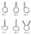
- Fig. 1 is a cross-sectional view of a heating pipe consisting of two distinct, contiguous wall regions; a first region 1 in the form of a hollow fin or rib and a second region 2 having a substantially circular cross-section.
- the heating pipe is shown in the position in which it is preferably arranged in practice, i.e. with the first region 1 extending vertically upwards from the second region 2.
- the main stream will pass through the circular, second region 2.
- the flow rate will be lower, viz.
- the rather narrow first region 1 will be fed with hot medium, with the heat being transmitted quickly and effectively to the surrounding space to be heated, as a result of the fin or rib form.
- Due to the design and the arrangement of the heating pipe sediment can nowhere collect and accumulate in the heating pipe, for such collections and accumulations can only occur in areas of low or no flow velocity.
- An area of this kind is present in the heating pipe shown in Fig. 1, but is located in the top end of the first region 1. Sediment cannot collect there but will fall into the first region 1 at the maximum flow velocity.
- the high position of the region with low or no flow velocity has the additional advantage of offering ideal conditions for collecting and discharging air from the heating medium. To that effect venting means can be provided in a simple manner near the top end of the first region 1.
- the diameter of the second region 2 is equal to that of the inlet or outlet tube, while the first region 1 is suitably closed at its end.
- the top end of the first region 1 can be used as a guiding and carrying rail for a transport means without more ado. If desired, the top end of the first portion, to that effect, may have any desired configuration deviating from the round shape shown in the figure.
- Figs. 2-6 show further possible forms of the heating pipe, it being explicitly understood that these do not concern an exhaustive enumeration of all possibilities.
- the cross-sectional profile of the heating pipe shown in Fig. 2 deviates from that shown in Fig. 1 by the configuration of the walls of the first portion converging from the second portion.
- a similar configuration can be realized in a comparatively simple manner by deformation of a circular pipe having a circumference equal to that of the heating pipe shown in Fig. 2.
- the first portion links up tangentially, instead of radially, with the second portion.
- the top of the second portion could be considered to use the top of the second portion as a guiding and carrying rail for a transport means.
- the second portion has a substantially C-shaped cross-section, while that of Fig. 5 has an elliptical cross-section.
- Fig. 6 finally, shows two first portions 1 mutually enclosing an angle and linking up substantially radially with the second portion.
- This embodiment true, has a larger water content than the above discussed embodiments, but also a substantially larger heating area.
- the heating pipe can be made by deformation of a pipe having a circular cross-section. Naturally, a different cross-section may form the starting point, while other manufacturing methods, such as extrusion or welding, may be employed.
Priority Applications (1)
| Application Number | Priority Date | Filing Date | Title |
|---|---|---|---|
| AT88201831T ATE69103T1 (de) | 1987-08-28 | 1988-08-26 | Heizungsrohr. |
Applications Claiming Priority (2)
| Application Number | Priority Date | Filing Date | Title |
|---|---|---|---|
| NL8702021 | 1987-08-28 | ||
| NL8702021A NL8702021A (nl) | 1987-08-28 | 1987-08-28 | Verwarmingsbuis. |
Publications (2)
| Publication Number | Publication Date |
|---|---|
| EP0307030A1 true EP0307030A1 (fr) | 1989-03-15 |
| EP0307030B1 EP0307030B1 (fr) | 1991-10-30 |
Family
ID=19850515
Family Applications (1)
| Application Number | Title | Priority Date | Filing Date |
|---|---|---|---|
| EP88201831A Expired - Lifetime EP0307030B1 (fr) | 1987-08-28 | 1988-08-26 | Tube chauffant |
Country Status (4)
| Country | Link |
|---|---|
| EP (1) | EP0307030B1 (fr) |
| AT (1) | ATE69103T1 (fr) |
| DE (1) | DE3865935D1 (fr) |
| NL (1) | NL8702021A (fr) |
Cited By (3)
| Publication number | Priority date | Publication date | Assignee | Title |
|---|---|---|---|---|
| EP1235039A2 (fr) * | 2001-02-23 | 2002-08-28 | Metech S.r.l. | Echangeur de chaleur à spirale constitué d'un élément tubulaire à section en forme de goutte |
| WO2010062185A1 (fr) * | 2008-11-17 | 2010-06-03 | Bioforsk | Appareil et procédé pour la régulation de température d'un milieu de culture dans une serre et utilisation de ceux-ci pour la lutte contre des organismes pathogènes pour les plantes |
| CN112944973A (zh) * | 2021-03-30 | 2021-06-11 | 中国农业大学 | 翅片式水体换热器及养殖池系统 |
Citations (6)
| Publication number | Priority date | Publication date | Assignee | Title |
|---|---|---|---|---|
| FR436317A (fr) * | 1911-11-08 | 1912-03-25 | Gay Et Bourgoens Soc | Radiateur pour automobiles et autres applications |
| US1558205A (en) * | 1924-04-03 | 1925-10-20 | Siefken Otto | Automobile radiator |
| US1608204A (en) * | 1924-09-26 | 1926-11-23 | Charles B Foster | Heating coil |
| US1874009A (en) * | 1930-05-28 | 1932-08-30 | John J Nesbitt Inc | Expanded tube radiator |
| FR2385023A1 (fr) * | 1977-03-23 | 1978-10-20 | Michel Albert | Tube metallique de grande resistance specifique pour echafaudage ou autres et materiel construit avec ledit tube |
| FR2445213A2 (fr) * | 1978-12-29 | 1980-07-25 | Akzo Nv | Tube a paroi mince en polymere extrudable pour dispositif de transfert de chaleur |
-
1987
- 1987-08-28 NL NL8702021A patent/NL8702021A/nl not_active Application Discontinuation
-
1988
- 1988-08-26 AT AT88201831T patent/ATE69103T1/de not_active IP Right Cessation
- 1988-08-26 DE DE8888201831T patent/DE3865935D1/de not_active Expired - Lifetime
- 1988-08-26 EP EP88201831A patent/EP0307030B1/fr not_active Expired - Lifetime
Patent Citations (6)
| Publication number | Priority date | Publication date | Assignee | Title |
|---|---|---|---|---|
| FR436317A (fr) * | 1911-11-08 | 1912-03-25 | Gay Et Bourgoens Soc | Radiateur pour automobiles et autres applications |
| US1558205A (en) * | 1924-04-03 | 1925-10-20 | Siefken Otto | Automobile radiator |
| US1608204A (en) * | 1924-09-26 | 1926-11-23 | Charles B Foster | Heating coil |
| US1874009A (en) * | 1930-05-28 | 1932-08-30 | John J Nesbitt Inc | Expanded tube radiator |
| FR2385023A1 (fr) * | 1977-03-23 | 1978-10-20 | Michel Albert | Tube metallique de grande resistance specifique pour echafaudage ou autres et materiel construit avec ledit tube |
| FR2445213A2 (fr) * | 1978-12-29 | 1980-07-25 | Akzo Nv | Tube a paroi mince en polymere extrudable pour dispositif de transfert de chaleur |
Cited By (4)
| Publication number | Priority date | Publication date | Assignee | Title |
|---|---|---|---|---|
| EP1235039A2 (fr) * | 2001-02-23 | 2002-08-28 | Metech S.r.l. | Echangeur de chaleur à spirale constitué d'un élément tubulaire à section en forme de goutte |
| EP1235039A3 (fr) * | 2001-02-23 | 2004-03-03 | Metech S.r.l. | Echangeur de chaleur à spirale constitué d'un élément tubulaire à section en forme de goutte |
| WO2010062185A1 (fr) * | 2008-11-17 | 2010-06-03 | Bioforsk | Appareil et procédé pour la régulation de température d'un milieu de culture dans une serre et utilisation de ceux-ci pour la lutte contre des organismes pathogènes pour les plantes |
| CN112944973A (zh) * | 2021-03-30 | 2021-06-11 | 中国农业大学 | 翅片式水体换热器及养殖池系统 |
Also Published As
| Publication number | Publication date |
|---|---|
| NL8702021A (nl) | 1989-03-16 |
| DE3865935D1 (de) | 1991-12-05 |
| ATE69103T1 (de) | 1991-11-15 |
| EP0307030B1 (fr) | 1991-10-30 |
Similar Documents
| Publication | Publication Date | Title |
|---|---|---|
| EP0617245B1 (fr) | Inhibiteur des dépÔts calcaires intégré | |
| EP0307030A1 (fr) | Tube chauffant | |
| CN2690831Y (zh) | 一种蒸发式冷凝冷却器 | |
| US5988117A (en) | Top inlet for a water heater | |
| CN110425903A (zh) | 一种翅片式换热器及其智能调温方法 | |
| CN101782300B (zh) | 一种热交换器 | |
| WO1998020280A1 (fr) | Procede applicable avec un generateur de vapeur en continu, et le generateur de vapeur necessaire a l'application de ce procede | |
| KR20010012354A (ko) | 밸브 장치를 가열하기 위한 방법 및 장치 | |
| DE202009011326U1 (de) | Wärmetauscher für den Rauchgaskanal einer Feuerung | |
| CN214039043U (zh) | 一种微通道换热器和空调系统 | |
| CA2239007C (fr) | Raccord d'admission pour chauffe-eau | |
| CN108733954B (zh) | 蒸汽管网的配置方法 | |
| KR19990076766A (ko) | 나선형으로 배치된 증발관을 갖춘 연속 흐름 증기 발생기 | |
| CN220521004U (zh) | 道路排水结构 | |
| CN219951313U (zh) | 一种自动排气的液相热媒散热装置 | |
| US1950774A (en) | Hydraulic turbine | |
| CN111964305B (zh) | 一种二氧化碳热泵 | |
| JPH10339595A (ja) | 熱交換器 | |
| CN218001683U (zh) | 除湿板改进的除湿器 | |
| CN208671352U (zh) | 一种整体式加热器 | |
| US6431461B1 (en) | Tapered air purging circulator | |
| CA2575965C (fr) | Raccord d'admission pour chauffe-eau | |
| CN216845863U (zh) | 一种可自调节液位的换热器结构 | |
| CN2438985Y (zh) | 太阳能热水器 | |
| CN201715782U (zh) | 变通道气液分离式换热器 |
Legal Events
| Date | Code | Title | Description |
|---|---|---|---|
| PUAI | Public reference made under article 153(3) epc to a published international application that has entered the european phase |
Free format text: ORIGINAL CODE: 0009012 |
|
| AK | Designated contracting states |
Kind code of ref document: A1 Designated state(s): AT BE CH DE FR GB IT LI LU NL |
|
| 17P | Request for examination filed |
Effective date: 19890202 |
|
| RAP3 | Party data changed (applicant data changed or rights of an application transferred) |
Owner name: TREUR, TEUNIS JAN |
|
| 17Q | First examination report despatched |
Effective date: 19900131 |
|
| GRAA | (expected) grant |
Free format text: ORIGINAL CODE: 0009210 |
|
| AK | Designated contracting states |
Kind code of ref document: B1 Designated state(s): AT BE CH DE FR GB IT LI LU NL |
|
| REF | Corresponds to: |
Ref document number: 69103 Country of ref document: AT Date of ref document: 19911115 Kind code of ref document: T |
|
| REF | Corresponds to: |
Ref document number: 3865935 Country of ref document: DE Date of ref document: 19911205 |
|
| ITF | It: translation for a ep patent filed |
Owner name: SOCIETA' ITALIANA BREVETTI S.P.A. |
|
| ET | Fr: translation filed | ||
| PLBE | No opposition filed within time limit |
Free format text: ORIGINAL CODE: 0009261 |
|
| STAA | Information on the status of an ep patent application or granted ep patent |
Free format text: STATUS: NO OPPOSITION FILED WITHIN TIME LIMIT |
|
| 26N | No opposition filed | ||
| EPTA | Lu: last paid annual fee | ||
| PGFP | Annual fee paid to national office [announced via postgrant information from national office to epo] |
Ref country code: LU Payment date: 19940801 Year of fee payment: 7 |
|
| PGFP | Annual fee paid to national office [announced via postgrant information from national office to epo] |
Ref country code: GB Payment date: 19940826 Year of fee payment: 7 |
|
| PGFP | Annual fee paid to national office [announced via postgrant information from national office to epo] |
Ref country code: BE Payment date: 19940829 Year of fee payment: 7 |
|
| PGFP | Annual fee paid to national office [announced via postgrant information from national office to epo] |
Ref country code: FR Payment date: 19940902 Year of fee payment: 7 |
|
| PG25 | Lapsed in a contracting state [announced via postgrant information from national office to epo] |
Ref country code: LU Free format text: LAPSE BECAUSE OF NON-PAYMENT OF DUE FEES Effective date: 19950826 Ref country code: GB Effective date: 19950826 |
|
| PG25 | Lapsed in a contracting state [announced via postgrant information from national office to epo] |
Ref country code: BE Effective date: 19950831 |
|
| BERE | Be: lapsed |
Owner name: TREUR TEUNIS JAN Effective date: 19950831 |
|
| GBPC | Gb: european patent ceased through non-payment of renewal fee |
Effective date: 19950826 |
|
| PG25 | Lapsed in a contracting state [announced via postgrant information from national office to epo] |
Ref country code: FR Effective date: 19960430 |
|
| REG | Reference to a national code |
Ref country code: FR Ref legal event code: ST |
|
| PGFP | Annual fee paid to national office [announced via postgrant information from national office to epo] |
Ref country code: AT Payment date: 19980831 Year of fee payment: 11 |
|
| PGFP | Annual fee paid to national office [announced via postgrant information from national office to epo] |
Ref country code: CH Payment date: 19980902 Year of fee payment: 11 |
|
| PGFP | Annual fee paid to national office [announced via postgrant information from national office to epo] |
Ref country code: DE Payment date: 19980930 Year of fee payment: 11 |
|
| PG25 | Lapsed in a contracting state [announced via postgrant information from national office to epo] |
Ref country code: AT Free format text: LAPSE BECAUSE OF NON-PAYMENT OF DUE FEES Effective date: 19990826 |
|
| PG25 | Lapsed in a contracting state [announced via postgrant information from national office to epo] |
Ref country code: LI Free format text: LAPSE BECAUSE OF NON-PAYMENT OF DUE FEES Effective date: 19990831 Ref country code: CH Free format text: LAPSE BECAUSE OF NON-PAYMENT OF DUE FEES Effective date: 19990831 |
|
| REG | Reference to a national code |
Ref country code: CH Ref legal event code: PL |
|
| PG25 | Lapsed in a contracting state [announced via postgrant information from national office to epo] |
Ref country code: DE Free format text: LAPSE BECAUSE OF NON-PAYMENT OF DUE FEES Effective date: 20000601 |
|
| PGFP | Annual fee paid to national office [announced via postgrant information from national office to epo] |
Ref country code: NL Payment date: 20040831 Year of fee payment: 17 |
|
| PG25 | Lapsed in a contracting state [announced via postgrant information from national office to epo] |
Ref country code: IT Free format text: LAPSE BECAUSE OF NON-PAYMENT OF DUE FEES Effective date: 20050826 |
|
| PG25 | Lapsed in a contracting state [announced via postgrant information from national office to epo] |
Ref country code: NL Free format text: LAPSE BECAUSE OF NON-PAYMENT OF DUE FEES Effective date: 20060301 |
|
| NLV4 | Nl: lapsed or anulled due to non-payment of the annual fee |
Effective date: 20060301 |