EP0306744A2 - Tibial component of a knee joint endoprosthesis - Google Patents
Tibial component of a knee joint endoprosthesis Download PDFInfo
- Publication number
- EP0306744A2 EP0306744A2 EP88113468A EP88113468A EP0306744A2 EP 0306744 A2 EP0306744 A2 EP 0306744A2 EP 88113468 A EP88113468 A EP 88113468A EP 88113468 A EP88113468 A EP 88113468A EP 0306744 A2 EP0306744 A2 EP 0306744A2
- Authority
- EP
- European Patent Office
- Prior art keywords
- shells
- plateaus
- bridge
- tibial
- side walls
- Prior art date
- Legal status (The legal status is an assumption and is not a legal conclusion. Google has not performed a legal analysis and makes no representation as to the accuracy of the status listed.)
- Granted
Links
Images
Classifications
-
- A—HUMAN NECESSITIES
- A61—MEDICAL OR VETERINARY SCIENCE; HYGIENE
- A61F—FILTERS IMPLANTABLE INTO BLOOD VESSELS; PROSTHESES; DEVICES PROVIDING PATENCY TO, OR PREVENTING COLLAPSING OF, TUBULAR STRUCTURES OF THE BODY, e.g. STENTS; ORTHOPAEDIC, NURSING OR CONTRACEPTIVE DEVICES; FOMENTATION; TREATMENT OR PROTECTION OF EYES OR EARS; BANDAGES, DRESSINGS OR ABSORBENT PADS; FIRST-AID KITS
- A61F2/00—Filters implantable into blood vessels; Prostheses, i.e. artificial substitutes or replacements for parts of the body; Appliances for connecting them with the body; Devices providing patency to, or preventing collapsing of, tubular structures of the body, e.g. stents
- A61F2/02—Prostheses implantable into the body
- A61F2/30—Joints
- A61F2/38—Joints for elbows or knees
- A61F2/389—Tibial components
Definitions
- the invention relates to a tibia part of a knee joint endoprosthesis according to the preamble of claim 1.
- tibia parts are e.g. known from DE-C 34 33 264.
- the object of the invention is to significantly facilitate the replacement of worn plateaus by new plateaus in tibia parts of the type mentioned above, but to ensure a proper fixation of the plateaus in the metallic shells.
- the clamp consists of a rectangular sheet metal, one leg of which is supported on the top of the bridge and which has arms provided laterally with outwardly directed pins and the other leg with a clamping incision via a pin of the bridge directed into the space between the two shells takes hold.
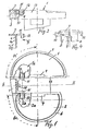
- the tibia part of the knee joint endoprosthesis consists of the two metallic shells 1 and 2, which are connected at the front by a bridge 3.
- Plastic tibial plateaus 1a, 2a are inserted into the shells 1, 2, on which the runners of a femoral part slide, a fixing projection 4 of the shell walls 13 engaging in a corresponding, facing recess in the plateaus 1a, 2a.
- the tibial plateaus 1a, 2a are only partially shown in Fig.1.
- the side wall 5, 6 of the two shells 1, 2 is lowered in the front curved part over the length 5a, 6a in height relative to the other side wall, so that the plateaus 1a, 2a are then pushed into the shells from the front and worn out Conversely, plateaus can be removed from the shells.
- a fixing clamp is used to compensate for this.
- This clamp consists of a rectangular sheet metal, one leg 7 of which is supported on the surface of the bridge 3 and the other leg 8 is provided with a central upright incision 9 and with this incision 9 via a pin 10 directed into the space between the two shells the bridge 3 is pressed and thereby pushes the two surface halves of the leg 8 apart until the pin 10 engages or snaps into the extension 9a of the incision 9.
- the terminal is now firmly and detachably connected to the bridge.
- the upper leg 7 of the clamp has an arm 11 on each side, at the ends of which a fixing pin 12 is fastened, that protrudes into the area of the shells 1, 2.
- the parallel shell side walls 13 and the tibial plateaus 1a, 2a are provided with upper incisions 14, 24 in the region of the pins 12, and accordingly the two tibial plateaus 1a, 2a to be inserted into the shells 1,2 are provided with upper recesses 1b 2b into which insert the pins 12 and thereby fix the two plateaus 1a, 2a in their shells 1, 2.
Abstract
Description
Die Erfindung geht aus von einem Tibiateil einer Kniegelenk-Endoprothese nach dem Oberbegriff des Anspruches 1. Derartige Tibiateile sind z.B. durch die DE-C 34 33 264 bekannt.The invention relates to a tibia part of a knee joint endoprosthesis according to the preamble of
Bei den vorerwähnten bekannten Tibiateilen ist es möglich, die Tibiaplateaus aus einem geeigneten Kunststoff nach einem Verschleiß auszutauschen, während die vorn überbrückten metallischen Schalen im Schienbein verankert bleiben. Es hat sich herausgestellt, daß dieser Plateauaustausch verhältnismäßig schwierig durchzuführen ist, da die Plateaus von den Seitenwandungen der metallischen Schalen eingefaßt sind und daher ein weites Auseinanderspreizen der beiden Gelenkteile eines Patienten erfordern, um die verschlissenen Plateaus herauszunehmen und die neuen Plateaus wieder einsetzen zu können.In the known tibia parts mentioned above, it is possible to replace the tibia plateaus from a suitable plastic after wear, while the metallic shells bridged at the front remain anchored in the shin. It has been found that this plateau exchange is relatively difficult to carry out, since the plateaus are bordered by the side walls of the metallic shells and therefore require the two joint parts of a patient to be widely spread apart in order to be able to remove the worn plateaus and to reinsert the new plateaus.
Die Aufgabe der Erfindung besteht darin, bei Tibiateilen der eingangs erwähnten Art den Austausch verschlissener durch neue Plateaus wesentlich zu erleichtern, dabei aber eine einwandfreie Fixierung der Plateaus in den metallischen Schalen zu gewährleisten.The object of the invention is to significantly facilitate the replacement of worn plateaus by new plateaus in tibia parts of the type mentioned above, but to ensure a proper fixation of the plateaus in the metallic shells.
Diese Aufgabe wird nach der Erfindung durch die kennzeichnenden Merkmale des Anspruches 1 gelöst.This object is achieved according to the invention by the characterizing features of
Durch diese Lösung ist es möglich, die Plateaus von vorn in die Schalen einzuschieben, wobei der Vorsprung der beiden parallelen Wandungen in die entsprechenden Ausnehmungen der Plateaus in bekannter Weise einfassen. Dabei wird die durch die Höhenverringerung der vorderen Schalenwandungen verschlechterte Fixierung der Plateaus dadurch wieder ausgeglichen und verbessert, daß die Klemme vorgesehen ist, die sich beim Aufsetzen auf die Brücke der beiden Schalen mit der Brücke lösbar verbindet und mit den quergerichteten Zapfen in obere seitliche Ausnehmungen der Plateaus eingreift und die Plateaus damit in ihrer Lage in den Schalen sichert.This solution makes it possible to push the plateaus into the shells from the front, the projection of the two parallel walls encompassing the corresponding recesses in the plateaus in a known manner. The deterioration of the height of the front shell walls fixation of the plateaus is compensated for and improved by the fact that the clamp is provided which releasably connects to the bridge when it is placed on the bridge of the two shells and with the transverse pin in the upper lateral recesses of the Engages plateaus and thus secures the position of the plateaus in the shells.
Vorteilhaft besteht die Klemme aus einem rechtwinkligen Blech, dessen einer Schenkel sich oben auf der Brücke abstützt und das seitlich mit nach außen gerichteten Zapfen versehene Arme aufweist und dessen anderer Schenkel mit einem klemmenden Einschnitt über einen in den Freiraum zwischen den beiden Schalen gerichteten Zapfen der Brücke greift.Advantageously, the clamp consists of a rectangular sheet metal, one leg of which is supported on the top of the bridge and which has arms provided laterally with outwardly directed pins and the other leg with a clamping incision via a pin of the bridge directed into the space between the two shells takes hold.
Die Erfindung wird nachstehend anhand der Zeichnung erläutert. Es zeigt:
Figur 1 eine Aufsicht auf den Tibiateil einer Kniegelenk-Endoprothese mit der Klemme nach der Erfindung,- Figur einen Schnitt nach der Linie II-II der
Figur 1 Figur 3 die Klemme nachFigur 2, getrennt von dem Tibiateil dargestellt,Figur 4 eine Ansicht der Klemme in Richtung des Pfeiles IV derFigur 3.
- FIG. 1 shows a top view of the tibia part of a knee joint endoprosthesis with the clamp according to the invention,
- Figure a section along the line II-II of Figure 1
- FIG. 3 shows the clamp according to FIG. 2, shown separately from the tibia part,
- Figure 4 is a view of the clamp in the direction of arrow IV of Figure 3.
Das Tibiateil der Kniegelenk-Endoprothese besteht aus den beiden metallischen Schalen 1 und 2, die vorn durch eine Brücke 3 verbunden sind. In die Schalen 1,2 werden Tibiaplateaus 1a, 2a aus Kunststoff eingesetzt, auf denen die Kufen eines Femurteiles gleiten, wobei ein Fixiervorsprung 4 der Schalenwandungen 13 in eine entsprechende zugekehrte Ausnehmung der Plateaus 1a,2a eingreift. Die Tibiaplateaus 1a,2a sind in Fig.1 nur zum Teil dargestellt.The tibia part of the knee joint endoprosthesis consists of the two
Gemäß der Erfindung ist die Seitenwand 5,6 der beiden Schalen 1, 2 im vorderen gebogenen Teil auf der Länge 5a, 6a in der Höhe gegenüber der sonstigen Seitenwand herabgesetzt, so daß dann die Plateaus 1a, 2a von vorn in die Schalen eingeschoben und verschlissene Plateaus umgekehrt aus den Schalen herausgenommen werden können.According to the invention, the side wall 5, 6 of the two
Durch die herabgesetzte Höhe der Seitenwandungen 5a,6a wird die Fixierung der Plateaus 1a, 2a in den Schalen etwas ungünstig beeinflußt. Um dies auszugleichen, kommt eine Fixierklemme zur Anwendung. Diese Klemme besteht aus einem rechtwinkligen Blech, dessen einer Schenkel 7 sich auf der Oberfläche der Brücke 3 abstützt und dessen anderer Schenkel 8 mit einem mittigen aufrechten Einschnitt 9 versehen ist und mit diesem Einschnitt 9 über einen in den Freiraum zwischen den beiden Schalen gerichteten Zapfen 10 der Brücke 3 gedrückt wird und dabei die beiden Flächenhälften des Schenkels 8 auseinanderdrückt, bis der Zapfen 10 in die Erweiterung 9a des Einschnittes 9 eingreift bzw. einschnappt. Damit ist die Klemme fest und lösbar mit der Brücke verbunden.Due to the reduced height of the side walls 5a, 6a, the fixation of the
Der obere Schenkel 7 der Klemme besitzt seitlich je einen Arm 11, an deren Enden je ein Fixierzapfen 12 befestigt ist, der in den Bereich der Schalen 1,2 hineinragt. Dabei sind die parallelen Schalenseitenwandungen 13 und die Tibiaplateaus 1a, 2a im Bereich der Zapfen 12 mit oberen Einschnitten 14, 24 versehen, und entsprechend sind die beiden in die Schalen 1,2 einzuschiebenden Tibiaplateaus 1a, 2a mit oberen Ausnehumgen 1b 2b versehen, in die sich die Zapfen 12 einlegen und dadurch die beiden Plateaus 1a, 2a in ihren Schalen 1,2 fixieren.The
Claims (2)
Priority Applications (1)
| Application Number | Priority Date | Filing Date | Title |
|---|---|---|---|
| AT88113468T ATE75388T1 (en) | 1987-09-09 | 1988-08-19 | TIBIAL PART OF A KNEE ARTHROTHESES. |
Applications Claiming Priority (2)
| Application Number | Priority Date | Filing Date | Title |
|---|---|---|---|
| DE3730175A DE3730175C1 (en) | 1987-09-09 | 1987-09-09 | Tibial part of a knee joint endoprosthesis |
| DE3730175 | 1987-09-09 |
Publications (3)
| Publication Number | Publication Date |
|---|---|
| EP0306744A2 true EP0306744A2 (en) | 1989-03-15 |
| EP0306744A3 EP0306744A3 (en) | 1989-12-06 |
| EP0306744B1 EP0306744B1 (en) | 1992-04-29 |
Family
ID=6335553
Family Applications (1)
| Application Number | Title | Priority Date | Filing Date |
|---|---|---|---|
| EP88113468A Expired - Lifetime EP0306744B1 (en) | 1987-09-09 | 1988-08-19 | Tibial component of a knee joint endoprosthesis |
Country Status (3)
| Country | Link |
|---|---|
| EP (1) | EP0306744B1 (en) |
| AT (1) | ATE75388T1 (en) |
| DE (2) | DE3730175C1 (en) |
Cited By (9)
| Publication number | Priority date | Publication date | Assignee | Title |
|---|---|---|---|---|
| EP0672397A1 (en) * | 1994-03-15 | 1995-09-20 | Allo Pro Ag | Tibial plate for an artificial knee joint |
| EP0855172A3 (en) * | 1997-01-17 | 1998-12-30 | CeramTec AG Innovative Ceramic Engineering | Fastening of a tibial piece on a tibilal tray of a knee prosthesis |
| US8529631B2 (en) | 2008-07-18 | 2013-09-10 | Zimmer, Gmbh | Base component for a tibial implant |
| US8911501B2 (en) | 2011-12-29 | 2014-12-16 | Mako Surgical Corp. | Cruciate-retaining tibial prosthesis |
| US9198762B2 (en) | 2011-01-10 | 2015-12-01 | Howmedica Osteonics Corp. | Bicruciate retaining tibial baseplate |
| US9345578B2 (en) | 2013-02-22 | 2016-05-24 | Stryker Corporation | Bicruciate retaining tibial implant system |
| US9668871B2 (en) | 2011-12-29 | 2017-06-06 | Mako Surgical Corp. | Cruciate-retaining tibial prosthesis |
| US10231840B2 (en) | 2016-07-27 | 2019-03-19 | Howmedica Osteonics Corp. | Low profile tibial baseplate with fixation members |
| US10413415B2 (en) | 2010-09-10 | 2019-09-17 | Zimmer, Inc. | Motion facilitating tibial components for a knee prosthesis |
Families Citing this family (14)
| Publication number | Priority date | Publication date | Assignee | Title |
|---|---|---|---|---|
| DE59707850D1 (en) * | 1997-01-10 | 2002-09-05 | Sulzer Orthopaedie Ag Baar | Tibial platform for an artificial knee joint |
| EP1252870A1 (en) * | 2001-04-25 | 2002-10-30 | Waldemar Link (GmbH & Co.) | Knee prosthesis with a bending hinge |
| EP2595574B1 (en) | 2010-07-24 | 2017-05-03 | Zimmer, Inc. | Asymmetric tibial components for a knee prosthesis |
| US8764840B2 (en) | 2010-07-24 | 2014-07-01 | Zimmer, Inc. | Tibial prosthesis |
| US8603101B2 (en) | 2010-12-17 | 2013-12-10 | Zimmer, Inc. | Provisional tibial prosthesis system |
| EP3848005A3 (en) | 2011-11-18 | 2021-09-15 | Zimmer, Inc. | Tibial bearing component for a knee prosthesis with improved articular characteristics |
| AU2012341026B2 (en) | 2011-11-21 | 2015-01-29 | Zimmer, Inc. | Tibial baseplate with asymmetric placement of fixation structures |
| IN2014DN07145A (en) | 2012-01-30 | 2015-04-24 | Zimmer Inc | |
| US9925052B2 (en) | 2013-08-30 | 2018-03-27 | Zimmer, Inc. | Method for optimizing implant designs |
| EP3352708B1 (en) | 2015-09-21 | 2020-07-22 | Zimmer, Inc. | Prosthesis system including tibial bearing component |
| ES2878003T3 (en) | 2017-03-10 | 2021-11-18 | Zimmer Inc | Tibial prosthesis with locking feature for a tibial bearing component |
| AU2018266322B2 (en) | 2017-05-12 | 2020-03-19 | Zimmer, Inc. | Femoral prostheses with upsizing and downsizing capabilities |
| US11426282B2 (en) | 2017-11-16 | 2022-08-30 | Zimmer, Inc. | Implants for adding joint inclination to a knee arthroplasty |
| US10835380B2 (en) | 2018-04-30 | 2020-11-17 | Zimmer, Inc. | Posterior stabilized prosthesis system |
Citations (2)
| Publication number | Priority date | Publication date | Assignee | Title |
|---|---|---|---|---|
| US4353136A (en) * | 1980-11-05 | 1982-10-12 | Polyzoides Apostolos J | Endoprosthetic knee joint |
| EP0177776A2 (en) * | 1984-09-11 | 1986-04-16 | S + G Implants Gmbh | Tibial part of a knee joint prothesis |
-
1987
- 1987-09-09 DE DE3730175A patent/DE3730175C1/en not_active Expired
-
1988
- 1988-08-19 DE DE8888113468T patent/DE3870553D1/en not_active Expired - Fee Related
- 1988-08-19 EP EP88113468A patent/EP0306744B1/en not_active Expired - Lifetime
- 1988-08-19 AT AT88113468T patent/ATE75388T1/en not_active IP Right Cessation
Patent Citations (2)
| Publication number | Priority date | Publication date | Assignee | Title |
|---|---|---|---|---|
| US4353136A (en) * | 1980-11-05 | 1982-10-12 | Polyzoides Apostolos J | Endoprosthetic knee joint |
| EP0177776A2 (en) * | 1984-09-11 | 1986-04-16 | S + G Implants Gmbh | Tibial part of a knee joint prothesis |
Cited By (11)
| Publication number | Priority date | Publication date | Assignee | Title |
|---|---|---|---|---|
| EP0672397A1 (en) * | 1994-03-15 | 1995-09-20 | Allo Pro Ag | Tibial plate for an artificial knee joint |
| EP0855172A3 (en) * | 1997-01-17 | 1998-12-30 | CeramTec AG Innovative Ceramic Engineering | Fastening of a tibial piece on a tibilal tray of a knee prosthesis |
| US5968099A (en) * | 1997-01-17 | 1999-10-19 | Ceramtec Ag Innovative Ceramic Engineering | Fixation of a tibial part on a tibial plate of a knee-joint endoprosthesis |
| US8529631B2 (en) | 2008-07-18 | 2013-09-10 | Zimmer, Gmbh | Base component for a tibial implant |
| US10413415B2 (en) | 2010-09-10 | 2019-09-17 | Zimmer, Inc. | Motion facilitating tibial components for a knee prosthesis |
| US9198762B2 (en) | 2011-01-10 | 2015-12-01 | Howmedica Osteonics Corp. | Bicruciate retaining tibial baseplate |
| US8911501B2 (en) | 2011-12-29 | 2014-12-16 | Mako Surgical Corp. | Cruciate-retaining tibial prosthesis |
| US9668871B2 (en) | 2011-12-29 | 2017-06-06 | Mako Surgical Corp. | Cruciate-retaining tibial prosthesis |
| US9345578B2 (en) | 2013-02-22 | 2016-05-24 | Stryker Corporation | Bicruciate retaining tibial implant system |
| US10231840B2 (en) | 2016-07-27 | 2019-03-19 | Howmedica Osteonics Corp. | Low profile tibial baseplate with fixation members |
| USD884179S1 (en) | 2016-07-27 | 2020-05-12 | Howmedica Osteonics Corp. | Tibial baseplate with fixation members |
Also Published As
| Publication number | Publication date |
|---|---|
| ATE75388T1 (en) | 1992-05-15 |
| DE3730175C1 (en) | 1988-09-15 |
| EP0306744B1 (en) | 1992-04-29 |
| EP0306744A3 (en) | 1989-12-06 |
| DE3870553D1 (en) | 1992-06-04 |
Similar Documents
| Publication | Publication Date | Title |
|---|---|---|
| EP0306744B1 (en) | Tibial component of a knee joint endoprosthesis | |
| DE2442927C2 (en) | Knee joint endoprosthesis and device for its alignment | |
| DE2226541C2 (en) | Knee joint endoprosthesis | |
| EP1658023B1 (en) | Ankle-joint endoprosthesis | |
| EP0672397B1 (en) | Tibial plate for an artificial knee joint | |
| DE3433264C2 (en) | Tibial part for a knee joint endoprosthesis | |
| AT405903B (en) | JOINT (KNEE JOINT) | |
| DE19716879C2 (en) | Femur sledge | |
| DE2607316C2 (en) | Swivel joint endoprosthesis | |
| DE4141757C1 (en) | ||
| DE2549819A1 (en) | KNEE JOINT ENDOPROTHESIS | |
| DE2703059B2 (en) | Knee joint endoprosthesis | |
| DE3836486A1 (en) | LOCKING MECHANISM FOR PROSTHETIC IMPLANT | |
| EP0158014A1 (en) | Hip prosthesis | |
| EP0174531A2 (en) | Joint endoprosthesis | |
| DE2405755A1 (en) | ANKLE ENDOPROTHESIS | |
| DE2901009A1 (en) | Internal artificial knee joint - has insert piece joined to dish by guide ensuring smooth sliding movement | |
| WO1999053870A1 (en) | Knee hinge prosthesis with wear-resistant device for guiding the patellar components | |
| EP0824904A2 (en) | Device for implanting the femoral articular element of a knee endoprosthesis | |
| DE3136636C2 (en) | ||
| DE2728427C2 (en) | Knee joint endoprosthesis | |
| EP0327495A2 (en) | Tibial component of a knee joint prosthesis | |
| EP0177755B1 (en) | Tibial-prosthetic part of a knee joint endoprosthesis | |
| DE3343606C2 (en) | ||
| DE4011216C1 (en) | Endo-prothesis esp. for knee joint surgery - has condyle bearing surface detachable from bone-attached baseplate to facilitate future replacement |
Legal Events
| Date | Code | Title | Description |
|---|---|---|---|
| PUAI | Public reference made under article 153(3) epc to a published international application that has entered the european phase |
Free format text: ORIGINAL CODE: 0009012 |
|
| AK | Designated contracting states |
Kind code of ref document: A2 Designated state(s): AT BE CH DE ES FR GB GR IT LI LU NL SE |
|
| PUAL | Search report despatched |
Free format text: ORIGINAL CODE: 0009013 |
|
| AK | Designated contracting states |
Kind code of ref document: A3 Designated state(s): AT BE CH DE ES FR GB GR IT LI LU NL SE |
|
| 17P | Request for examination filed |
Effective date: 19900111 |
|
| GRAA | (expected) grant |
Free format text: ORIGINAL CODE: 0009210 |
|
| AK | Designated contracting states |
Kind code of ref document: B1 Designated state(s): AT BE CH DE ES FR GB GR IT LI LU NL SE |
|
| PG25 | Lapsed in a contracting state [announced via postgrant information from national office to epo] |
Ref country code: SE Effective date: 19920429 Ref country code: GR Free format text: LAPSE BECAUSE OF FAILURE TO SUBMIT A TRANSLATION OF THE DESCRIPTION OR TO PAY THE FEE WITHIN THE PRESCRIBED TIME-LIMIT Effective date: 19920429 Ref country code: GB Effective date: 19920429 Ref country code: FR Effective date: 19920429 Ref country code: ES Free format text: THE PATENT HAS BEEN ANNULLED BY A DECISION OF A NATIONAL AUTHORITY Effective date: 19920429 Ref country code: BE Effective date: 19920429 |
|
| REF | Corresponds to: |
Ref document number: 75388 Country of ref document: AT Date of ref document: 19920515 Kind code of ref document: T |
|
| ITF | It: translation for a ep patent filed |
Owner name: JACOBACCI & PERANI S.P.A. |
|
| REF | Corresponds to: |
Ref document number: 3870553 Country of ref document: DE Date of ref document: 19920604 |
|
| PG25 | Lapsed in a contracting state [announced via postgrant information from national office to epo] |
Ref country code: LU Free format text: LAPSE BECAUSE OF NON-PAYMENT OF DUE FEES Effective date: 19920831 |
|
| ET | Fr: translation filed | ||
| GBV | Gb: ep patent (uk) treated as always having been void in accordance with gb section 77(7)/1977 [no translation filed] | ||
| PLBE | No opposition filed within time limit |
Free format text: ORIGINAL CODE: 0009261 |
|
| STAA | Information on the status of an ep patent application or granted ep patent |
Free format text: STATUS: NO OPPOSITION FILED WITHIN TIME LIMIT |
|
| 26N | No opposition filed | ||
| PGFP | Annual fee paid to national office [announced via postgrant information from national office to epo] |
Ref country code: CH Payment date: 20010824 Year of fee payment: 14 Ref country code: AT Payment date: 20010824 Year of fee payment: 14 |
|
| PGFP | Annual fee paid to national office [announced via postgrant information from national office to epo] |
Ref country code: NL Payment date: 20010827 Year of fee payment: 14 |
|
| PGFP | Annual fee paid to national office [announced via postgrant information from national office to epo] |
Ref country code: DE Payment date: 20011013 Year of fee payment: 14 |
|
| PG25 | Lapsed in a contracting state [announced via postgrant information from national office to epo] |
Ref country code: AT Free format text: LAPSE BECAUSE OF NON-PAYMENT OF DUE FEES Effective date: 20020819 |
|
| PG25 | Lapsed in a contracting state [announced via postgrant information from national office to epo] |
Ref country code: LI Free format text: LAPSE BECAUSE OF NON-PAYMENT OF DUE FEES Effective date: 20020831 Ref country code: CH Free format text: LAPSE BECAUSE OF NON-PAYMENT OF DUE FEES Effective date: 20020831 |
|
| PG25 | Lapsed in a contracting state [announced via postgrant information from national office to epo] |
Ref country code: NL Free format text: LAPSE BECAUSE OF NON-PAYMENT OF DUE FEES Effective date: 20030301 Ref country code: DE Free format text: LAPSE BECAUSE OF NON-PAYMENT OF DUE FEES Effective date: 20030301 |
|
| REG | Reference to a national code |
Ref country code: CH Ref legal event code: PL |
|
| NLV4 | Nl: lapsed or anulled due to non-payment of the annual fee |
Effective date: 20030301 |
|
| PG25 | Lapsed in a contracting state [announced via postgrant information from national office to epo] |
Ref country code: IT Free format text: LAPSE BECAUSE OF NON-PAYMENT OF DUE FEES;WARNING: LAPSES OF ITALIAN PATENTS WITH EFFECTIVE DATE BEFORE 2007 MAY HAVE OCCURRED AT ANY TIME BEFORE 2007. THE CORRECT EFFECTIVE DATE MAY BE DIFFERENT FROM THE ONE RECORDED. Effective date: 20050819 |