EP0306295A2 - Vergnügungsvorrichtung - Google Patents
Vergnügungsvorrichtung Download PDFInfo
- Publication number
- EP0306295A2 EP0306295A2 EP88308065A EP88308065A EP0306295A2 EP 0306295 A2 EP0306295 A2 EP 0306295A2 EP 88308065 A EP88308065 A EP 88308065A EP 88308065 A EP88308065 A EP 88308065A EP 0306295 A2 EP0306295 A2 EP 0306295A2
- Authority
- EP
- European Patent Office
- Prior art keywords
- amusement device
- pair
- ring
- seat
- assembly
- Prior art date
- Legal status (The legal status is an assumption and is not a legal conclusion. Google has not performed a legal analysis and makes no representation as to the accuracy of the status listed.)
- Granted
Links
Images


Classifications
-
- G—PHYSICS
- G09—EDUCATION; CRYPTOGRAPHY; DISPLAY; ADVERTISING; SEALS
- G09B—EDUCATIONAL OR DEMONSTRATION APPLIANCES; APPLIANCES FOR TEACHING, OR COMMUNICATING WITH, THE BLIND, DEAF OR MUTE; MODELS; PLANETARIA; GLOBES; MAPS; DIAGRAMS
- G09B9/00—Simulators for teaching or training purposes
- G09B9/02—Simulators for teaching or training purposes for teaching control of vehicles or other craft
-
- A—HUMAN NECESSITIES
- A63—SPORTS; GAMES; AMUSEMENTS
- A63G—MERRY-GO-ROUNDS; SWINGS; ROCKING-HORSES; CHUTES; SWITCHBACKS; SIMILAR DEVICES FOR PUBLIC AMUSEMENT
- A63G31/00—Amusement arrangements
Definitions
- This invention relates to amusement devices but more particularly to a spinning and rotating seating amusement device.
- United States Patent No. 4,402,500 which issued to Coles discloses a combined spinning and rotating amusement device for simulating weightlessness. It includes a circular base having upright spaced apart stanchions extentions between which is rotatably and spinnably mounted, a seat intended to be occupied by the user.
- the spinning and rotating means includes a rotatable portion mounted between the extensions by joints intended to permit rotation about an horizontal axis while the spinnable portion is rotatably mounted on the rotating portion so as to rotate via joints about an axis normal to the axis of rotation of the rotatable portion.
- an object of the present invention is to provide an improved and spinning seating amusement device which is completely stable and free of vibration.
- Another object of the present invention is to provide an improved spinning and rotating seating amusement device which is hydraulically driven.
- Yet another object of the present invention is to provide an improved spinning and rotating seating amusement device which provides a safer and more comfortable seating arrangement for the user.
- a spinning and rotating seating amusement device comprising: a support stand having a base with pivotably mounted wheels; a crowd control means adapted to be removably secured to said support stand; a pair of upright members mounted on said support stand and at opposite ends thereof; a first ring supported by said upright members for rotation on an horizontal axis; a pair of support rings forming a frame and bisecting each other at right angles, said frame being supported by said first ring for rotation on a second axis at right angles to said horizontal axis; a pair of bisecting crossbars centrally positioned in said frame for receiving a seat, said seat having means for securing a passenger thereon; bearing means connecting said frame to said first ring and said first ring to said upright members; and; hydraulic driving means located at one of said upright members for rotating said first ring.
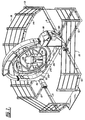
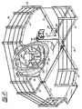
- the amusement device is basically comprised of a support stand 10 having a number of pivotably mounted front and rear support members 11 and side support members 12.
- a number of crowd control stanchions 13 are located at the distal ends of the support members 11 and 12.
- An additional set of extensions 14 are positioned between rearward support members 11 to form with crowd control cables 15, an inclosure defining a safety area.
- a control and hydraulic driving mechanism assembly 18 is provided at upright member 17. The assembly is used to rotate ring 19.
- ring 19 is pivotably mounted to upright members 16 and 17 by means of pivotable joints 20 and 21 respectively.
- Joints 20 and 21 allow ring 19 to rotate about an horizontal axis defined by the joints.
- Centrally located within ring 19 is a pair of support rings 22 forming a frame and bisecting each other at right angles.
- the frame is supported to ring 19 by means of pivotable joints 23 and 24.
- Frame 22 rotate on a second axis which lies at right angles to the horizontal axis defined by joints 20 and 21.
- a pair of bisecting crossbars 25 is centrally located within frame 22 and is adapted to receive a passenger seat 26.
- Securing means is provided to safely hold a passenger on seat 26.
- the securing means is comprised of a seatbelt 27, a body hold-down assembly 28 and a foot guard 29.
- side stabilizing bars 12 are hingedly mounted to frame 10 by means of a removable pin 30 which allows the disassembly of the crowd control extensions.
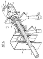
- the basic hydraulic driving system is comprised of a fluid reservoir 35, a hydraulic pump 36 and hydraulic drive assembly 37.
- the hydraulic drive assembly 37 is securely mounted to upright member 17 and is adapted to rotate ring 19 at a predetermined speed.
- the hydraulic assembly 38 shown in Figure 3b is a modified version of the hydraulic assembly 37 of Figure 3a as will be further described below.
- the assembly is basically comprised of a manifold 40 having fluid inlet 41 and outlet 42 and a pair of countered-balanced valves 43 and 44.
- a hydraulic motor 45 adapted to receive fluid from and to pass fluid to manifold 40.
- the assembly is supported on upright member 17 by means of a pair of torque plates 46 and 47 lying adjacent upright member 17 and contacting plate 17a attached to member 17.
- a driving shaft 48 is supported onto upright member 17 by means of a flange bearing 49.
- Shaft 48 extends therethrough and is supported onto torque plate 47 by means of a cam clutch 50.
- Shaft 48 is then mechanically connected to output shaft 51 of hydraulic motor 45 by means of a tapered lock flange 52.
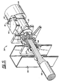
- an hydraulic drive and brake assembly shown generally in Figure 3b, is shown partially sectioned.
- the assembly is similarly comprised with a manifold 60, a pair of counter-balanced valves 61 and 62 and a hydraulic motor 63.
- a cam clutch 64 is attached to hydraulic motor 63.
- shaft 65 is supported onto an upright member 66 by means of a flange bearing 67.
- Shaft 65 is mechanically linked to output shaft 68 of motor 63 by means of a tapered lock flange 69.
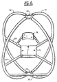
- FIG. 6 we have shown an isometric view of the support rings forming a frame or seat carriage assembly.
- the assembly is comprised of a first and second ring 70 and 71 bisecting each other at right angles.
- a tube centering plate 72 is provided at the bisecting point and is used to support the cage assembly within ring 19 as shown in Figures 1 and 2.
- the pair of crossbars 25 bisect each other at right angles and are fixedly mounted to rings 70 and 71 respectively.
- a bottom plate 75 is fixedly mounted at the bisecting point of crossbars 73 and 74 and is adapted to receive the passenger seat.
- a back plate 76 improves the overall structural integrity of the seat support arrangement.
- a third crossbar 77 extends laterally in the frontal section of the cage assembly between ring 70 and ring 71. Crossbar 77 is used to support the foot guard forming part of the passenger seat.
- FIG. 7 we have shown a side view of the passenger seat assembly using the amusement device of the present invention. It is basically comprised of a seat 26 having a foot support 81 and a back rest 82.
- a body hold down assembly 83 is pivotably mounted to foot rest 81 at pivot point 84.
- the body hold down assembly is comprised of a lap securing pad 85 onto which can be provided a pair of handles and a foot guard 86.
- a piston assembly 87 is provided between seat 26 and body hold down assembly 83 and permits the easy opening and closing of the body hold down assembly when a passenger is seated.
- the seat and body hold down assembly are entirely supported onto crossbars 73 and 74.
- FIG 8 we have shown an illustrative diagram of the improved amusement device of the present invention in the transport mode.
- a set of wheels 90 and 91 become disengaged from under base 10 to allow easy transportation of the amusement device.
- Each support member and its corresponding wheel is pivotably mounted about a pivot point 92 and 93.
Landscapes
- Engineering & Computer Science (AREA)
- Theoretical Computer Science (AREA)
- Aviation & Aerospace Engineering (AREA)
- Business, Economics & Management (AREA)
- Physics & Mathematics (AREA)
- Educational Administration (AREA)
- Educational Technology (AREA)
- General Physics & Mathematics (AREA)
- Handcart (AREA)
- Seats For Vehicles (AREA)
- Automotive Seat Belt Assembly (AREA)
Applications Claiming Priority (2)
| Application Number | Priority Date | Filing Date | Title |
|---|---|---|---|
| CA000546178A CA1285008C (en) | 1987-09-04 | 1987-09-04 | Spinning and rotating amusement device |
| CA546178 | 1987-09-04 |
Publications (3)
| Publication Number | Publication Date |
|---|---|
| EP0306295A2 true EP0306295A2 (de) | 1989-03-08 |
| EP0306295A3 EP0306295A3 (en) | 1989-09-13 |
| EP0306295B1 EP0306295B1 (de) | 1992-01-29 |
Family
ID=4136386
Family Applications (1)
| Application Number | Title | Priority Date | Filing Date |
|---|---|---|---|
| EP19880308065 Expired EP0306295B1 (de) | 1987-09-04 | 1988-08-31 | Vergnügungsvorrichtung |
Country Status (5)
| Country | Link |
|---|---|
| EP (1) | EP0306295B1 (de) |
| JP (1) | JPH01207092A (de) |
| AU (1) | AU601303B2 (de) |
| CA (1) | CA1285008C (de) |
| DE (1) | DE3868189D1 (de) |
Cited By (5)
| Publication number | Priority date | Publication date | Assignee | Title |
|---|---|---|---|---|
| WO1994024651A1 (en) * | 1993-04-16 | 1994-10-27 | Hesperus Limited | Computer environment |
| BG825Y1 (bg) * | 2005-01-13 | 2006-08-31 | ДИМИТРОВ Иван | Полифункционална люлка |
| CN104192324A (zh) * | 2014-09-03 | 2014-12-10 | 上海恒润数字科技股份有限公司 | 摆臂式自转同步空间三维模拟器 |
| CN110152312A (zh) * | 2019-07-08 | 2019-08-23 | 青岛海科虚拟现实研究院 | 一种基于vr模拟的飞行体感装置 |
| CN113955154A (zh) * | 2021-12-20 | 2022-01-21 | 中国人民解放军63919部队 | 一种航空/航天座椅 |
Families Citing this family (1)
| Publication number | Priority date | Publication date | Assignee | Title |
|---|---|---|---|---|
| US10258893B2 (en) * | 2017-04-25 | 2019-04-16 | Universal City Studios Llc | Annular motion simulation amusement park attraction |
Family Cites Families (7)
| Publication number | Priority date | Publication date | Assignee | Title |
|---|---|---|---|---|
| FR369125A (fr) * | 1906-08-11 | 1906-12-29 | Nathaniel Gateo Warth | Appareil d'amusement |
| GB131363A (de) * | 1918-05-17 | 1919-08-28 | ||
| US2780460A (en) * | 1953-01-28 | 1957-02-05 | Lee U Eyerly | Rotary amusement device |
| US3085354A (en) * | 1957-01-31 | 1963-04-16 | Westinghouse Electric Corp | Multi-gimbal flight simulator |
| US3083037A (en) * | 1960-05-27 | 1963-03-26 | Donald W Gordon | Exercising and recreational apparatus |
| US3141669A (en) * | 1963-04-26 | 1964-07-21 | Chul Yun | Hoop device |
| US4402500A (en) * | 1981-03-27 | 1983-09-06 | Coles William E | Amusement device for simulating weightlessness |
-
1987
- 1987-09-04 CA CA000546178A patent/CA1285008C/en not_active Expired - Lifetime
-
1988
- 1988-08-31 EP EP19880308065 patent/EP0306295B1/de not_active Expired
- 1988-08-31 DE DE8888308065T patent/DE3868189D1/de not_active Expired - Fee Related
- 1988-09-02 JP JP22029688A patent/JPH01207092A/ja active Pending
- 1988-09-02 AU AU21767/88A patent/AU601303B2/en not_active Ceased
Cited By (7)
| Publication number | Priority date | Publication date | Assignee | Title |
|---|---|---|---|---|
| WO1994024651A1 (en) * | 1993-04-16 | 1994-10-27 | Hesperus Limited | Computer environment |
| BG825Y1 (bg) * | 2005-01-13 | 2006-08-31 | ДИМИТРОВ Иван | Полифункционална люлка |
| CN104192324A (zh) * | 2014-09-03 | 2014-12-10 | 上海恒润数字科技股份有限公司 | 摆臂式自转同步空间三维模拟器 |
| CN104192324B (zh) * | 2014-09-03 | 2016-02-10 | 上海恒润数字科技股份有限公司 | 摆臂式自转同步空间三维模拟器 |
| CN110152312A (zh) * | 2019-07-08 | 2019-08-23 | 青岛海科虚拟现实研究院 | 一种基于vr模拟的飞行体感装置 |
| CN113955154A (zh) * | 2021-12-20 | 2022-01-21 | 中国人民解放军63919部队 | 一种航空/航天座椅 |
| CN113955154B (zh) * | 2021-12-20 | 2022-04-15 | 中国人民解放军63919部队 | 一种航空/航天座椅 |
Also Published As
| Publication number | Publication date |
|---|---|
| EP0306295A3 (en) | 1989-09-13 |
| AU2176788A (en) | 1989-03-09 |
| EP0306295B1 (de) | 1992-01-29 |
| DE3868189D1 (de) | 1992-03-12 |
| JPH01207092A (ja) | 1989-08-21 |
| AU601303B2 (en) | 1990-09-06 |
| CA1285008C (en) | 1991-06-18 |
Similar Documents
| Publication | Publication Date | Title |
|---|---|---|
| US4824099A (en) | Rotating amusement device | |
| CA1227435A (en) | Drive motor, which is supplied by an energy source, for disk-shaped or wheel-shaped members with a control mechanism | |
| EP0306295A2 (de) | Vergnügungsvorrichtung | |
| US3947033A (en) | Steer roping training device | |
| SE458502B (sv) | Saett och rullstol foer att hantera en person med begraensad roerelsefoermaaga | |
| WO1988008362A1 (en) | Manually operated portable mixing device | |
| US4007926A (en) | Mobile amusement ride | |
| CA2088566A1 (en) | Pedal boat | |
| JPH03212285A (ja) | 宙返りブランコおよびその駆動方法 | |
| EP1577199A1 (de) | Tragbarer Motorroller mit Mittelradantrieb | |
| US4620700A (en) | Occupant propelled roundabout | |
| US5697701A (en) | Fluid mixer providing gentle agitation | |
| US1799409A (en) | Amusement apparatus | |
| GB2133996A (en) | Speed restrictor for children's roundabouts | |
| CN205912687U (zh) | 一种抓鸡圆盘 | |
| US2780460A (en) | Rotary amusement device | |
| CN215028181U (zh) | 一种斜面旋转式生物液体混匀仪 | |
| CN213432945U (zh) | 一种娱乐场儿童玩的摇摇机设备 | |
| US4018435A (en) | Playground apparatus | |
| CN211062138U (zh) | 一种礼品机自动补给装置 | |
| US2516049A (en) | Occupant propelled roundabout | |
| CN113413616A (zh) | 一种摇摆式曲面游乐设备 | |
| CN223263378U (zh) | 一种旋转支撑装置 | |
| US2797099A (en) | Amusement ride | |
| US2925272A (en) | Merry-go-round |
Legal Events
| Date | Code | Title | Description |
|---|---|---|---|
| PUAI | Public reference made under article 153(3) epc to a published international application that has entered the european phase |
Free format text: ORIGINAL CODE: 0009012 |
|
| AK | Designated contracting states |
Kind code of ref document: A2 Designated state(s): DE ES FR GB GR IT NL SE |
|
| PUAL | Search report despatched |
Free format text: ORIGINAL CODE: 0009013 |
|
| AK | Designated contracting states |
Kind code of ref document: A3 Designated state(s): DE ES FR GB GR IT NL SE |
|
| 17P | Request for examination filed |
Effective date: 19900228 |
|
| 17Q | First examination report despatched |
Effective date: 19901127 |
|
| GRAA | (expected) grant |
Free format text: ORIGINAL CODE: 0009210 |
|
| AK | Designated contracting states |
Kind code of ref document: B1 Designated state(s): DE ES FR GB GR IT NL SE |
|
| PG25 | Lapsed in a contracting state [announced via postgrant information from national office to epo] |
Ref country code: GR Free format text: LAPSE BECAUSE OF FAILURE TO SUBMIT A TRANSLATION OF THE DESCRIPTION OR TO PAY THE FEE WITHIN THE PRESCRIBED TIME-LIMIT Effective date: 19920129 Ref country code: FR Effective date: 19920129 Ref country code: ES Free format text: THE PATENT HAS BEEN ANNULLED BY A DECISION OF A NATIONAL AUTHORITY Effective date: 19920129 Ref country code: SE Effective date: 19920129 Ref country code: NL Effective date: 19920129 Ref country code: IT Free format text: LAPSE BECAUSE OF FAILURE TO SUBMIT A TRANSLATION OF THE DESCRIPTION OR TO PAY THE FEE WITHIN THE PRE;WARNING: LAPSES OF ITALIAN PATENTS WITH EFFECTIVE DATE BEFORE 2007 MAY HAVE OCCURRED AT ANY TIME BEFORE 2007. THE CORRECT EFFECTIVE DATE MAY BE DIFFERENT FROM THE ONE RECORDED.SCRIBED TIME-LIMIT Effective date: 19920129 |
|
| REF | Corresponds to: |
Ref document number: 3868189 Country of ref document: DE Date of ref document: 19920312 |
|
| EN | Fr: translation not filed | ||
| NLV1 | Nl: lapsed or annulled due to failure to fulfill the requirements of art. 29p and 29m of the patents act | ||
| PG25 | Lapsed in a contracting state [announced via postgrant information from national office to epo] |
Ref country code: GB Effective date: 19920831 |
|
| PLBE | No opposition filed within time limit |
Free format text: ORIGINAL CODE: 0009261 |
|
| STAA | Information on the status of an ep patent application or granted ep patent |
Free format text: STATUS: NO OPPOSITION FILED WITHIN TIME LIMIT |
|
| 26N | No opposition filed | ||
| GBPC | Gb: european patent ceased through non-payment of renewal fee |
Effective date: 19920831 |
|
| PG25 | Lapsed in a contracting state [announced via postgrant information from national office to epo] |
Ref country code: DE Effective date: 19930602 |