EP0306142A2 - Lampenreflektor und eine den Lampenreflektor aufweisende Vorrichtung - Google Patents
Lampenreflektor und eine den Lampenreflektor aufweisende Vorrichtung Download PDFInfo
- Publication number
- EP0306142A2 EP0306142A2 EP88306857A EP88306857A EP0306142A2 EP 0306142 A2 EP0306142 A2 EP 0306142A2 EP 88306857 A EP88306857 A EP 88306857A EP 88306857 A EP88306857 A EP 88306857A EP 0306142 A2 EP0306142 A2 EP 0306142A2
- Authority
- EP
- European Patent Office
- Prior art keywords
- lamp
- reflector
- reflective surface
- ellipsoid
- major axis
- Prior art date
- Legal status (The legal status is an assumption and is not a legal conclusion. Google has not performed a legal analysis and makes no representation as to the accuracy of the status listed.)
- Granted
Links
- 239000011521 glass Substances 0.000 claims description 6
- 238000005286 illumination Methods 0.000 claims description 3
- 239000011248 coating agent Substances 0.000 claims 1
- 238000000576 coating method Methods 0.000 claims 1
- 239000000463 material Substances 0.000 claims 1
- 238000009826 distribution Methods 0.000 description 14
- 230000000694 effects Effects 0.000 description 4
- 238000009827 uniform distribution Methods 0.000 description 3
- 239000004411 aluminium Substances 0.000 description 2
- 229910052782 aluminium Inorganic materials 0.000 description 2
- XAGFODPZIPBFFR-UHFFFAOYSA-N aluminium Chemical compound [Al] XAGFODPZIPBFFR-UHFFFAOYSA-N 0.000 description 2
- 238000003892 spreading Methods 0.000 description 2
- 238000004519 manufacturing process Methods 0.000 description 1
- 229910052751 metal Inorganic materials 0.000 description 1
- 239000002184 metal Substances 0.000 description 1
- 229910001507 metal halide Inorganic materials 0.000 description 1
- 150000005309 metal halides Chemical class 0.000 description 1
- 238000003825 pressing Methods 0.000 description 1
- 230000005855 radiation Effects 0.000 description 1
- 230000003014 reinforcing effect Effects 0.000 description 1
Images

Classifications
-
- F—MECHANICAL ENGINEERING; LIGHTING; HEATING; WEAPONS; BLASTING
- F21—LIGHTING
- F21V—FUNCTIONAL FEATURES OR DETAILS OF LIGHTING DEVICES OR SYSTEMS THEREOF; STRUCTURAL COMBINATIONS OF LIGHTING DEVICES WITH OTHER ARTICLES, NOT OTHERWISE PROVIDED FOR
- F21V7/00—Reflectors for light sources
- F21V7/04—Optical design
- F21V7/09—Optical design with a combination of different curvatures
Definitions
- This invention relates to a lamp reflector suitable for use in association with a transversely mounted, discharge arc lamp.
- the invention also relates to a lamp arrangement including said lamp reflector in combination with a transversely mounted discharge arc lamp and it relates particularly, though not exclusively, to a sealed beam lamp arrangement including a transversely mounted, pinch-sealed discharge arc lamp.
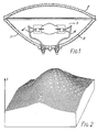
- Figure 1 of the accompanying drawings shows a transverse, cross-sectional view through a known sealed beam lamp arrangement which comprises a reflector envelope 1 having a parabolic reflective surface 2, a double-ended pinch sealed discharge arc lamp 3 mounted transversely in the reflector envelope on a pair of electrical lead-in members 4, 4′ and a cover 5, which normally incorporates a prismatic spreader lens, sealed to the reflector envelope.
- a sealed beam lamp arrangement having application in photoprinting and allied fields, includes a high pressure metal halide discharge arc lamp emissive of radiation in the wavelength range from 315nm to 450nm.
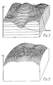
- Figure 2 of the drawings shows a distribution of light intensity 'I', over a substantially square field, derived from a sealed beam lamp arrangement of the kind illustrated in Figure 1. This distribution has a pronounced central peak and, for many applications, a more uniform distribution of light intensity would be desirable.
- a lamp reflector suitable for use in association with a transversely mounted discharge arc lamp, the reflector being dish-shaped and comprising a reflective surface of which a part conforms substantially to an ellipsoid and of which a further part does not so conform, said further part being so shaped and positioned as to distribute light to a region in the field of illumination which, if said reflective surface conformed fully to said ellipsoid, would be masked by an end portion of, and or an end-mounting for, a said discharge arc lamp mounted transversely with respect to a major axis of the ellipsoid.
- said part which conforms substantially to an ellipsoid encompasses an ellipsoidal surface which is facetted.
- the lamp reflector is particularly suitable for use in association with a transversely mounted pinch sealed discharge arc lamp.
- a lamp reflector of the kind defined gives rise to a distribution of light intensity which, as compared with hitherto known configurations, is remarkably uniform.
- the lamp reflector may be used in association with either a single or a double ended, pinch sealed discharge arc lamp and, in the latter case, said reflective surface may comprise two said further parts arranged symmetrically on either side of a plane containing said major axis of the ellipsoid.
- Said further part or parts may conform substantially to a sphere, the centre of curvature of the sphere being offset from said major axis of the ellipsoid.
- said further part or parts may conform substantially to a parabaloid with the focus of the parabaloid being offset from said major axis.
- Facets may be provided on the ellipsoidal part of said reflective surface in order to further improve the uniformity of the distribution of light intensity and said facets may comprise contiguous, annular bands encircling said major axis of the ellipsoid. Each said facet may be flat in the transverse direction thereof.
- the facets are configured so as to achieve greater spreading of light closer to the centre of the reflector and, to this end, the widths of successive ones of at least some of said contiguous annular bands increase progressively in a direction approaching the centre of the reflector.
- the reflective surface may be stippled.
- a lamp arrangement including a lamp reflector in accordance with said first aspect of the invention in combination with a transverely mounted discharge arc lamp.
- the lamp arrangement may be a sealed beam lamp unit wherein said reflector comprises a glass envelope formed with said reflective surface and including a cover sealed to said glass envelope.
- said cover and or the reflective surface may be stippled and the cover may incorporate a spreader lens.
- Figure 3 of the drawings shows a distribution of light intensity 'I' derived using a reflector which is similar to that shown in Figure 1 but uses an ellipsoidal reflective surface to distribute the light.
- the distribution of light intensity 'I' has a central peak but, in addition, exhibits two troughs, one on either side of the peak, attributable to "shadows" cast by the pinches of, and or end-mountings for, a transversely mounted discharge arc lamp.
- the shape of the ellipsoidal reflective surface can be modified in such a way as to distribute light to a region which would otherwise be masked by a pinch of the discharge arc lamp, and or its support, and this has the effect of reducing the prominence of the central peak while reinforcing the intensity in the troughs.
- the inventor finds that the resulting distribution of light intensity has a markedly improved uniformity as compared with that derived using an entirely ellipsoidal reflector or using a paraboloidal reflective surface in combination with a prismatic spreader lens.
- a lamp arrangement 10 comprises a dish-shaped reflector envelope 11, in the form of a glass pressing, in combination with a double-ended pinch-sealed discharge arc lamp 12 mounted transversely within the reflector envelope.
- electrical lead-in members 13, 13′ used to support the lamp are represented in broken outline only.
- Envelope 11 has a reflective inner surface 14 which, in this embodiment, is formed by a thin layer of aluminium though, alternatively a dichroic layer, for example, could be used.
- One specific region of the reflective surface conforms substantially to an ellipsoid having a major axis XX, whereas two other surface regions 16, 16′ close to the centre of the reflector envelope, and arranged symmetrically on either side of a plane YY containing axis XX, are substantially spherical.
- Each spherical surface region 16, 16′ has a radius of curvature R, R′ centred at a point C, C′ which is offset from axis XX on a respective side of plane YY.
- the discharge arc lamp 12 is mounted symmetrically with respect to plane YY, at or near the focus F of the ellipsoidal surface 15, with the longitudinal axis ZZ of the lamp intersecting axis XX orthogonally.
- the spherical regions 16, 16′ are effective to distribute light to regions which, if the reflective surface had been entirely ellipsoidal, would be masked by the lamp pinches P, P′ and or the lamp end-mountings, thereby providing a more uniform distribution of light intensity.
- Uniformity may be further improved by providing facets on the ellipsoidal surface 15 and, in this embodiment, the facets comprise a plurality of contiguous, annular bands 17 enclosing the major axis XX.
- Each facet which is flat in the transverse direction thereof, has the shape of a truncated cone.
- the facets are configured to produce a greater spreading of light closer to the centre of the reflector and, to this end, the width of successive bands increases progressively in a direction approaching the centre of the reflector envelope, except for the innermost band 17′ which is made relatively narrow for ease of manufacture.
- Figure 5 illustrates the distribution of light intensity 'I' attainable using a reflector of the kind illustrated in Figures 4. This distribution shows a remarkable degree of uniformity and exhibits no substantial fall off of the kind shown in the distributions of Figures 2 and 3.
- the embodiment of Figures 4 relates to a sealed beam lamp arrangement, there being a glass cover 18 sealed to the envelope 11.
- the front face of cover 18 and or the reflective surface 14 may have a stippled pattern effective to further improve the uniformity of the distribution and, if desired, the cover may also incorporate a spreader lens.
- the cover may be omitted, and the reflector envelope could be formed from pressed sheet metal eg aluminium.
- the embodiment shown in Figures 4 has spherically shaped surface regions 16, 16′, the inventor envisages that alternatively shaped surface could be used to achieve the desired effect and, in particular, paraboloidal surfaces are envisaged.
- a reflector in accordance with this invention could also be used in association with a single-ended, pinch sealed discharge arc lamp and, in that circumstance, only one said region 16 would be needed.
- the invention is also applicable to transversely mounted discharge arc lamps, other than pinch sealed lamps, wherein an end portion or portions and or a lamp end-mounting obscure light reflected at the reflector.
- a lamp arrangement including a reflector in accordance with this invention finds particular application in photoprinting and allied fields but could be used in other applications requiring a uniform distribution of light intensity, for example in connection with plant cultivation and interior lighting (e.g. wall flooding and uplighting).
Landscapes
- Engineering & Computer Science (AREA)
- General Engineering & Computer Science (AREA)
- Vessels And Coating Films For Discharge Lamps (AREA)
- Non-Portable Lighting Devices Or Systems Thereof (AREA)
Applications Claiming Priority (2)
| Application Number | Priority Date | Filing Date | Title |
|---|---|---|---|
| GB8720471 | 1987-08-29 | ||
| GB878720471A GB8720471D0 (en) | 1987-08-29 | 1987-08-29 | Lamp reflector |
Publications (3)
| Publication Number | Publication Date |
|---|---|
| EP0306142A2 true EP0306142A2 (de) | 1989-03-08 |
| EP0306142A3 EP0306142A3 (en) | 1990-03-14 |
| EP0306142B1 EP0306142B1 (de) | 1993-04-28 |
Family
ID=10623055
Family Applications (1)
| Application Number | Title | Priority Date | Filing Date |
|---|---|---|---|
| EP19880306857 Expired - Lifetime EP0306142B1 (de) | 1987-08-29 | 1988-07-26 | Lampenreflektor und eine den Lampenreflektor aufweisende Vorrichtung |
Country Status (3)
| Country | Link |
|---|---|
| EP (1) | EP0306142B1 (de) |
| DE (1) | DE3880590T2 (de) |
| GB (1) | GB8720471D0 (de) |
Cited By (1)
| Publication number | Priority date | Publication date | Assignee | Title |
|---|---|---|---|---|
| AT406079B (de) * | 1989-10-17 | 2000-02-25 | Zizala Lichtsysteme Gmbh | Fahrzeugscheinwerfer |
Family Cites Families (4)
| Publication number | Priority date | Publication date | Assignee | Title |
|---|---|---|---|---|
| JPS58155701U (ja) * | 1982-04-14 | 1983-10-18 | 小糸工業株式会社 | 無影灯用反射鏡 |
| US4473872A (en) * | 1982-05-21 | 1984-09-25 | Gte Products Corporation | Par spot lamp |
| US4453203A (en) * | 1982-07-19 | 1984-06-05 | Harvey Hubbell Incorporated | Lighting fixture reflector |
| DD207826A3 (de) * | 1982-08-02 | 1984-03-14 | Christfried Symanowski | Reflektorsystem fuer beleuchtungsoptiken |
-
1987
- 1987-08-29 GB GB878720471A patent/GB8720471D0/en active Pending
-
1988
- 1988-07-26 EP EP19880306857 patent/EP0306142B1/de not_active Expired - Lifetime
- 1988-07-26 DE DE19883880590 patent/DE3880590T2/de not_active Expired - Fee Related
Cited By (1)
| Publication number | Priority date | Publication date | Assignee | Title |
|---|---|---|---|---|
| AT406079B (de) * | 1989-10-17 | 2000-02-25 | Zizala Lichtsysteme Gmbh | Fahrzeugscheinwerfer |
Also Published As
| Publication number | Publication date |
|---|---|
| DE3880590D1 (de) | 1993-06-03 |
| DE3880590T2 (de) | 1993-11-18 |
| EP0306142B1 (de) | 1993-04-28 |
| GB8720471D0 (en) | 1987-10-07 |
| EP0306142A3 (en) | 1990-03-14 |
Similar Documents
| Publication | Publication Date | Title |
|---|---|---|
| CA1203219A (en) | Lighting fixture reflector | |
| US4242725A (en) | Light reflector structure | |
| US4855886A (en) | Luminaire having a faceted reflecting surface | |
| CA1193645A (en) | Reflector lamp | |
| US4293901A (en) | Reflector system having sharp light cutoff characteristics | |
| US5016152A (en) | Focused light source and method | |
| JPS6346921B2 (de) | ||
| US5568967A (en) | Electric lamp with reflector | |
| CN100473896C (zh) | 照明器及其薄板格栅 | |
| US5645344A (en) | Luminaire | |
| CA2188044C (en) | Reflector incandescent lamp | |
| CA2624733C (en) | Faceted par lamp | |
| EP1606552B1 (de) | Leuchte | |
| US4536834A (en) | R lamp having an improved neck section for increasing the useful light output | |
| JPH05258736A (ja) | 改良されたレンズを有するリフレクタランプ | |
| EP0306142B1 (de) | Lampenreflektor und eine den Lampenreflektor aufweisende Vorrichtung | |
| US5726525A (en) | Electric reflector lamp | |
| US4656386A (en) | R lamp having an improved dome portion for increasing the useful light output | |
| EP1472491B1 (de) | Leuchte mit leuchtenraster, für rohrförmige lampe | |
| HU191446B (en) | Reflector lamp | |
| EP0062354A2 (de) | "Sealed beam" reflektierende Lampe | |
| JPH0432497B2 (de) | ||
| US4896072A (en) | Flashbulb with a heat shield | |
| JPS6310102A (ja) | 透過形画像表示装置の照明装置 | |
| GB2109990A (en) | Incandescent lamp |
Legal Events
| Date | Code | Title | Description |
|---|---|---|---|
| PUAI | Public reference made under article 153(3) epc to a published international application that has entered the european phase |
Free format text: ORIGINAL CODE: 0009012 |
|
| AK | Designated contracting states |
Kind code of ref document: A2 Designated state(s): DE GB NL |
|
| PUAL | Search report despatched |
Free format text: ORIGINAL CODE: 0009013 |
|
| AK | Designated contracting states |
Kind code of ref document: A3 Designated state(s): DE GB NL |
|
| 17P | Request for examination filed |
Effective date: 19900504 |
|
| 17Q | First examination report despatched |
Effective date: 19920930 |
|
| GRAA | (expected) grant |
Free format text: ORIGINAL CODE: 0009210 |
|
| AK | Designated contracting states |
Kind code of ref document: B1 Designated state(s): DE GB NL |
|
| RAP2 | Party data changed (patent owner data changed or rights of a patent transferred) |
Owner name: GE LIGHTING LIMITED |
|
| REF | Corresponds to: |
Ref document number: 3880590 Country of ref document: DE Date of ref document: 19930603 |
|
| NLT2 | Nl: modifications (of names), taken from the european patent patent bulletin |
Owner name: GE LIGHTING LIMITED TE ENFIELD, GROOT-BRITTANNIE. |
|
| PLBE | No opposition filed within time limit |
Free format text: ORIGINAL CODE: 0009261 |
|
| STAA | Information on the status of an ep patent application or granted ep patent |
Free format text: STATUS: NO OPPOSITION FILED WITHIN TIME LIMIT |
|
| 26N | No opposition filed | ||
| PGFP | Annual fee paid to national office [announced via postgrant information from national office to epo] |
Ref country code: NL Payment date: 19950627 Year of fee payment: 8 |
|
| PG25 | Lapsed in a contracting state [announced via postgrant information from national office to epo] |
Ref country code: NL Effective date: 19970201 |
|
| NLV4 | Nl: lapsed or anulled due to non-payment of the annual fee |
Effective date: 19970201 |
|
| REG | Reference to a national code |
Ref country code: GB Ref legal event code: IF02 |
|
| PGFP | Annual fee paid to national office [announced via postgrant information from national office to epo] |
Ref country code: DE Payment date: 20020730 Year of fee payment: 15 |
|
| PGFP | Annual fee paid to national office [announced via postgrant information from national office to epo] |
Ref country code: GB Payment date: 20030723 Year of fee payment: 16 |
|
| PG25 | Lapsed in a contracting state [announced via postgrant information from national office to epo] |
Ref country code: DE Free format text: LAPSE BECAUSE OF NON-PAYMENT OF DUE FEES Effective date: 20040203 |
|
| PG25 | Lapsed in a contracting state [announced via postgrant information from national office to epo] |
Ref country code: GB Free format text: LAPSE BECAUSE OF NON-PAYMENT OF DUE FEES Effective date: 20040726 |
|
| GBPC | Gb: european patent ceased through non-payment of renewal fee |
Effective date: 20040726 |