EP0304774A2 - Method for generating a signal corresponding to the flow rate of a flowing conductive medium - Google Patents
Method for generating a signal corresponding to the flow rate of a flowing conductive medium Download PDFInfo
- Publication number
- EP0304774A2 EP0304774A2 EP88113286A EP88113286A EP0304774A2 EP 0304774 A2 EP0304774 A2 EP 0304774A2 EP 88113286 A EP88113286 A EP 88113286A EP 88113286 A EP88113286 A EP 88113286A EP 0304774 A2 EP0304774 A2 EP 0304774A2
- Authority
- EP
- European Patent Office
- Prior art keywords
- field
- signal
- constant
- medium
- alternating
- Prior art date
- Legal status (The legal status is an assumption and is not a legal conclusion. Google has not performed a legal analysis and makes no representation as to the accuracy of the status listed.)
- Granted
Links
Images
Classifications
-
- G—PHYSICS
- G01—MEASURING; TESTING
- G01F—MEASURING VOLUME, VOLUME FLOW, MASS FLOW OR LIQUID LEVEL; METERING BY VOLUME
- G01F1/00—Measuring the volume flow or mass flow of fluid or fluent solid material wherein the fluid passes through a meter in a continuous flow
- G01F1/56—Measuring the volume flow or mass flow of fluid or fluent solid material wherein the fluid passes through a meter in a continuous flow by using electric or magnetic effects
- G01F1/58—Measuring the volume flow or mass flow of fluid or fluent solid material wherein the fluid passes through a meter in a continuous flow by using electric or magnetic effects by electromagnetic flowmeters
- G01F1/60—Circuits therefor
Definitions
- the invention relates to methods for generating a signal which corresponds to the current strength of a flowing, electrically conductive medium, and circuit arrangements for carrying out the method.
- the object of the invention is to provide a method according to the preamble of claim 1 or claim 2, which combines the advantages of both known methods as possible and excludes the disadvantages of both known methods as possible.
- the process is preferably controlled in the following way: With a signal zero or almost corresponding to a current strength of the flowing medium zero or the DC field is used to generate the signal, almost zero.
- the alternating field is used to generate the signal.
- the DC field is used to generate the signal.
- the alternating field is used to generate the signal.
- the alternating field is used to generate the signal regardless of strong or weak fluctuations in the signal over time.
- the constant field can be monopolar or bipolar.
- the advantage is obtained that the circuit can be carried out with the simplest switching means.
- the advantage of a bipolar DC field is that the installed power for generating the same signal amplitude as for a monopolar field can be considerably lower (smaller power supply).
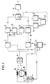
- a tube 4 is shown schematically, through which an electrically conductive medium flows. Electrodes 5 protrude into the tube 4 from opposite sides, each of which leads to an input of an input amplifier 6.
- the electrodes 5 detect potentials in the flowing medium which are different from one another when the medium is penetrated by a magnetic field generated by coils 3a, 3b.
- a DC generator 1 is provided to generate the DC magnetic field and a generator 2 is provided to generate an alternating magnetic field. Both generators 1, 2 are parallel to one another with the coils 3a and 3b in a circuit.
- the generators are controlled by a clock generator 15 in the clock A1 and B1 shown in FIGS. 2 and 3 for the two methods.
- the voltage U f reaches the inputs of two synchronous rectifiers 7 and 8.
- the synchronous rectifier 7 serves to rectify the voltage component u w corresponding to the alternating field.
- Synchronous rectifier 8 serves to rectify the component U g corresponding to the DC field. This too Rectifiers 7, 8 are controlled by the clock generator 15, specifically in the clock cycle A2 or B2 shown in FIG. 2 or 3.
- the synchronous rectifier 7 outputs the voltage components rectified by it to an evaluation circuit 9 for the alternating field.
- the synchronous rectifier 8 passes the voltage components rectified by it to an evaluation circuit 10 for the DC field.
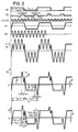
- the generators 1 and 2 generate a bipolar DC field 0 ⁇ 1 and an alternating field 0 ⁇ 2. These fields are superimposed on a field 0 ⁇ .
- the voltage U f has essentially the same profile as the field 0 ⁇ .
- the portion of the voltage corresponding to the DC field is evaluated in sections t g1 and t g2 . These sections are located at the ends of the half-periods T g / 2 of the constant field.
- the voltages are subtracted from one another in two successive sections t g1 and t g2 with the correct sign.
- You get (U p + u g ) tg1 - (U p - u g ) tg2 2u g
- the portions originating from the alternating field are added with the correct sign.
- the switch 13 is actuated as a function of the course of the voltage component 2u g in the manner described at the beginning.
- a detector 16 is provided which is responsive to changes of 2u g per unit of time, and, if these changes exceed a preset Audio measure per unit time, is operated via an OR gate 17 the switch. 13
- a detector 15 is provided for this purpose, which actuates the changeover switch 13 via the OR gate 17 when the voltage components 2u g exceed a predetermined level, for example due to interference.
- the changeover switch 13 is actuated in the same way as in the method according to claim 1.
Abstract
Description
Die Erfindung betrifft Verfahren zur Erzeugung eines Signals, das der Stromstärke eines fließenden, elektrisch leitenden Mediums entspricht, und Schaltungsanordnungen zur Durchführung der Verfahren.The invention relates to methods for generating a signal which corresponds to the current strength of a flowing, electrically conductive medium, and circuit arrangements for carrying out the method.
Es ist bei solchen Verfahren bekannt, als Magnetfeld allein ein sich mit verhältnismäßig langer Periode periodisch änderndes Gleichfeld anzuwenden.In such methods, it is known to use as the magnetic field alone a constant field periodically changing with a relatively long period.
- a) Ist die Stromstärke des fließenden Mediums Null, so ist auch das Signal stabil Null.a) If the current strength of the flowing medium is zero, the signal is also stable zero.
- b) Bei gleichmäßigem homogenem Strom des fließenden Mediums entspricht das Signal mit hoher Genauigkeit der Stromstärke des fließenden Mediums.b) With a uniform, homogeneous flow of the flowing medium, the signal corresponds with high accuracy to the current strength of the flowing medium.
- c) Das Systemverhalten ist weitgehend temperaturunempfindlich.c) The system behavior is largely insensitive to temperature.
- d) Das Magnetfeld ist mit verhältnismäßig geringer Leistung zu erzeugen.d) The magnetic field is to be generated with relatively low power.
- a) Bei stark schwankendem Strom folgt das Signal Änderungen der Stromstärke des fließenden Mediums nur träge.a) In the event of a strongly fluctuating current, the signal follows changes in the current strength of the flowing medium only slowly.
- b) Das Signal ist sehr empfindlich gegenüber elektrisch Leitfähigskeits-Inhomogenität im Strom des fließenden Mediums. Dem Signal kann dadurch ein Störanteil überlagert werden, der das Zehnfache des Signals übersteigt, so daß das Signal als Ist-Signal in schnellen Regelprozessen nicht verwendbar ist.b) The signal is very sensitive to electrical conductivity inhomogeneity in the flow of the flowing medium. As a result, the signal can be superimposed with a disturbance component that exceeds ten times the signal, so that the signal cannot be used as an actual signal in fast control processes.
Es ist bei solchen Verfahren andererseits auch bekannt, als Magnetfeld allein ein Wechselfeld verhältnismäßig kurzer Periode anzuwenden.In such methods, on the other hand, it is also known to use an alternating field of a relatively short period as the magnetic field alone.
- a) Das Signal folgt sehr rasch Änderungen der Stromstärke des fließenden Mediums und ist daher gut als Ist-Signal in schnellen Regelprozessen verwendbar.a) The signal follows changes in the current strength of the flowing medium very quickly and can therefore be used as an actual signal in fast control processes.
- b) Das Signal ist unempfindlich gegenüber elektrischen Leitfähigkeitsinhomogenitäten im Strom des fließenden Mediums.b) The signal is insensitive to electrical conductivity inhomogeneities in the flow of the flowing medium.
- a) Das Signal ist empfindlich gegenüber niederfrequenten äußeren Störungen.a) The signal is sensitive to low-frequency external interference.
- b) Das System ist, bedingt durch die Wirbelstromanteile im Magnetkreis, temperaturempfindlich.b) Due to the eddy current components in the magnetic circuit, the system is temperature sensitive.
Aufgabe der Erfindung ist es, ein Verfahren nach dem Oberbegriff des Anspruchs 1 bzw. des Anspruchs 2 anzugeben, das die Vorteile beider bekannter Verfahren möglichst vereinigt und die Nachteile beider bekannter Verfahren möglichst ausschließt.The object of the invention is to provide a method according to the preamble of
Zwei grundsätzlich voneinander unabhängige Lösungen dieser Aufgabe sind in den Ansprüchen 1 und 2 angegeben. Die Lösungen können aber auch nach Anspruch 3 vereinigt werden.Two fundamentally independent solutions to this problem are given in
Das Verfahren wird bevorzugt in folgender Weise gesteuert:
Bei einem einer Stromstärke Null oder nahezu Null des fließenden Mediums entsprechenden Signal Null oder nahezu Null wird das Gleichfeld zur Erzeugung des Signals verwendet.The process is preferably controlled in the following way:
With a signal zero or almost corresponding to a current strength of the flowing medium zero or the DC field is used to generate the signal, almost zero.
Bei einem einer zeitlich stark schwankenden Stromstärke des fließenden Mediums entsprechenden zeitlich stark schwankenden Signal wird das Wechselfeld zur Erzeugung des Signals verwendet.In the case of a signal that fluctuates in time and fluctuates in time with a strongly fluctuating current of the flowing medium, the alternating field is used to generate the signal.
Bei einem einer konstanten oder zeitlich schwach schwankenden Stromstärke des fließenden Mediums entsprechenden zeitlich schwach schwankenden Signal ohne überlagerte Störspitzen wird das Gleichfeld zur Erzeugung des Signals verwendet.In the case of a signal which fluctuates slightly in time or which fluctuates slightly over time in the flowing medium and does not have superimposed interference peaks, the DC field is used to generate the signal.
Bei einem einer konstanten oder zeitlich schwach schwankenden Stromstärke des fließenden Mediums entsprechenden zeitlich schwach schwankenden Signal mit überlagerten Störspitzen wird das Wechselfeld zur Erzeugung des Signals verwendet.In the case of a signal with a superimposed interference peaks corresponding to a constant or weakly fluctuating current strength of the flowing medium, the alternating field is used to generate the signal.
Bei sehr starken Störungen des Signals wird unabhängig von zeitlich starken oder schwachen Schwankungen des Signals das Wechselfeld zur Erzeugung des Signals verwendet.In the event of very strong interference in the signal, the alternating field is used to generate the signal regardless of strong or weak fluctuations in the signal over time.
Das Gleichfeld kann gemäß Anspruch 4 bzw. 5 monopolar oder bipolar sein.The constant field can be monopolar or bipolar.
Bei monopolarem Gleichfeld erhält man den Vorteil, daß die Schaltung mit einfachsten Schaltmitteln ausgeführt werden kann.
Bei bipolarem Gleichfeld erhält man den Vorteil, daß die installierte Leistung zur Erzeugung der gleichen Signalamplitude wie bei monopolarem Feld erheblich geringer sein kann (kleineres Netzteil).With a monopolar DC field, the advantage is obtained that the circuit can be carried out with the simplest switching means.
The advantage of a bipolar DC field is that the installed power for generating the same signal amplitude as for a monopolar field can be considerably lower (smaller power supply).
Um den Nullpunkt des von dem Wechselfeld herrührenden Anteils zu korrigieren, wird bevorzugt gemäß Anspruch 6 vorgegangen.In order to correct the zero point of the portion originating from the alternating field, the procedure according to claim 6 is preferred.
Um bei Ableitung des Signals aus den vom dem Gleichfeld herrührenden Anteilen möglichst unabhängig von Einschwingvorgängen zu sein, wird bevorzugt gemäß Anspruch 7 vorgegangen.In order to be as independent as possible of transient processes when deriving the signal from the components originating from the constant field, the procedure according to claim 7 is preferred.
Bei dem Verfahren nach Anspruch 1 erhält man bei Ableitung des Signals aus den dem Wechselfeld entsprechenden Anteilen ein besonders störungsfreies Signal, wenn man gemäß Anspruch 8 vorgeht.In the method according to
Die Steuerung wird dabei besonders einfach, wenn man gemäß Anspruch 9 vorgeht.The control becomes particularly simple if one proceeds according to
Die dem Wechselfeld entsprechenden Anteile stören die Ableitung der dem Gleichfeld entsprechenden Anteile besonders wenig, wenn man gemäß Anspruch 10 vorgeht.The components corresponding to the alternating field interfere particularly little with the derivation of the components corresponding to the direct field if one proceeds according to
Die Erfindung wird im folgenden an Ausführungsbeispielen unter Hinweis auf die beigefügten Zeichnungen beschrieben.
Figur 1 zeigt eine Schaltungsanordnung zur Durchführung der beiden Verfahren;Figur 2 zeigt Taktsignal-, Magnetfeld- und Spannungsverläufe in der Schaltungsanordnung nachFigur 1 bei Durchführung des Verfahrens nachAnspruch 1;- Figur 3 zeigt Taktsignal-, Magnetfeld- und Spannungsverläufe in der Schaltungsanordnung nach
Figur 1 bei Durchführung des Verfahrens nachAnspruch 2.
- Figure 1 shows a circuit arrangement for performing the two methods;
- FIG. 2 shows clock signal, magnetic field and voltage profiles in the circuit arrangement according to FIG. 1 when carrying out the method according to
claim 1; - FIG. 3 shows clock signal, magnetic field and voltage profiles in the circuit arrangement Figure 1 when performing the method according to
claim 2.
In Figur 1 ist schematisch ein Rohr 4 dargestellt, durch das ein elektrisch leitendes Medium fließt. In das Rohr 4 ragen von einander gegenüberliegenden Seiten Elektroden 5, die zu je einem Eingang eines Eingangsverstärkers 6 führen. Die Elektroden 5 erfassen Potentiale in dem fließenden Medium, die voneinander verschieden sind, wenn das Medium von einem durch Spulen 3a, 3b erzeugten Magnetfeld durchsetzt wird. Der Eingangsverstärker 6 gibt dann eine Spannung
Uf = Up + ug + uw
ab, in der
Up eine Polarisationsspannung an den Elektroden 5,
ug einen Spannungsanteil, der von einem magnetischen Gleichfeld herrührt, und
uw einen Spannungsanteil, der von einem magnetischen Wechselfeld herrührt,
bedeutet.In Figure 1, a tube 4 is shown schematically, through which an electrically conductive medium flows.
U f = U p + u g + u w
from where
U p is a polarization voltage at the
u g a voltage component resulting from a DC magnetic field, and
u w a voltage component resulting from an alternating magnetic field,
means.
Zur Erzeugung des magnetischen Gleichfelds ist ein Gleichstromgenerator 1 und zur Erzeugung eines magnetischen Wechselfelds ein Generator 2 vorgesehen. Beide Generatoren 1, 2 liegen parallel zueinander mit den Spulen 3a und 3b in einem Stromkreis. Die Steuerung der Generatoren erfolgt durch einen Taktgeber 15, in dem aus Figur 2 bzw. 3 für die beiden Verfahren ersichtlichen Takt A1 bzw. B1. Die Spannung Uf gelangt an die Eingänge von zwei Synchrongleichrichtern 7 und 8. Der Synchrongleichrichter 7 dient zur Gleichrichtung des dem Wechselfeld entsprechenden Spannungsanteils uw. Synchrongleichrichter 8 dient zur Gleichrichtung des dem Gleichfeld entsprechenden Anteils Ug. Auch diese Gleichrichter 7, 8 werden von dem Taktgeber 15 gesteuert, und zwar in dem aus Figur 2 bzw. 3 ersichtlichen Takt A2 bzw. B2.A
Der Synchrongleichrichter 7 gibt die von ihm gleichgerichteten Spannungsanteile an eine Auswerteschaltung 9 für das Wechselfeld. Der Synchrongleichrichter 8 gibt die von ihm gleichgerichteten Spannungsanteile an eine Auswerteschaltung 10 für das Gleichfeld.The synchronous rectifier 7 outputs the voltage components rectified by it to an
Bei dem Verfahren nach Anspruch 1 erzeugen die Generatoren 1 und 2 ein bipolares Gleichfeld 0̸ 1 und ein Wechselfeld 0̸ 2. Diese Felder werden zu einem Feld 0̸ überlagert. Die Spannung Uf hat im wesentlichen den gleichen Verlauf wie das Feld 0̸. Die Auswertung des dem Gleichfeld entsprechenden Anteils der Spannung erfolgt in den Abschnitten tg1 und tg2. Diese Abschnitte liegen an den Enden der Halbperioden Tg/2 des Gleichfelds.In the method according to
In der Auswerteschaltung 10 werden die Spannungen in jeweils zwei aufeinanderfolgenden Abschnitten tg1 und tg2 vorzeichenrichtig voneinander subtrahiert. Man erhält
(Up + ug)tg1 - (Up - ug)tg2 = 2ug
In der Auswerteschaltung 9 werden die von dem Wechselfeld herrührenden Anteile vorzeichenrichtig addiert. Man erhält für die erste Halbperiode Tg/2
(Up + ug + uw)tw1 - (Up + ug - uw)tw2 = 2uw
und für die zweite Halbperiode Tg/2
(Up - ug + uw)tw3 - (Up - ug - uw)tw4 = 2uw
In the
(U p + u g ) tg1 - (U p - u g ) tg2 = 2u g
In the
(U p + u g + u w ) tw1 - (U p + u g - u w ) tw2 = 2u w
and for the second half period T g / 2
(U p - u g + u w ) tw3 - (U p - u g - u w ) tw4 = 2u w
Entweder die Spannungsanteile 2uw oder die Spannungsanteile 2ug gelangen über einen Umschalter 13 zu einem Ausgangsverstärker 14, der das gewünschte Signal S abgibt. Die Betätigung des Umschalters 13 erfolgt in Abhängigkeit vom Verlauf des Spannungsanteils 2ug in der eingangs beschriebenen Weise. Hierzu ist ein Detektor 16 vorgesehen, der auf Änderungen von 2ug pro Zeiteinheit anspricht, und, wenn diese Änderungen pro Zeiteinheit ein vorgegebenenes Maß überschreiten, über ein ODER-Glied 17 den Umschalter 13 betätigt. Außerdem ist hierzu ein Detektor 15 vorgesehen, der dann, wenn die Spannungsanteile 2ug - etwa bedingt durch Störungen - eine vorgegebene Höhe überschreiten, über das ODER-Glied 17 den Umschalter 13 betätigt.Either the voltage components 2u w or the voltage components 2u g reach an
Ist der Spannungsanteil 2ug gleich Null, so wird dies von einem Detektor 11 erfaßt, der daraufhin einen Schalter 18 vor einem Subtraktionsglied 12 schließt, das an den Eingang der Auswerteschaltung 9 angeschlossen ist und ausgangsseitig den Nullpunkt der Auswerteschaltung 9 korrigiert.If the voltage component 2u g is zero, this is detected by a detector 11, which then closes a
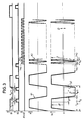
Bei Ausführung des Verfahrens nach Figur 3 erfolgt eine Auswertung der dem Gleichfeld entsprechenden Anteile entsprechend dem Verfahren nach Anspruch 1 wie unmittelbar aus Figur 3 ersichtlich.When the method according to FIG. 3 is carried out, the portions corresponding to the constant field are evaluated in accordance with the method according to
Die Auswertung des dem Wechselfeld entsprechenden Anteils erfolgt vereinfacht gemäß
(Up + uw)tw1 - (Up - uw)tw2 = 2uw
Der Umschalter 13 wird ebenso betätigt wie bei dem Verfahren nach Anspruch 1.The portion corresponding to the alternating field is evaluated in a simplified manner in accordance with
(U p + u w ) tw1 - (U p - u w ) tw2 = 2u w
The
Claims (10)
Applications Claiming Priority (2)
| Application Number | Priority Date | Filing Date | Title |
|---|---|---|---|
| DE19873728342 DE3728342A1 (en) | 1987-08-25 | 1987-08-25 | METHOD FOR GENERATING A SIGNAL THAT MEANS THE CURRENT STRENGTH OF A FLOWING, ELECTRICALLY CONDUCTIVE MEDIUM, AND CIRCUIT ARRANGEMENTS FOR IMPLEMENTING THE METHOD |
| DE3728342 | 1987-08-25 |
Publications (3)
| Publication Number | Publication Date |
|---|---|
| EP0304774A2 true EP0304774A2 (en) | 1989-03-01 |
| EP0304774A3 EP0304774A3 (en) | 1992-01-15 |
| EP0304774B1 EP0304774B1 (en) | 1994-06-29 |
Family
ID=6334447
Family Applications (1)
| Application Number | Title | Priority Date | Filing Date |
|---|---|---|---|
| EP88113286A Expired - Lifetime EP0304774B1 (en) | 1987-08-25 | 1988-08-16 | Method for generating a signal corresponding to the flow rate of a flowing conductive medium |
Country Status (2)
| Country | Link |
|---|---|
| EP (1) | EP0304774B1 (en) |
| DE (2) | DE3728342A1 (en) |
Cited By (5)
| Publication number | Priority date | Publication date | Assignee | Title |
|---|---|---|---|---|
| EP0521448A2 (en) * | 1991-07-04 | 1993-01-07 | Fischer & Porter GmbH | Circuit for the determination of errors in a magnetic-inductive flowmeter arrangement |
| EP0416866B1 (en) * | 1989-09-07 | 1996-05-01 | Kabushiki Kaisha Toshiba | Electromagnetic flowmeter utilizing magnetic fields of a plurality of frequencies |
| EP0730139A3 (en) * | 1995-03-02 | 1997-02-26 | Yokogawa Electric Corp | Electromagnetic flowmeter |
| EP0791806A2 (en) * | 1996-02-26 | 1997-08-27 | Aichi Tokei Denki Co., Ltd. | Electromagnetic flow meter removing influence of fluctuation in direct-current offset voltage |
| CN103591991A (en) * | 2013-11-08 | 2014-02-19 | 上海大学 | Electromagnetic flow meter with fluid impedance measurement |
Citations (4)
| Publication number | Priority date | Publication date | Assignee | Title |
|---|---|---|---|---|
| DE2637307A1 (en) * | 1975-10-14 | 1977-04-28 | Fischer & Porter Co | ELECTROMAGNETIC FLOW METER |
| DE2557328A1 (en) * | 1975-12-19 | 1977-07-07 | Fischer & Porter Gmbh | Inductive flowmeter with pulsed DC excitation - has measurement tube with electrodes buried in insulating coating of tube for liquids. of any conductivity |
| CH634408A5 (en) * | 1977-10-05 | 1983-01-31 | Flowtec Ag | METHOD AND ARRANGEMENT FOR INDUCTIVE FLOW MEASUREMENT. |
| FR2589571A1 (en) * | 1985-10-31 | 1987-05-07 | Sereg Soc | ELECTROMAGNETIC FLOWMETER WITH MAGNETIC FIELD PULSE |
Family Cites Families (1)
| Publication number | Priority date | Publication date | Assignee | Title |
|---|---|---|---|---|
| DE2603694A1 (en) * | 1976-01-31 | 1977-08-04 | Rombach Johann Baptist | Electronic counter for summing pulsed measurement values - operates with sources giving measurement values in different ranges using clock and address generators with coupled astable flip flops |
-
1987
- 1987-08-25 DE DE19873728342 patent/DE3728342A1/en not_active Ceased
-
1988
- 1988-08-16 DE DE3850462T patent/DE3850462D1/en not_active Expired - Lifetime
- 1988-08-16 EP EP88113286A patent/EP0304774B1/en not_active Expired - Lifetime
Patent Citations (4)
| Publication number | Priority date | Publication date | Assignee | Title |
|---|---|---|---|---|
| DE2637307A1 (en) * | 1975-10-14 | 1977-04-28 | Fischer & Porter Co | ELECTROMAGNETIC FLOW METER |
| DE2557328A1 (en) * | 1975-12-19 | 1977-07-07 | Fischer & Porter Gmbh | Inductive flowmeter with pulsed DC excitation - has measurement tube with electrodes buried in insulating coating of tube for liquids. of any conductivity |
| CH634408A5 (en) * | 1977-10-05 | 1983-01-31 | Flowtec Ag | METHOD AND ARRANGEMENT FOR INDUCTIVE FLOW MEASUREMENT. |
| FR2589571A1 (en) * | 1985-10-31 | 1987-05-07 | Sereg Soc | ELECTROMAGNETIC FLOWMETER WITH MAGNETIC FIELD PULSE |
Cited By (8)
| Publication number | Priority date | Publication date | Assignee | Title |
|---|---|---|---|---|
| EP0416866B1 (en) * | 1989-09-07 | 1996-05-01 | Kabushiki Kaisha Toshiba | Electromagnetic flowmeter utilizing magnetic fields of a plurality of frequencies |
| EP0521448A2 (en) * | 1991-07-04 | 1993-01-07 | Fischer & Porter GmbH | Circuit for the determination of errors in a magnetic-inductive flowmeter arrangement |
| EP0521448A3 (en) * | 1991-07-04 | 1995-03-15 | Fischer & Porter Gmbh | Circuit for the determination of errors in a magnetic-inductive flowmeter arrangement |
| EP0730139A3 (en) * | 1995-03-02 | 1997-02-26 | Yokogawa Electric Corp | Electromagnetic flowmeter |
| EP0791806A2 (en) * | 1996-02-26 | 1997-08-27 | Aichi Tokei Denki Co., Ltd. | Electromagnetic flow meter removing influence of fluctuation in direct-current offset voltage |
| EP0791806A3 (en) * | 1996-02-26 | 1998-02-04 | Aichi Tokei Denki Co., Ltd. | Electromagnetic flow meter removing influence of fluctuation in direct-current offset voltage |
| CN103591991A (en) * | 2013-11-08 | 2014-02-19 | 上海大学 | Electromagnetic flow meter with fluid impedance measurement |
| CN103591991B (en) * | 2013-11-08 | 2016-08-17 | 上海大学 | The electromagnetic flowmeter measured with fluid impedance |
Also Published As
| Publication number | Publication date |
|---|---|
| DE3728342A1 (en) | 1989-03-09 |
| EP0304774A3 (en) | 1992-01-15 |
| EP0304774B1 (en) | 1994-06-29 |
| DE3850462D1 (en) | 1994-08-04 |
Similar Documents
| Publication | Publication Date | Title |
|---|---|---|
| DE69532630T2 (en) | Magnetic-inductive flowmeter | |
| EP1817553A1 (en) | Method for monitoring a magnetically inductive flow measuring sensor | |
| EP1584902B1 (en) | Electromagnetic flowmeter and method for operating an electromagnetic flowmeter | |
| DE3133019A1 (en) | PERFORMANCE MEASURING DEVICE | |
| DE112013002522T5 (en) | Magnetic element control device, method for controlling a magnetic device and magnetic detection device | |
| DE3829564C2 (en) | Method for generating a signal corresponding to the current strength of a flowing, electrically conductive medium in an electromagnetic flow meter | |
| DE2846538A1 (en) | HEAT METER | |
| EP0304774A2 (en) | Method for generating a signal corresponding to the flow rate of a flowing conductive medium | |
| DE2634425A1 (en) | METHOD AND DEVICE FOR MEASURING THE POSITION OF A MAGNETIC ROD | |
| DE2837113C2 (en) | ||
| DE3525413A1 (en) | ELECTROMAGNETIC FLOW METER | |
| CH370154A (en) | Device for detecting electrical variables of the excitation circuit of electrical machines, in particular synchronous machines, in which a DC exciter winding is excited by the rotating armature of an AC exciter machine via rotating rectifiers | |
| EP0543053A1 (en) | Circuit arrangement for a device to measure the flow rate of a fluid containing electrical charges | |
| DE2240054C3 (en) | Inductive flow meter | |
| EP1541973B1 (en) | Electromagnetic flowmeter and measuring method for an electromagnetic flowmeter | |
| DE102014216404B4 (en) | Current measuring device and method for detecting a current | |
| DE3148007C2 (en) | ||
| DE4221057C2 (en) | Method of recording electrical energy consumption | |
| DE102016124977B4 (en) | Method for operating a magnetic-inductive flow measuring device and such a flow measuring device | |
| DE3625011C2 (en) | ||
| DE3147819A1 (en) | Detection of the vehicle position by counting grooves | |
| US3739274A (en) | Direct current measuring system | |
| DE60002706T2 (en) | CURRENT SENSOR | |
| DE19843133A1 (en) | Method of measuring the speed of an induction machine | |
| EP0501200B1 (en) | Electrical installation having compensation principle current sensors |
Legal Events
| Date | Code | Title | Description |
|---|---|---|---|
| PUAI | Public reference made under article 153(3) epc to a published international application that has entered the european phase |
Free format text: ORIGINAL CODE: 0009012 |
|
| AK | Designated contracting states |
Kind code of ref document: A2 Designated state(s): CH DE FR GB LI NL |
|
| PUAL | Search report despatched |
Free format text: ORIGINAL CODE: 0009013 |
|
| AK | Designated contracting states |
Kind code of ref document: A3 Designated state(s): CH DE FR GB LI NL |
|
| 17P | Request for examination filed |
Effective date: 19920519 |
|
| 17Q | First examination report despatched |
Effective date: 19920818 |
|
| GRAA | (expected) grant |
Free format text: ORIGINAL CODE: 0009210 |
|
| AK | Designated contracting states |
Kind code of ref document: B1 Designated state(s): CH DE FR GB LI NL |
|
| REF | Corresponds to: |
Ref document number: 3850462 Country of ref document: DE Date of ref document: 19940804 |
|
| ET | Fr: translation filed | ||
| GBT | Gb: translation of ep patent filed (gb section 77(6)(a)/1977) |
Effective date: 19941006 |
|
| PLBE | No opposition filed within time limit |
Free format text: ORIGINAL CODE: 0009261 |
|
| STAA | Information on the status of an ep patent application or granted ep patent |
Free format text: STATUS: NO OPPOSITION FILED WITHIN TIME LIMIT |
|
| 26N | No opposition filed | ||
| REG | Reference to a national code |
Ref country code: GB Ref legal event code: IF02 |
|
| PGFP | Annual fee paid to national office [announced via postgrant information from national office to epo] |
Ref country code: GB Payment date: 20050808 Year of fee payment: 18 |
|
| PGFP | Annual fee paid to national office [announced via postgrant information from national office to epo] |
Ref country code: NL Payment date: 20050812 Year of fee payment: 18 Ref country code: FR Payment date: 20050812 Year of fee payment: 18 |
|
| PGFP | Annual fee paid to national office [announced via postgrant information from national office to epo] |
Ref country code: CH Payment date: 20060815 Year of fee payment: 19 |
|
| PG25 | Lapsed in a contracting state [announced via postgrant information from national office to epo] |
Ref country code: NL Free format text: LAPSE BECAUSE OF NON-PAYMENT OF DUE FEES Effective date: 20070301 |
|
| GBPC | Gb: european patent ceased through non-payment of renewal fee |
Effective date: 20060816 |
|
| NLV4 | Nl: lapsed or anulled due to non-payment of the annual fee |
Effective date: 20070301 |
|
| REG | Reference to a national code |
Ref country code: FR Ref legal event code: ST Effective date: 20070430 |
|
| PGFP | Annual fee paid to national office [announced via postgrant information from national office to epo] |
Ref country code: DE Payment date: 20070822 Year of fee payment: 20 |
|
| REG | Reference to a national code |
Ref country code: CH Ref legal event code: PFA Owner name: FISCHER & PORTER GMBH Free format text: FISCHER & PORTER GMBH#DRANSFELDER STRASSE 2#GOETTINGEN (DE) -TRANSFER TO- FISCHER & PORTER GMBH#DRANSFELDER STRASSE 2#GOETTINGEN (DE) |
|
| PG25 | Lapsed in a contracting state [announced via postgrant information from national office to epo] |
Ref country code: GB Free format text: LAPSE BECAUSE OF NON-PAYMENT OF DUE FEES Effective date: 20060816 |
|
| REG | Reference to a national code |
Ref country code: CH Ref legal event code: PL |
|
| PG25 | Lapsed in a contracting state [announced via postgrant information from national office to epo] |
Ref country code: FR Free format text: LAPSE BECAUSE OF NON-PAYMENT OF DUE FEES Effective date: 20060831 Ref country code: LI Free format text: LAPSE BECAUSE OF NON-PAYMENT OF DUE FEES Effective date: 20070831 Ref country code: CH Free format text: LAPSE BECAUSE OF NON-PAYMENT OF DUE FEES Effective date: 20070831 |