EP0304407B1 - Isolated insertion chute for suction-operated garbage disposal systems - Google Patents
Isolated insertion chute for suction-operated garbage disposal systems Download PDFInfo
- Publication number
- EP0304407B1 EP0304407B1 EP88850265A EP88850265A EP0304407B1 EP 0304407 B1 EP0304407 B1 EP 0304407B1 EP 88850265 A EP88850265 A EP 88850265A EP 88850265 A EP88850265 A EP 88850265A EP 0304407 B1 EP0304407 B1 EP 0304407B1
- Authority
- EP
- European Patent Office
- Prior art keywords
- chute
- chute portion
- flange
- connecting flange
- branching
- Prior art date
- Legal status (The legal status is an assumption and is not a legal conclusion. Google has not performed a legal analysis and makes no representation as to the accuracy of the status listed.)
- Expired
Links
- 238000003780 insertion Methods 0.000 title claims description 52
- 230000037431 insertion Effects 0.000 title claims description 52
- 238000010068 moulding (rubber) Methods 0.000 claims description 11
- 238000007789 sealing Methods 0.000 claims description 7
- 230000005540 biological transmission Effects 0.000 claims description 4
- 230000007704 transition Effects 0.000 claims description 4
- 229910000831 Steel Inorganic materials 0.000 claims description 3
- 239000010959 steel Substances 0.000 claims description 3
- 239000004033 plastic Substances 0.000 claims description 2
- 230000008439 repair process Effects 0.000 description 9
- 238000012423 maintenance Methods 0.000 description 6
- 238000004519 manufacturing process Methods 0.000 description 3
- 238000005266 casting Methods 0.000 description 2
- 230000001419 dependent effect Effects 0.000 description 2
- 238000013461 design Methods 0.000 description 2
- 230000001154 acute effect Effects 0.000 description 1
- 238000009412 basement excavation Methods 0.000 description 1
- 230000008901 benefit Effects 0.000 description 1
- 230000015572 biosynthetic process Effects 0.000 description 1
- 238000004891 communication Methods 0.000 description 1
- 238000005520 cutting process Methods 0.000 description 1
- 229920006333 epoxy cement Polymers 0.000 description 1
- 238000000034 method Methods 0.000 description 1
- 238000012986 modification Methods 0.000 description 1
- 230000004048 modification Effects 0.000 description 1
- 238000012545 processing Methods 0.000 description 1
Images


Classifications
-
- E—FIXED CONSTRUCTIONS
- E04—BUILDING
- E04F—FINISHING WORK ON BUILDINGS, e.g. STAIRS, FLOORS
- E04F17/00—Vertical ducts; Channels, e.g. for drainage
- E04F17/10—Arrangements in buildings for the disposal of refuse
- E04F17/12—Chutes
-
- B—PERFORMING OPERATIONS; TRANSPORTING
- B65—CONVEYING; PACKING; STORING; HANDLING THIN OR FILAMENTARY MATERIAL
- B65F—GATHERING OR REMOVAL OF DOMESTIC OR LIKE REFUSE
- B65F5/00—Gathering or removal of refuse otherwise than by receptacles or vehicles
- B65F5/005—Gathering or removal of refuse otherwise than by receptacles or vehicles by pneumatic means, e.g. by suction
Definitions
- the invention generally relates to isolated insertion chutes which at spaced intervals are connected to an underground suction conveying conduit communicating with a refuse suction system, and more specifically refers to a device constituting an association of such isolated insertion chutes with the suction conveying conduit and of the kind indicated in the preamble of claim 1.
- FR-A-2 157 995 discloses a device of this kind specifically employed in connection with insertion chutes installed in buildings, including one insertion opening for each storey and associated with the suction conveying conduit within the basement of the building.
- Each such insertion chute comprises an upper portion containing the insertion openings and a lower portion being vertically slidably guided on the upper chute portion and being slidably received in a branching extended from the suction conveying conduit.
- the slidable lower chute portion acts as a valve controlling the communication of the insertion chute with the suction conveying conduit and is at its upper end provided with a flange intended to rest on a flange at the upper end of the branching when the valve is in its closed position.
- the prior art device is specifically intended for use by insertion chutes installed within buildings and connected to a suction conveying conduit within the basement of the building, which means that there is no need for any specific arrangement for facilitating repair and service of the valve and its drive means.
- a specific problem is encountered with isolated insertion chutes of the kind discussed above, where the connection - possibly through the valve means provided at the lower end of the the insertion chute - to the underground collection conduit is provided below the ground surface immediately adjacent the collecting conduit, as illustrated in Swedish patent specification No. 7302382-2 (publication No. 381 021).
- the lower portion of the insertion chute is enclosed in a chamber provided below the ground surface and being accessible from the ground surface for instance through a hatch.
- This solution causes substantial costs both for the additional digging or dredging required at the locations where insertion chutes are to be positioned, in order to also provide sufficient space for a chamber having such dimensions that personnel without difficulty may get down into the chamber to perform necessary work, and for the work performed in connection with casting the chamber in itself.
- the maintenance or repair work is also inconvenient and troublesome, and this is true even if the chamber is properly dimensioned, and particular problems arise especially if parts cannot be repaired on location but must be removed for repair or must be exchanged.
- the principal object of the present invention is to provide a device of the above indicated kind, by means of which the above described disadvantages in connection with the prior art devices may be eliminated, while the reliable operation of the insertion chute must also be maintained.
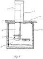
- Fig. 1 schematically illustrates an example of the previously known technique disclosed in Swedish patent specification No. 7302382-2.
- This known system comprises a column 1 positioned above the ground surface and having a sluice-like refuse receiving means 2.
- the sluice-like refuse receiving means 2 is provided adjacent the upper end of an insertion chute 3 which extends down through the column 1 and into a chamber 4 provided below the ground surface.
- the chute 3 is connected to a collecting conduit 6 which in turn is connected to a refuse suction conduit system in which, at least during certain periods of time, a suction-produced conveying air-stream is flowing.
- a suction-produced conveying air-stream is flowing.
- a valve means 5 may be provided for selectively closing and opening the lower end of the chute 3.
- the chamber 4 is provided with a hatch 7 through which the chamber is accessible for maintenance and repair work.
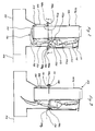
- Fig. 2 the insertion chute according to the invention is illustrated partially in section, whereby the valve operating means are not illustrated in section.
- Fig. 2 clearly illustrates that the insertion chute 103 according to the invention comprises an upper chute portion 103a and a lower chute portion 103b which through a flange joint 108 are connected to the branching 109 of a T-piece 110 connected to the collecting conduit 106.
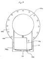
- Figs. 2 and 4 illustrate that the upper portion 103a of the insertion chute 103 is substantially cylindrical and is provided at its lower end with a connecting flange 108a having bores 108b provided therein for receiving mounting bolts 108c.
- the upper end of the upper chute portion 103a is intended to communicate with a sluice-like receiving means (not shown), for instance of the kind disclosed and illustrated in the above mentioned Swedish patent specification.
- a substantially rectangular, box-like superstructure 111 is welded to the exterior of the upper chute portion 103a, and this superstructure is intended to receive the valve operating means 112 which, in the illustrated embodiment, consists of a cylinder, preferably a pneumatic cylinder.
- the rear end wall of the cylinder 112 is pivotally journalled to the upper chute portion 103a and its free piston rod end is pivotally connected to a rotary transmission link 113 which is also rotatably journalled in the upper chute portion 103a.
- a valve operating rod 114 is also pivotally connected to the rotary transmission link, as will be described more closely below.
- the superstructure 111 is provided with a lid 115 at one of its sides, and through this lid it is possible to get access to the valve operating means for maintenance and repair thereof and of the control equipment for the valve means which is also provided in the superstructure 111 but which is not described closely herein since it does not form any part of the invention.
- a projecting portion 108d of the flange 108a of the upper chute portion 103a forms the bottom of the superstructure 111 and is also provided with a recess 111a through which the operating rod 114 is extended and through which wires may also be passed.
- the recess also serves to ventilate the interior of the superstructure to the environment.
- Figs. 2 and 5 illustrate that the lower portion 103b of the insertion chute 103 is also substantially cylindrical. However, it has as slightly larger diameter than that of the upper portion 103a, and the purpose thereof is to guarantee that manufacturing tolerances do not cause the formation of any steps at the transition between the upper and lower portions, on which steps refuse otherwise might get stuck.
- the lower portion 103b of the chute is also, at its upper end, provided with a connecting flange 108e having bores 108b which in the assembled condition coincide with those of the connecting flange of the upper chute portion 103a, so that the mounting bolts 108a may be passed through said bores.
- the flange 108e of the lower chute portion 103b is also provided with a projecting portion 108f having an elongated groove 111b through which the operating rod 114 may be passed, whereby the length of the groove at least corresponds to the movement of the operating rod 114 when operating the valve means 116 consisting of a flap 117 pivotally journalled at the lower end of the lower chute portion 103b.
- the lower end of the operating rod 114 engages a lever 118 attached to the flap, for manoeuvring the flap 117 between its closed and opened conditions (compare with Figs. 2 and 3).
- a rubber sealing ring 119 is provided around the lower end of the lower chute portion 103b, and the flap 117 sealingly engages this sealing ring when the flap is in its closed condition (see Fig. 2).
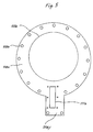
- Figs. 2 and 3 illustrate that the lower portion 103b of the chute, the valve 116 and the operating rod 114 are received in the branching 109 of the T-piece 110, said branching also having a substantially cylindrical shape, as is clear from Fig. 6, but having a diameter which is so much larger than that of the lower chute portion that the lower chute portion 103b may be inserted therein.
- the branching is also provided with a portion 109a being substantially rectangular in cross-section and projecting from the cylindrical portion for receiving the operating rod 114 and the valve means 116.
- the branching 109 comprises, at its upper end, a flange 108g having bolt bores 108b and a projecting portion 108h, said projecting portion 108h being provided with a groove 111c being open into the cylindrical portion of the branching and serving as a passage for the operating rod 114.
- a seal unit 120 is attached by means of screws to the upper side of the flange 108e and is intended to seal the passage of the operating rod 114 through the groove 111b in the flange 108e of the lower chute portion 103b against the conveying air-stream in the collecting conduit.
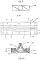
- Figs. 8a and 8b illustrate that the seal unit 120 consits of a rectangular plate 121 which at its underside is provided with a gasket 122 which is bonded thereto and which is provided with a longitudinal groove 123 corresponding to and in the assembled condition coinciding with the groove 111b of the flange 108e.
- two rubber mouldings 124 are clamped by means of flat bars 125 and mounting screws 126, said rubber mouldings each having a width substantially exceeding half the width of the plate 121 so that the free edges of the rubber mouldings 124 sealingly engage each other to form an inverted V.
- filling members 127 for instance of epoxy cement, are provided which may suitably be attached by bonding or screwing from below and in a manner not illustrated in detail.
- the seal unit 120 is attached to the flange 108e by means of mounting screws 128 which simultaneously provide additional clamping of the rubber mouldings 124.
- Fig. 7 and to a certain extent also Figs. 2 and 3 illustrate that the operating rod 114 is manufactured from flat bar steel or any other correspondingly shaped blank of for instance plastic, from which two opposite longitudinal edges have been chamfered by cutting off the opposite sides thereof along the length of the operating rod which will be engaging the rubber mouldings 124 of the seal unit 120 during operation of the valve.
- each side is cut off from one longitudinal edge and approximately to the longitudinal center line of the opposite long side where the chamfer is rounded towards the long side.
- said portion of the operating rod 114 will be formed as a rhomboid in section.
- the above described chamfering or cutting-off of the longitudinal edges results in a rhomboid shape having an acute angle of approximately 30°, whereby an excellent sealing is continuously maintained between the operating rod 114 and the rubber mouldings 124 during the valve operating movement of the operating rod.
- valve means 116 is self-locking in its closed position due to the fact that the extended center line of the operating rod 114 towards the end of the closing movement passes the pivot axle of the pivot-transmission link 113 so that the force applied by the seal pressure and refuse collected on the valve member 117, through the lever 118 and the operating rod 114 serves to maintain the pivot-transmission link 113 in the corresponding position, abutting a stop 113b.
- a corresponding stop 113a is provided for stopping the pivot-transmission link 113 in the fully open position of the valve means 116.
- Figs. 2 and 3 illustrate that the insertion chute is assembled by inserting the lower chute portion 103b with the operating rod 114 and the valve means 116 into the branching 109 so that its flange 108e abuts the flange 108f of the branching 109.
- the connection between the flanges is sealed by bonding a gasket 131 to the underside of the flange 108e of the lower chute portion 103b.
- the upper chute portion 103a is placed on the lower chute portion 103b with its flange 108a abutting the flange 108e of the lower chute portion, whereupon the flange joint 108 is completed by inserting and tightening the connecting bolts 108c so that the lower chute portion 103b is clamped between the upper chute portion 103a and the branching 109.
- a gasket 131 may also be provided on the underside of the flange 108a of the upper chute portion 103a, for sealing between the upper and lower chute portions.
- the operating rod 114 is connected to the pivot-transmission link 113 and this work may be easily performed when the lid 115 has been opened.
- the lower chute portion 103b and the valve means 116 may then be lifted off as a unit whereby repair work may be performed on location or alternatively a replacement unit may be assembled so that the insertion chute may immediately come into use again. Due to the relatively simple removal of the complete insertion chute 103 it is also easy to take measures in case of clogging and obstruction.
- Fig. 9 illustrates an alternative embodiment of the insertion chute according to the invention, said insertion chute 203 being built as a unit, i.e. the upper portion 203a and the lower portion 203b of the insertion chute are integral.
- the flange joint 208 is formed by this single connecting flange 208a on the insertion chute 203 and by the connecting flange 208g of the branching.
- the connecting flange 208g of the branching is preferably identical to that of the first embodiment, while the connecting flange 208a may be either identical to the connecting flange 108e of the first embodiment or may alternatively be slightly modified to resemble the connecting flange 108a of the first embodiment, in order to form also a portion of the bottom of the superstructure. It is vital that the connecting flange 208a corresponds to the connecting flange 108e of the first embodiment as regards the sealing against the branching and as regards the sealed through-passage of the operating rod. The remaining details of this second embodiment are identical to those of the first embodiment.
- the advantage of the embodiment of the insertion chute illustrated in Fig. 9 is that the manufacturing thereof is substantially simplified which also means that the manufacturing costs may be kept low.
- the insertion chute of this design will be more difficult to handle, and for that reason the first embodiment, according to which the insertion chute may be divided, is preferred in the cases where it is desirable to perform work without using any lifting equipment.
- the portions of the insertion chute may be lifted off by two persons without the aid of any hoisting crane or the like.
- the insertion chute may also be performed without any valve means in applications where the service conditions are such that the valve means are not necessary, but the refuse may fall directly down into the collecting conduit.
- the portions may be quite cylindrical in shape.
Landscapes
- Engineering & Computer Science (AREA)
- Architecture (AREA)
- Civil Engineering (AREA)
- Structural Engineering (AREA)
- Chutes (AREA)
- Refuse Collection And Transfer (AREA)
- Lift Valve (AREA)
- Check Valves (AREA)
Description
- The invention generally relates to isolated insertion chutes which at spaced intervals are connected to an underground suction conveying conduit communicating with a refuse suction system, and more specifically refers to a device constituting an association of such isolated insertion chutes with the suction conveying conduit and of the kind indicated in the preamble of claim 1.
- FR-A-2 157 995 discloses a device of this kind specifically employed in connection with insertion chutes installed in buildings, including one insertion opening for each storey and associated with the suction conveying conduit within the basement of the building. Each such insertion chute comprises an upper portion containing the insertion openings and a lower portion being vertically slidably guided on the upper chute portion and being slidably received in a branching extended from the suction conveying conduit. The slidable lower chute portion acts as a valve controlling the communication of the insertion chute with the suction conveying conduit and is at its upper end provided with a flange intended to rest on a flange at the upper end of the branching when the valve is in its closed position.
- As mentioned above the prior art device is specifically intended for use by insertion chutes installed within buildings and connected to a suction conveying conduit within the basement of the building, which means that there is no need for any specific arrangement for facilitating repair and service of the valve and its drive means. However, a specific problem is encountered with isolated insertion chutes of the kind discussed above, where the connection - possibly through the valve means provided at the lower end of the the insertion chute - to the underground collection conduit is provided below the ground surface immediately adjacent the collecting conduit, as illustrated in Swedish patent specification No. 7302382-2 (publication No. 381 021). In order to permit access to such a collecting conduit in case it is clogged or obstructed close to the connecting point of the insertion chute or to permit maintenance, repair and possibly exchange of the valve means or parts thereof, the lower portion of the insertion chute is enclosed in a chamber provided below the ground surface and being accessible from the ground surface for instance through a hatch. This solution causes substantial costs both for the additional digging or dredging required at the locations where insertion chutes are to be positioned, in order to also provide sufficient space for a chamber having such dimensions that personnel without difficulty may get down into the chamber to perform necessary work, and for the work performed in connection with casting the chamber in itself. Naturally the maintenance or repair work is also inconvenient and troublesome, and this is true even if the chamber is properly dimensioned, and particular problems arise especially if parts cannot be repaired on location but must be removed for repair or must be exchanged.
- Thus, the principal object of the present invention is to provide a device of the above indicated kind, by means of which the above described disadvantages in connection with the prior art devices may be eliminated, while the reliable operation of the insertion chute must also be maintained.
- This object is attained by means of a device of the kind indicated in the characterizing portion of the enclosed claim 1.
- Preferred improvements and suitable embodiments of the invention are indicated in the dependent subclaims.
- With the purpose of exemplifying the invention an embodiment thereof is disclosed more closely below in connection with the enclosed drawings, in which:
- Fig. 1 illustrates a prior art insertion chute,
- Fig. 2 illustrates, partly in section, the device according to the present invention, with a valve means in its closed condition,
- Fig. 3 illustrates the device according to the present invention, in a view corresponding to that of Fig. 2, but with the valve means in its open condition,
- Fig. 4 illustrates, in a section along line A-A in Fig. 2, the upper portion of the chute with the valve operating means removed,
- Fig. 5 is a top view of the lower portion of the chute, without valve operating means and seal unit,
- Fig. 6 is a top view of the branching of the T-piece,
- Fig. 7 is an endview of the lower operating rod,
- Fig. 8a is a top elevation of the seal unit for the operating rod,
- Fig. 8b is a section along line B-B in Fig. 8a of the seal unit, and
- Fig. 9 illustrates an alternative embodiment of the device, in a view corresponding to that of Fig. 2.
- Fig. 1 schematically illustrates an example of the previously known technique disclosed in Swedish patent specification No. 7302382-2. This known system comprises a column 1 positioned above the ground surface and having a sluice-like
refuse receiving means 2. The sluice-likerefuse receiving means 2 is provided adjacent the upper end of aninsertion chute 3 which extends down through the column 1 and into achamber 4 provided below the ground surface. In thechamber 4 thechute 3 is connected to acollecting conduit 6 which in turn is connected to a refuse suction conduit system in which, at least during certain periods of time, a suction-produced conveying air-stream is flowing. At the lower end of the insertion chute, i.e. at its connection to the collecting conduit 6 a valve means 5 may be provided for selectively closing and opening the lower end of thechute 3. In the ground-level plan thechamber 4 is provided with ahatch 7 through which the chamber is accessible for maintenance and repair work. This design of the system causes the above discussed problems and disadvantages regarding excavation for and casting of thechamber 4 and regarding the inconvenient and troublesome maintenance and repair work. - In Fig. 2 the insertion chute according to the invention is illustrated partially in section, whereby the valve operating means are not illustrated in section. Fig. 2 clearly illustrates that the
insertion chute 103 according to the invention comprises anupper chute portion 103a and alower chute portion 103b which through aflange joint 108 are connected to the branching 109 of a T-piece 110 connected to thecollecting conduit 106. - Figs. 2 and 4 illustrate that the
upper portion 103a of theinsertion chute 103 is substantially cylindrical and is provided at its lower end with a connectingflange 108a having bores 108b provided therein for receivingmounting bolts 108c. The upper end of theupper chute portion 103a is intended to communicate with a sluice-like receiving means (not shown), for instance of the kind disclosed and illustrated in the above mentioned Swedish patent specification. A substantially rectangular, box-like superstructure 111 is welded to the exterior of theupper chute portion 103a, and this superstructure is intended to receive thevalve operating means 112 which, in the illustrated embodiment, consists of a cylinder, preferably a pneumatic cylinder. The rear end wall of thecylinder 112 is pivotally journalled to theupper chute portion 103a and its free piston rod end is pivotally connected to arotary transmission link 113 which is also rotatably journalled in theupper chute portion 103a. Avalve operating rod 114 is also pivotally connected to the rotary transmission link, as will be described more closely below. Thesuperstructure 111 is provided with alid 115 at one of its sides, and through this lid it is possible to get access to the valve operating means for maintenance and repair thereof and of the control equipment for the valve means which is also provided in thesuperstructure 111 but which is not described closely herein since it does not form any part of the invention. A projectingportion 108d of theflange 108a of theupper chute portion 103a forms the bottom of thesuperstructure 111 and is also provided with arecess 111a through which theoperating rod 114 is extended and through which wires may also be passed. The recess also serves to ventilate the interior of the superstructure to the environment. - Figs. 2 and 5 illustrate that the
lower portion 103b of theinsertion chute 103 is also substantially cylindrical. However, it has as slightly larger diameter than that of theupper portion 103a, and the purpose thereof is to guarantee that manufacturing tolerances do not cause the formation of any steps at the transition between the upper and lower portions, on which steps refuse otherwise might get stuck. Thelower portion 103b of the chute is also, at its upper end, provided with a connectingflange 108e having bores 108b which in the assembled condition coincide with those of the connecting flange of theupper chute portion 103a, so that themounting bolts 108a may be passed through said bores. At a position corresponding to that of the projectingportion 108d of theflange 108a of theupper chute portion 103a theflange 108e of thelower chute portion 103b is also provided with a projectingportion 108f having an elongated groove 111b through which theoperating rod 114 may be passed, whereby the length of the groove at least corresponds to the movement of theoperating rod 114 when operating the valve means 116 consisting of aflap 117 pivotally journalled at the lower end of thelower chute portion 103b. The lower end of theoperating rod 114 engages alever 118 attached to the flap, for manoeuvring theflap 117 between its closed and opened conditions (compare with Figs. 2 and 3). Arubber sealing ring 119 is provided around the lower end of thelower chute portion 103b, and theflap 117 sealingly engages this sealing ring when the flap is in its closed condition (see Fig. 2). - Figs. 2 and 3 illustrate that the
lower portion 103b of the chute, thevalve 116 and theoperating rod 114 are received in the branching 109 of the T-piece 110, said branching also having a substantially cylindrical shape, as is clear from Fig. 6, but having a diameter which is so much larger than that of the lower chute portion that thelower chute portion 103b may be inserted therein. The branching is also provided with aportion 109a being substantially rectangular in cross-section and projecting from the cylindrical portion for receiving theoperating rod 114 and the valve means 116. Like the chute portions the branching 109 comprises, at its upper end, aflange 108g havingbolt bores 108b and a projectingportion 108h, said projectingportion 108h being provided with agroove 111c being open into the cylindrical portion of the branching and serving as a passage for theoperating rod 114. - A
seal unit 120 is attached by means of screws to the upper side of theflange 108e and is intended to seal the passage of theoperating rod 114 through the groove 111b in theflange 108e of thelower chute portion 103b against the conveying air-stream in the collecting conduit. Figs. 8a and 8b illustrate that theseal unit 120 consits of arectangular plate 121 which at its underside is provided with agasket 122 which is bonded thereto and which is provided with alongitudinal groove 123 corresponding to and in the assembled condition coinciding with the groove 111b of theflange 108e. On the upper side of theplate 121, on each side of thegroove 123, tworubber mouldings 124 are clamped by means offlat bars 125 and mountingscrews 126, said rubber mouldings each having a width substantially exceeding half the width of theplate 121 so that the free edges of therubber mouldings 124 sealingly engage each other to form an inverted V. In order to seal the space between therubber mouldings 124 at their shortedges filling members 127, for instance of epoxy cement, are provided which may suitably be attached by bonding or screwing from below and in a manner not illustrated in detail. Theseal unit 120 is attached to theflange 108e by means of mountingscrews 128 which simultaneously provide additional clamping of therubber mouldings 124. - Fig. 7 and to a certain extent also Figs. 2 and 3 illustrate that the
operating rod 114 is manufactured from flat bar steel or any other correspondingly shaped blank of for instance plastic, from which two opposite longitudinal edges have been chamfered by cutting off the opposite sides thereof along the length of the operating rod which will be engaging therubber mouldings 124 of theseal unit 120 during operation of the valve. In cross-section, each side is cut off from one longitudinal edge and approximately to the longitudinal center line of the opposite long side where the chamfer is rounded towards the long side. Through this processing said portion of theoperating rod 114 will be formed as a rhomboid in section. As an example it may also be mentioned that if the dimensions of the flat bar steel is 20 x 70 mm the above described chamfering or cutting-off of the longitudinal edges results in a rhomboid shape having an acute angle of approximately 30°, whereby an excellent sealing is continuously maintained between theoperating rod 114 and therubber mouldings 124 during the valve operating movement of the operating rod. - The function of the insertion chute is not discussed in detail herein, but in this regard reference is made to for instance the above mentioned Swedish patent No. 7302392-2 and especially regarding the operation of the valve dependent upon different factors. In this connection it should only be mentioned that the valve means 116 is self-locking in its closed position due to the fact that the extended center line of the
operating rod 114 towards the end of the closing movement passes the pivot axle of the pivot-transmission link 113 so that the force applied by the seal pressure and refuse collected on thevalve member 117, through thelever 118 and theoperating rod 114 serves to maintain the pivot-transmission link 113 in the corresponding position, abutting a stop 113b. Due to this fact theoperating cylinder 112 does not have to be continuously pressurized, and pressure will only have to be applied when the valve is to be operated. A corresponding stop 113a is provided for stopping the pivot-transmission link 113 in the fully open position of the valve means 116. - Figs. 2 and 3 illustrate that the insertion chute is assembled by inserting the
lower chute portion 103b with the operatingrod 114 and the valve means 116 into the branching 109 so that itsflange 108e abuts theflange 108f of the branching 109. Preferably the connection between the flanges is sealed by bonding agasket 131 to the underside of theflange 108e of thelower chute portion 103b. Subsequently theupper chute portion 103a is placed on thelower chute portion 103b with itsflange 108a abutting theflange 108e of the lower chute portion, whereupon the flange joint 108 is completed by inserting and tightening the connectingbolts 108c so that thelower chute portion 103b is clamped between theupper chute portion 103a and the branching 109. Possibly agasket 131 may also be provided on the underside of theflange 108a of theupper chute portion 103a, for sealing between the upper and lower chute portions. Finally the operatingrod 114 is connected to the pivot-transmission link 113 and this work may be easily performed when thelid 115 has been opened. - It will be appreciated that due to the fact that the branching 109 has such a length that the flange joint 108 will be positioned just above the ground surface, as indicated at 130 in Fig. 3, repair and maintenance work is easily performed on all components or parts related to the insertion chute. When work is to be performed on the operating means 112, the pivot-
transmission link 113 or the control equipment it is only necessary to open thelid 115. If, on the other hand, work is to be performed on the valve means 116 or itsseal 119 the operatingrod 114 is fist disconnected from the pivot-transmission link 113 and then thebolts 108c of the flange joint 108 are unscrewed, whereupon theupper chute portion 103a may be lifted off. Thelower chute portion 103b and the valve means 116 may then be lifted off as a unit whereby repair work may be performed on location or alternatively a replacement unit may be assembled so that the insertion chute may immediately come into use again. Due to the relatively simple removal of thecomplete insertion chute 103 it is also easy to take measures in case of clogging and obstruction. - Fig. 9 illustrates an alternative embodiment of the insertion chute according to the invention, said
insertion chute 203 being built as a unit, i.e. theupper portion 203a and the lower portion 203b of the insertion chute are integral. In this case only one connectingflange 208a is provided on the exterior of theinsertion chute 203 at the transition between the upper andlower portions 203a and 203b respectively of the insertion chute. In this embodiment the flange joint 208 is formed by this single connectingflange 208a on theinsertion chute 203 and by the connecting flange 208g of the branching. The connecting flange 208g of the branching is preferably identical to that of the first embodiment, while the connectingflange 208a may be either identical to the connectingflange 108e of the first embodiment or may alternatively be slightly modified to resemble the connectingflange 108a of the first embodiment, in order to form also a portion of the bottom of the superstructure. It is vital that the connectingflange 208a corresponds to the connectingflange 108e of the first embodiment as regards the sealing against the branching and as regards the sealed through-passage of the operating rod. The remaining details of this second embodiment are identical to those of the first embodiment. - The advantage of the embodiment of the insertion chute illustrated in Fig. 9 is that the manufacturing thereof is substantially simplified which also means that the manufacturing costs may be kept low. On the other hand the insertion chute of this design will be more difficult to handle, and for that reason the first embodiment, according to which the insertion chute may be divided, is preferred in the cases where it is desirable to perform work without using any lifting equipment. According to this first embodiment where the insertion chute may be divided, the portions of the insertion chute may be lifted off by two persons without the aid of any hoisting crane or the like.
- Although preferred embodiments of the present invention have been illustrated and disclosed herein it should be obvious that further modifications may be carried out by men skilled in the art without departing from the scope of the invention. As an example the insertion chute may also be performed without any valve means in applications where the service conditions are such that the valve means are not necessary, but the refuse may fall directly down into the collecting conduit. In this embodiment the portions may be quite cylindrical in shape. Thus, the scope of the invention shall only be determined by the enclosed patent claims.
Claims (10)
Applications Claiming Priority (2)
| Application Number | Priority Date | Filing Date | Title |
|---|---|---|---|
| SE8703188A SE461211B (en) | 1987-08-17 | 1987-08-17 | DEVICE INSERT SHAKES FOR A WASTE CLEANER |
| SE8703188 | 1987-08-17 |
Publications (3)
| Publication Number | Publication Date |
|---|---|
| EP0304407A2 EP0304407A2 (en) | 1989-02-22 |
| EP0304407A3 EP0304407A3 (en) | 1989-12-06 |
| EP0304407B1 true EP0304407B1 (en) | 1992-05-20 |
Family
ID=20369303
Family Applications (1)
| Application Number | Title | Priority Date | Filing Date |
|---|---|---|---|
| EP88850265A Expired EP0304407B1 (en) | 1987-08-17 | 1988-08-10 | Isolated insertion chute for suction-operated garbage disposal systems |
Country Status (8)
| Country | Link |
|---|---|
| US (1) | US5004377A (en) |
| EP (1) | EP0304407B1 (en) |
| JP (1) | JP2778718B2 (en) |
| DE (1) | DE3871284D1 (en) |
| DK (1) | DK169516B1 (en) |
| ES (1) | ES2033463T3 (en) |
| SE (1) | SE461211B (en) |
| WO (1) | WO1989001450A1 (en) |
Families Citing this family (9)
| Publication number | Priority date | Publication date | Assignee | Title |
|---|---|---|---|---|
| KR100222271B1 (en) * | 1995-09-22 | 1999-10-01 | 한스 스트롬 | Inserting chute of separating type |
| KR19980077546A (en) * | 1997-04-21 | 1998-11-16 | 한스 스트롬 | Waste Disposal Method and Device |
| SE521271C2 (en) * | 2001-06-20 | 2003-10-14 | Centralsug Ab | Inset shaft with upper and lower section |
| SE532516C2 (en) * | 2008-06-04 | 2010-02-16 | Logiwaste Ab | Shafts for collection plant and connected unit for shafts with detachably mounted unit including i.a. a valve member |
| KR100896398B1 (en) * | 2009-02-06 | 2009-05-08 | 코오롱건설주식회사 | The volume-limited garbage inlet of the garbage collection system |
| KR100916052B1 (en) * | 2009-02-24 | 2009-09-08 | 코오롱건설주식회사 | Waste Discharge Valve in Vacuum Transfer Garbage Collection System |
| KR101103760B1 (en) * | 2009-08-03 | 2012-01-11 | (주)유로파 | Basket valve opening and closing structure of automatic garbage collection facility |
| KR101103763B1 (en) * | 2009-08-03 | 2012-01-10 | (주)유로파 | Double door open / close discharge valve of automatic garbage collection facility |
| CN113003060B (en) * | 2021-02-24 | 2023-05-26 | 湖北帝成环卫科技有限公司 | Compression garbage truck back door headstock gear |
Family Cites Families (9)
| Publication number | Priority date | Publication date | Assignee | Title |
|---|---|---|---|---|
| FR655834A (en) * | 1928-05-25 | 1929-04-24 | Dumpster for household waste | |
| US1886793A (en) | 1931-02-02 | 1932-11-08 | American Safety Device Co | Chute structure |
| US3316026A (en) * | 1965-04-09 | 1967-04-25 | Hallstrom Olof Henrik | Arrangement in refuse disposal chutes |
| GB1084661A (en) * | 1966-01-03 | 1967-09-27 | Olof Henrik Hallstrom | Apparatus for the disposal or removal of rubbish, laundry and like transportable material |
| GB1298133A (en) * | 1969-10-29 | 1972-11-29 | Centralsug Ab | System for the transfer of material such as garbage |
| BE790312A (en) * | 1971-10-27 | 1973-02-15 | Svenska Flaektfabriken Ab | DEVICE INTENDED FOR CENTRAL INSTALLATIONS FOR THE INTERMITTENT PNEUMATIC TRANSPORT OF PACKAGED GARBAGE, LAUNDRY AND OTHER PACKED WASTE |
| SE381021B (en) * | 1973-02-20 | 1975-11-24 | Centralsug Ab | RECEPTION PLANT FOR GARBAGE, WASTE AND SIMILAR WASTE |
| SE395136B (en) * | 1974-07-18 | 1977-08-01 | Svenska Flaektfabriken Ab | WASTE TRANSPORT SYSTEM |
| US4640403A (en) | 1985-02-13 | 1987-02-03 | Mcdermott Daniel R | Gravity-conveyor chute section |
-
1987
- 1987-08-17 SE SE8703188A patent/SE461211B/en not_active IP Right Cessation
-
1988
- 1988-08-10 WO PCT/SE1988/000404 patent/WO1989001450A1/en not_active Ceased
- 1988-08-10 ES ES198888850265T patent/ES2033463T3/en not_active Expired - Lifetime
- 1988-08-10 JP JP63505389A patent/JP2778718B2/en not_active Expired - Fee Related
- 1988-08-10 US US07/460,170 patent/US5004377A/en not_active Expired - Fee Related
- 1988-08-10 EP EP88850265A patent/EP0304407B1/en not_active Expired
- 1988-08-10 DE DE8888850265T patent/DE3871284D1/en not_active Expired - Lifetime
-
1990
- 1990-02-16 DK DK041790A patent/DK169516B1/en not_active IP Right Cessation
Also Published As
| Publication number | Publication date |
|---|---|
| ES2033463T3 (en) | 1993-03-16 |
| WO1989001450A1 (en) | 1989-02-23 |
| EP0304407A2 (en) | 1989-02-22 |
| JP2778718B2 (en) | 1998-07-23 |
| DK41790D0 (en) | 1990-02-16 |
| EP0304407A3 (en) | 1989-12-06 |
| JPH02504503A (en) | 1990-12-20 |
| SE8703188L (en) | 1989-02-18 |
| DK169516B1 (en) | 1994-11-21 |
| DE3871284D1 (en) | 1992-06-25 |
| SE461211B (en) | 1990-01-22 |
| DK41790A (en) | 1990-02-16 |
| SE8703188D0 (en) | 1987-08-17 |
| US5004377A (en) | 1991-04-02 |
Similar Documents
| Publication | Publication Date | Title |
|---|---|---|
| US5004377A (en) | Isolated insertion chute for suction-operated garbage disposal systems | |
| US6280119B1 (en) | Apparatus and method for placing and engaging elongate workpieces | |
| US9126754B2 (en) | Method and system for pushing and moving solid waste | |
| EP1544405A3 (en) | Underbalanced well completion | |
| US4155586A (en) | Tailgate locking system | |
| US6173854B1 (en) | Post closure for a tank and method of retrofitting a tank with the same | |
| CN2445047Y (en) | Concrete conveyer | |
| KR100222271B1 (en) | Inserting chute of separating type | |
| EP1967655A2 (en) | Excavator bucket and crusher for a loader or excavator | |
| EP0880631B1 (en) | Material outfeeding device for vehicles | |
| EP1401742B1 (en) | Insertion chute | |
| CA2196412A1 (en) | Collection system for materials destined for recycling | |
| CN1266011C (en) | Slurry conveying equipment | |
| US7438091B2 (en) | Construction machine | |
| CN208897775U (en) | A kind of band is double cut across formula Dump gate to hopper | |
| NO165632B (en) | INSULATED BOX SHOPS FOR SUGPA PAIRED WASTE INPUT. | |
| US20250178832A1 (en) | Waste collection vehicle | |
| CN205475672U (en) | A silt device that gathers materials that is used for vacuum to inhale silt car | |
| CN109132241A (en) | A kind of band is double cut across formula Dump gate to hopper | |
| WO1998042597A1 (en) | Refuse compactor | |
| JPH062964Y2 (en) | Garbage compactor | |
| ES2127679A1 (en) | Coupling, securing, opening and closing system for containers of solid waste | |
| JPH0735878Y2 (en) | Backhoe operating device | |
| CN113044443A (en) | Tricycle with positioning function for transferring garbage | |
| EP3702627A1 (en) | Control device |
Legal Events
| Date | Code | Title | Description |
|---|---|---|---|
| PUAI | Public reference made under article 153(3) epc to a published international application that has entered the european phase |
Free format text: ORIGINAL CODE: 0009012 |
|
| AK | Designated contracting states |
Kind code of ref document: A2 Designated state(s): DE ES FR SE |
|
| PUAL | Search report despatched |
Free format text: ORIGINAL CODE: 0009013 |
|
| AK | Designated contracting states |
Kind code of ref document: A3 Designated state(s): DE ES FR SE |
|
| 17P | Request for examination filed |
Effective date: 19900108 |
|
| 17Q | First examination report despatched |
Effective date: 19910705 |
|
| GRAA | (expected) grant |
Free format text: ORIGINAL CODE: 0009210 |
|
| AK | Designated contracting states |
Kind code of ref document: B1 Designated state(s): DE ES FR SE |
|
| PG25 | Lapsed in a contracting state [announced via postgrant information from national office to epo] |
Ref country code: SE Effective date: 19920520 |
|
| REF | Corresponds to: |
Ref document number: 3871284 Country of ref document: DE Date of ref document: 19920625 |
|
| ET | Fr: translation filed | ||
| REG | Reference to a national code |
Ref country code: ES Ref legal event code: FG2A Ref document number: 2033463 Country of ref document: ES Kind code of ref document: T3 |
|
| PLBE | No opposition filed within time limit |
Free format text: ORIGINAL CODE: 0009261 |
|
| STAA | Information on the status of an ep patent application or granted ep patent |
Free format text: STATUS: NO OPPOSITION FILED WITHIN TIME LIMIT |
|
| PG25 | Lapsed in a contracting state [announced via postgrant information from national office to epo] |
Ref country code: DE Effective date: 19930501 |
|
| 26N | No opposition filed | ||
| PGFP | Annual fee paid to national office [announced via postgrant information from national office to epo] |
Ref country code: ES Payment date: 20070816 Year of fee payment: 20 |
|
| PGFP | Annual fee paid to national office [announced via postgrant information from national office to epo] |
Ref country code: FR Payment date: 20070830 Year of fee payment: 20 |
|
| REG | Reference to a national code |
Ref country code: ES Ref legal event code: FD2A Effective date: 20080811 |
|
| PG25 | Lapsed in a contracting state [announced via postgrant information from national office to epo] |
Ref country code: ES Free format text: LAPSE BECAUSE OF EXPIRATION OF PROTECTION Effective date: 20080811 |