EP0303386A2 - Cover for pickup truck bed - Google Patents
Cover for pickup truck bed Download PDFInfo
- Publication number
- EP0303386A2 EP0303386A2 EP88307139A EP88307139A EP0303386A2 EP 0303386 A2 EP0303386 A2 EP 0303386A2 EP 88307139 A EP88307139 A EP 88307139A EP 88307139 A EP88307139 A EP 88307139A EP 0303386 A2 EP0303386 A2 EP 0303386A2
- Authority
- EP
- European Patent Office
- Prior art keywords
- panel
- panels
- cover
- truck bed
- hinge portion
- Prior art date
- Legal status (The legal status is an assumption and is not a legal conclusion. Google has not performed a legal analysis and makes no representation as to the accuracy of the status listed.)
- Withdrawn
Links
Images
Classifications
-
- B—PERFORMING OPERATIONS; TRANSPORTING
- B60—VEHICLES IN GENERAL
- B60J—WINDOWS, WINDSCREENS, NON-FIXED ROOFS, DOORS, OR SIMILAR DEVICES FOR VEHICLES; REMOVABLE EXTERNAL PROTECTIVE COVERINGS SPECIALLY ADAPTED FOR VEHICLES
- B60J7/00—Non-fixed roofs; Roofs with movable panels, e.g. rotary sunroofs
- B60J7/08—Non-fixed roofs; Roofs with movable panels, e.g. rotary sunroofs of non-sliding type, i.e. movable or removable roofs or panels, e.g. let-down tops or roofs capable of being easily detached or of assuming a collapsed or inoperative position
- B60J7/12—Non-fixed roofs; Roofs with movable panels, e.g. rotary sunroofs of non-sliding type, i.e. movable or removable roofs or panels, e.g. let-down tops or roofs capable of being easily detached or of assuming a collapsed or inoperative position foldable; Tensioning mechanisms therefor, e.g. struts
- B60J7/14—Non-fixed roofs; Roofs with movable panels, e.g. rotary sunroofs of non-sliding type, i.e. movable or removable roofs or panels, e.g. let-down tops or roofs capable of being easily detached or of assuming a collapsed or inoperative position foldable; Tensioning mechanisms therefor, e.g. struts with a plurality of rigid plate-like elements or rigid non plate-like elements, e.g. with non-slidable, but pivotable or foldable movement
- B60J7/141—Non-fixed roofs; Roofs with movable panels, e.g. rotary sunroofs of non-sliding type, i.e. movable or removable roofs or panels, e.g. let-down tops or roofs capable of being easily detached or of assuming a collapsed or inoperative position foldable; Tensioning mechanisms therefor, e.g. struts with a plurality of rigid plate-like elements or rigid non plate-like elements, e.g. with non-slidable, but pivotable or foldable movement for covering load areas, e.g. for pick-up trucks
-
- B—PERFORMING OPERATIONS; TRANSPORTING
- B60—VEHICLES IN GENERAL
- B60J—WINDOWS, WINDSCREENS, NON-FIXED ROOFS, DOORS, OR SIMILAR DEVICES FOR VEHICLES; REMOVABLE EXTERNAL PROTECTIVE COVERINGS SPECIALLY ADAPTED FOR VEHICLES
- B60J7/00—Non-fixed roofs; Roofs with movable panels, e.g. rotary sunroofs
- B60J7/02—Non-fixed roofs; Roofs with movable panels, e.g. rotary sunroofs of sliding type, e.g. comprising guide shoes
- B60J7/04—Non-fixed roofs; Roofs with movable panels, e.g. rotary sunroofs of sliding type, e.g. comprising guide shoes with rigid plate-like element or elements, e.g. open roofs with harmonica-type folding rigid panels
- B60J7/041—Non-fixed roofs; Roofs with movable panels, e.g. rotary sunroofs of sliding type, e.g. comprising guide shoes with rigid plate-like element or elements, e.g. open roofs with harmonica-type folding rigid panels for utility vehicles, e.g. with slidable and foldable rigid panels
Definitions
- This invention relates to a cover for a pickup truck bed.
- the truck bed of a pickup truck can be used for hauling and storing innumerable objects. However, because the pickup bed is typically open topped, anything contained in the pickup bed is exposed to the weather and to theft and vandalism.
- a top can be provided for the bed, but simply providing a stationary top for the bed severely restricts its use, and convenience of use.
- the pickup user would like to have the bed securely covered when security and weather protection is a concern and open topped for hauling large items or for convenience when hauling items that are simply loaded, hauled a short distance, and unloaded.
- FIG. 9 of U.S. Patent 4,313,636 illustrates a truck bed cover comprised of panels.
- a centre panel is fixedly attached to the truck bed and front and rear panels are hingedly connected to this centre panel.
- This prior art arrangement thus does not provide for all three panels to open, and it does not provide a sliding interlock that permits separation of the panels.
- the present invention is believed to provide improvements that substantially advances the usability of the pickup truck.
- the present invention thus provides a cover that comprises similarly sized and configured panels that interfit in a manner that closes, seals and locks the interior while each is independently openable to expose different areas of the truck bed interior.
- the panels are preferably three in number and are identified by their relative position on the bed as the front, centre and rear panels.
- the panels each have a forward edge and a rearward edge configured so that the forward edge of one panel interlocks with the rearward edge of an adjacent panel.
- the interlock as between the centre and rear panels forms a hinge connection about which the centre and rear panels pivot (but not at the same time).
- the front panel interlocks to an anchor strip along the front wall of the bed and similarly pivots open against the cab.
- the front and centre panels when closed, have overlapping edges that seal the interior but the overlapping edges do not function as a hinge.
- Each panels has a lock mechanism to lock the panel to the truck bed.
- a gasket around the edge of the cover seals the cover panels to the walls of the truck bed.
- the back edge of the rear panel seals against the tailgate and prevents opening. All of the panels, when in an opened position, can be slid free along the hinge axis for removal of the cover so as to allow conventional use of the pickup bed.
- the drawings show three panels referred to herein as the front panel 10, the centre panel 12, and the rear panel 14.
- the three panels 10,12,14 are identical except for certain hardware that is attached to satisfy particular functions unique to the panel position.
- Each of the panels has a designated width (width is used to correspond to the truck width) and length (front to back), and its thickness is a matter of desired toughness. Use of a high strength plastics material is contemplated and a 2.54 cm (one-inch) thickness is considered adequate for most pickup cover needs.
- the panel is moulded to include depending support ribs 16 an depending side edges 18 surrounding the panel on all four sides.
- the ribs 16 and side edges 18 provide increased strength to the material, with the edges 18 also providing the means for sealing the cover and for affixing the various hardware add-ons. It also provides the support base for the hinge portions at the front and rear edges which will now be explained.
- Fig. 5 is a cross-section through the interconnection of panels 12 and 14.
- Reference number 18r represents the rear edge of the panel 12 and reference number 18f represents the front edge of panel 14.
- Moulded out of rear edge 18r of panel 12 is a channel-shaped rearwardly extended hinge portion 20.
- Moulded out of front edge 18f of panel 14 is a channel-shaped forwardly extended hinge portion 22.
- the channel shape of portion 20 has a radius that nests inside the channel shape of portion 22.
- Portions 20 and 22 extend substantially along the entire rear and front edges respectively of the panels 12 and 14. (See Fig. 3).
- Brace member 24 mounted only to the bottom of the panel 12 at the rear edge 18r is a rigid brace member 24 (a hardware add-on).
- Brace member 24 in cooperation with hinge portion 20 defines a curved cavity in which the hinge portion 22 resides with the brace member 24 supporting the hinge portion 22 of panel 14 as illustrated in Figs. 5 and 6. (Note from Fig. 2 however that the brace member 24 need not extend the full width of the panel. It may be a single piece across the centre portion of the panel or two pieces, one at each side of the panel.)
- the hinge portions are interlocked as illustrated in Fig. 5. From Figs. 4 and 12 (and the dash line indication of Fig. 5) it will be noted that side edge 18s of panel 12 overlaps the hinge portion 22 of panel 14 when the panels are interlocked and laid flat as shown in solid lines of Fig. 5. However, the panels 12 and 14 are free to pivot relative to one another as illustrated in Figs. 2 and 3 as well as in the partial views of Fig. 6 and the dash position of Fig. 5. Two functions are satisfied with such pivoting. First the truck bed under which-ever of the panels is opened, is made available for loading and unloading.
- the hinge portion 22 is pivoted to a point where it clears the end of side edge 18s (see Fig. 6) and the panel can be slid off of the truck bed as illustrated by the arrows 25 in Fig. 2.
- the two panels when reassembling the panels, the two panels must be oriented as shown in Fig. 6 and slid together in substantially edge-to-edge alignment, before they can be relatively pivoted and both laid flat on the truck bed.
- the side edge 26 of hinge portion 22 is relieved or beveled as illustrated in Fig. 12 so as to cam the two pieces together if slightly misaligned.
- a toggle mechanism 28 activates a pair of locking rods 30 and 32.
- the rods 30, 32 are slidably mounted to the underside of the panels by brackets 34.
- the brackets guide the rods into and out of locking lugs 36 mounted to the truck bed side walls 38 (see Fig. 2).
- the toggle mechanism 28 is specifically illustrated in Figs. 9, 10 and 11.
- a toggle lever 40 including flange 41 is fastened by bolt 42 to a shaft 44.
- the shaft 44 and flange 41 are locked against relative turning by splines 57.
- a handle 46 is formed integrally with the shaft 44.
- the handle 46 which is exposed through the top of the panel (Figs 1-3) is movable through a 90 degree turn between a locked position (this position being indicated by 46c in Fig. 9) and an open position (indicated by 46p in Fig. 9).
- the toggle lever 40 is connected at each end 50, 52 to a flat end portion of rods 32 and 30 respectively.
- the short rod 32 when the rods are extended, is projected through a bracket 34 and into locking engagement with locking lug 36 fastened to the pickup bed wall as illustrated in Figs. 9 and 10.
- the long rod is similarly projected through a bracket 34 and a corresponding locking lug 36 on the opposite pickup bed wall but such is not illustrated.
- a spacer 54 or spacers are provided between the truck bed wall and lug 36 to extend the lug further into the truck bed interior and closer to the bracket 34.
- the bottom edge of bracket 34 has a bevel 56 as seen in Fig. 10 to guide the bracket to the side of the locking lug as the panel is closed.
- the open position of the toggle mechanism and locking rods is illustrated in dash lines in Fig. 9.
- the toggle lever 40 is rotated 90 degrees (by turning of handle 46 to position 46p). This action draws the locking rods 30, 32 out of locking lugs 36 as illustrated.
- the turning limitation of the toggle lever is controlled by a projection 43 (Fig. 11) that extends upwardly from flange 41 and into a slot 45 formed in the panel.
- projection 43 can pivot from the position shown to its open position 90 degrees counter clockwise as indicated by arrow 47.
- V-grooves 49, 51 are also formed in the panel.
- a detent projection (shown in shadow lines as a ball-shaped projection 53 but which may have various configurations) is projected from the flange 41 and engages the grooves 49, 51 at each of the extreme positions of projection 43 (the movement of the detent is indicated by arrow 47).
- the detent 53 engages groove 51 in the locked position and will engage groove 49 in the open position. With the detent in either groove, inadvertent turning of the toggle lever 40 (and shaft 44 and integral handle 46) is resisted. This resistance is determined by compression of O-ring seal 55.
- FIGs. 1 and 8 illustrating the anchor strip 62 and the pivotal connection for panel 10.
- the anchor strip 62 is configured to resemble the rear end of a panel.
- a hinge portion 20 and a brace member 24 are provided on the anchor strip to cradle the hinge portion 22 of panel 10.
- the panel pivots about the anchor strip similar to the pivoting of panel 14 about the rear end of panel 12, and is removable in the same way.
- Anchor strip 62 is securely fastened to the truck bed front wall 64 by bolts 66.
- the three components of the anchor strip 62 i.e. the brace member 68, the brace member 24 and hinge portion 20, are separate pieces bolted together by bolts 70.
- Fig. 3 illustrates in general a weather strip 72 that is adhered to the top edge of the side walls 38. A cross-section of this weather strip is shown in Figs. 10 and 12. A weather strip 74 is anchored to the top edge of the front wall of the truck (see Fig. 8) and a third weather strip 76 is adhered to the top edge of the tailgate 78 (Fig. 7).
- the panel 14 being similar to panels 10 and 12 also has a hinge portion 20.
- the hinge portion 20 has no function for panel 14, however.
- an overcover 80 is attached over the hinge portion 20 with bolt 82.
- This overcover has two functions. The first function is to finish off the back end of the cover for cosmetic purposes. The second is to provide an interlock with weather strip 76.
- Fig. 8 wherein it will be noted that the weather strip 74 is adhered to the top edge of the front wall 64 of the truck bed. Water will not leak into the truck bed through the interfacing of the anchor strip 62 at the truck bed wall 64.
- the side wall weather strip 72 (adhered to truck bed side walls 38) is configured with a pair of strip portions 72a and b that form therebetween a drain channel.
- the upper engaging face of strip portion 72a is slightly canted and because the strip is elastomeric, and because of the camming action of the locking bars (at 58), the cover panels are drawn down onto the strip portion and tightly sealed against water leakage.
- portion 72b has the further function of supporting depending edge portions 22 that extend over the side edge of the truck bed covers and over portion 72b but which terminates short of the weather strip portion 72a. (See Fig. 12) This edge portion support helps to eliminate rattle of the cover panels.
- the above pickup cover is adapted to fit a variety of truck bed sizes. First the length must be determined. Whereas the three panels are a standard size, the anchor strip 62 is provided in different lengths to accommodate varying truck bed lengths.
- the standard width of the panels will fit a variety of pickup widths. Note from Fig. 10 that the pickup side wall 38 has a wide top edge relative to the weather strip 72. The same panel width will simply extend over more or less of the top edge to accommodate truck bed width differences by as much as several inches.
- the weather strip 72 is adhered on the top edges of the side walls to match the panel width.
- the front strip 74 is applied to the front wall and the anchor strip 62 is securely fastened to the front wall as illustrated in Fig. 8.
- the weather strip 76 is adhered to the top edge of the tailgate.
- the locking lugs are carefully located on the side walls, using spacers 54 to ensure a close proximity of the lug 36 and guide brackets 34 as illustrated Fig. 9. With these lugs fixed properly in place, the modifications to the truck bed are essentially completed.
- the centre panel 12 is fitted with a brace member 24 along its rear edge as illustrated in Fig. 5, and an overcover is fitted to the rear edge of the rear panel 14 as illustrated in Fig. 7.
- the three panels are similar in size, each being about 62.9 by 150 cm. (24-3/4 by 59 inches) for the small size of pickup trucks and about 83 by 170 cm. (32-1/2 by 67 inches) for the large size pickup trucks.
- the panels are injected moulded high density polyethylene and are tough and somewhat flexible when produced with 5.1 cm. (0.200 inch) thick walls and depending ribs and edge walls of approximately 2.54 cm. (one inch). In either truck size the panels are easy to handle, weighing about 6.4 kg. (14 lbs.) for the small panels and 9.1 kg. (20 lbs.) for the larger panels.
- the pickup as modified can be readily used in a conventional manner, with some care that the weather strips and anchor strip is not roughly abused. However, it is contemplated that tough weather stripping materials will be used and strong adhesive to adhere them to the truck bed walls.
- the three panels are removed from storage and fitted to the truck box.
- the front panel is stood up in the position of Fig. 3 but positioned to one side thereof.
- the hinge portion 22 is aligned between the hinge portion 20 and brace member 24 of the anchor strip, as illustrated in dash lines of Fig. 8, and the panel is simply slid into place.
- One or the other of the center or rear panels are simply laid in the proper position and the locking mechanism engaged to lock that panel to the truck bed.
- the last panel is then slid into interlocking engagement with the hinge portion of the positioned panel, in a manner similar to that of the front panel.
- Both the front panel and this latter panel are then folded down onto the truck bed with the hinge portion 20 of the front panel 10 nesting in the hinge portion 22 of panel 12.
- the lock mechanism for each is then engaged by the turning of handles 46.
- a key-lock mechanism 86 securely locks the panels to the truck bed (see Figs. 1-3, and 9).
- the key-lock 86 is key operated to pivot the lug 88. It is in a locked position where lug 88 abuts the end 50 of lever 40 of the lock mechanism 46 to thereby prevent turning of toggle lever 40 and withdrawal of the rods from locking lugs 36 (solid line position of Fig. 9). It is in an unlocked position where lug 88 is pivoted out of engagement with the lever 40 to permit withdrawal of the rods by turning of handle 46.
- the interior of the truck bed is secure (noting, of course, that the tailgate was closed prior to placement of the cover panels).
- any one of several panel openings are possible.
- the rear panel 14 can be unlocked and opened independent of either of the other panels as can the front panel 10.
- the center panel 12 can be unlocked and opened when rear panel 12 is closed, but only after the front panel has been opened sufficiently to pivot the hinge portion 22 out from under the hinge portion 20 of the front panel. And of course, the multiple panel openings shown in Figs. 2 and 3 are achievable as well.
- Opening of a panel is accomplished in a one-handed operation.
- the fingers of one hand grip the handle and turn it 90 degrees to the position 46p and, using the handle as a lifting lever, the panel is simply raised or pivoted about its hinge connection to the stop generated by the interference between panels at position 92 (Figs 4 and 6).
- the panel is held in the open position due to the panel having crossed the vertical position where gravity action maintains the open position.
- the panels and the interlocking of the panels is designed to withstand substantial abuse, it is recognized that an excessive force can be inadvertently applied when opening a panel. Opening the panels in a high wind, or driving off with a panel opened, are two situations when such excessive force may occur.
- the present panels are designed to provide a break-away hinge in such extreme conditions. Note from Fig. 6 that in the extreme opened position, a continued forcing of the open panel in the direction of arrow 90 will generate a leveraged force about the "stop" point 92. The force urges opening of the curved end 94 of brace member 24. By providing some springiness to the brace member, the panel will simply break away from its interlocked position.
- the material selected for the brace member 24 is a suitable metal that has limited resilience when subjected to a substantial force and thus opens sufficiently to release the panel 14 under such conditions as described.
- a suitable material for the brace member 24 is e.g. 0.16 cm. (1/16 inch) thick 12 gauge mild steel.
Landscapes
- Engineering & Computer Science (AREA)
- Mechanical Engineering (AREA)
- Body Structure For Vehicles (AREA)
- Seal Device For Vehicle (AREA)
Abstract
Description
- This invention relates to a cover for a pickup truck bed.
- The truck bed of a pickup truck can be used for hauling and storing innumerable objects. However, because the pickup bed is typically open topped, anything contained in the pickup bed is exposed to the weather and to theft and vandalism.
- A top can be provided for the bed, but simply providing a stationary top for the bed severely restricts its use, and convenience of use. Ideally, the pickup user would like to have the bed securely covered when security and weather protection is a concern and open topped for hauling large items or for convenience when hauling items that are simply loaded, hauled a short distance, and unloaded.
- Many inventions have been developed in attempts to satisfy the various needs of a pickup user. For example Figure 9 of U.S. Patent 4,313,636 illustrates a truck bed cover comprised of panels. A centre panel is fixedly attached to the truck bed and front and rear panels are hingedly connected to this centre panel. This prior art arrangement thus does not provide for all three panels to open, and it does not provide a sliding interlock that permits separation of the panels. There is moreover no provision for removal of the three panels in a manner such that a user, without tools, can readily convert the pickup bed to conventional use. The present invention is believed to provide improvements that substantially advances the usability of the pickup truck.
- The present invention thus provides a cover that comprises similarly sized and configured panels that interfit in a manner that closes, seals and locks the interior while each is independently openable to expose different areas of the truck bed interior. The panels are preferably three in number and are identified by their relative position on the bed as the front, centre and rear panels.
- The panels each have a forward edge and a rearward edge configured so that the forward edge of one panel interlocks with the rearward edge of an adjacent panel. The interlock as between the centre and rear panels forms a hinge connection about which the centre and rear panels pivot (but not at the same time). The front panel interlocks to an anchor strip along the front wall of the bed and similarly pivots open against the cab. The front and centre panels, when closed, have overlapping edges that seal the interior but the overlapping edges do not function as a hinge. Each panels has a lock mechanism to lock the panel to the truck bed. A gasket around the edge of the cover seals the cover panels to the walls of the truck bed. The back edge of the rear panel seals against the tailgate and prevents opening. All of the panels, when in an opened position, can be slid free along the hinge axis for removal of the cover so as to allow conventional use of the pickup bed.
- The invention is further described below byway of example with reference to the accompanying drawings in which:
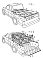
- Fig. 1 is a perspective view of a pickup truck having a truck bed fitted with a cover in accordance with the present invention;
- Fig. 2 is similar to Fig. 1 but showing two of the cover panels in an opened position;
- Fig. 3 is similar to Figs. 1 and 2 but showing an alternative opened position;
- Fig. 4 is a partial view of the cover as taken on view lines 4-4 of Fig. 1;
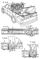
- Fig. 5 is a partial section view of a hinge connection as taken on view lines 5-5 of Fig. 1;
- Fig. 6 is a view similar to Fig. 5 but showing the hinge connection in opened position;
- Fig. 7 is a section view as taken on view lines 7-7 of Fig. 1;
- Fig. 8 is a section view as taken on view lines 8-8 of Fig. 1;
- Fig. 9 is a section view as taken on view lines 9-9 of Fig. 10;
- Fig. 10 is a section view as taken on view lines 10-10 of Fig. 9;
- Fig. 11 is a section view as taken on view lines 11-11 of Fig. 10;
- Fig. 12 is a partial section view as taken on view lines 12-12 of Fig. 4; and
- Fig. 13 is a section view as taken on view lines 13-13 of Fig. 12.
- The drawings show three panels referred to herein as the
front panel 10, thecentre panel 12, and therear panel 14. The threepanels - In plastics, the panel is moulded to include depending support
ribs 16 an dependingside edges 18 surrounding the panel on all four sides. Theribs 16 andside edges 18 provide increased strength to the material, with theedges 18 also providing the means for sealing the cover and for affixing the various hardware add-ons. It also provides the support base for the hinge portions at the front and rear edges which will now be explained. - Reference is made to Figs. 5 and 6 and it will be noted from Fig. 1 that Fig. 5 is a cross-section through the interconnection of
panels Reference number 18r represents the rear edge of thepanel 12 and reference number 18f represents the front edge ofpanel 14. Moulded out ofrear edge 18r ofpanel 12 is a channel-shaped rearwardly extendedhinge portion 20. Moulded out of front edge 18f ofpanel 14 is a channel-shaped forwardly extendedhinge portion 22. - As illustrated in Figs. 5 and 6, the channel shape of
portion 20 has a radius that nests inside the channel shape ofportion 22.Portions panels panel 12 at therear edge 18r is a rigid brace member 24 (a hardware add-on). Bracemember 24, in cooperation withhinge portion 20 defines a curved cavity in which thehinge portion 22 resides with thebrace member 24 supporting thehinge portion 22 ofpanel 14 as illustrated in Figs. 5 and 6. (Note from Fig. 2 however that thebrace member 24 need not extend the full width of the panel. It may be a single piece across the centre portion of the panel or two pieces, one at each side of the panel.) - The hinge portions are interlocked as illustrated in Fig. 5. From Figs. 4 and 12 (and the dash line indication of Fig. 5) it will be noted that
side edge 18s ofpanel 12 overlaps thehinge portion 22 ofpanel 14 when the panels are interlocked and laid flat as shown in solid lines of Fig. 5. However, thepanels hinge portion 22 is pivoted to a point where it clears the end ofside edge 18s (see Fig. 6) and the panel can be slid off of the truck bed as illustrated by thearrows 25 in Fig. 2. - It will be appreciated that when reassembling the panels, the two panels must be oriented as shown in Fig. 6 and slid together in substantially edge-to-edge alignment, before they can be relatively pivoted and both laid flat on the truck bed. The
side edge 26 ofhinge portion 22 is relieved or beveled as illustrated in Fig. 12 so as to cam the two pieces together if slightly misaligned. - Reference is now made to the lock mechanism illustrated in Figs. 2, 3, 9, 10 and 11. As noted generally in Figs. 2 and 3, a
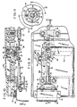
toggle mechanism 28 activates a pair oflocking rods rods brackets 34. The brackets guide the rods into and out of lockinglugs 36 mounted to the truck bed side walls 38 (see Fig. 2). - The
toggle mechanism 28 is specifically illustrated in Figs. 9, 10 and 11. Atoggle lever 40 including flange 41 is fastened bybolt 42 to ashaft 44. Theshaft 44 and flange 41 are locked against relative turning bysplines 57. Ahandle 46 is formed integrally with theshaft 44. Thehandle 46 which is exposed through the top of the panel (Figs 1-3) is movable through a 90 degree turn between a locked position (this position being indicated by 46c in Fig. 9) and an open position (indicated by 46p in Fig. 9). - The
toggle lever 40 is connected at eachend rods short rod 32, when the rods are extended, is projected through abracket 34 and into locking engagement with lockinglug 36 fastened to the pickup bed wall as illustrated in Figs. 9 and 10. The long rod is similarly projected through abracket 34 and a corresponding lockinglug 36 on the opposite pickup bed wall but such is not illustrated. It is desirable to have the lockinglug 36 andend bracket 34 in close proximity and to achieve that, aspacer 54 or spacers (if more than one is required) are provided between the truck bed wall and lug 36 to extend the lug further into the truck bed interior and closer to thebracket 34. The bottom edge ofbracket 34 has abevel 56 as seen in Fig. 10 to guide the bracket to the side of the locking lug as the panel is closed. - It will be observed that the projected
end 58 of the lockingrods slot 60 through the lockinglug 36 is also beveled so that as the rod is inserted, the beveled surfaces engage and force a drawing down of the panel. This action assures a tight fit to prevent rattles. - The open position of the toggle mechanism and locking rods is illustrated in dash lines in Fig. 9. The
toggle lever 40 is rotated 90 degrees (by turning ofhandle 46 to position 46p). This action draws the lockingrods - The turning limitation of the toggle lever is controlled by a projection 43 (Fig. 11) that extends upwardly from flange 41 and into a
slot 45 formed in the panel. Note from Fig. 11 thatprojection 43 can pivot from the position shown to its open position 90 degrees counter clockwise as indicated byarrow 47. Also formed in the panel are V-grooves projection 53 but which may have various configurations) is projected from the flange 41 and engages thegrooves detent 53 engagesgroove 51 in the locked position and will engagegroove 49 in the open position. With the detent in either groove, inadvertent turning of the toggle lever 40 (andshaft 44 and integral handle 46) is resisted. This resistance is determined by compression of O-ring seal 55. - It is to be noted that should a force be applied to the
handle 46 to break the handle and/or its shaft 44 (e.g. in a theft attempt), the interlocking of the toggle lever will be retained in that thebrackets 34 support the rods and they in turn support the toggle lever. As will be subsequently explained, key locking of the locking mechanism occurs by reason of lockinglug 88 engaging and holding the toggle lever in its locked position. Breaking ofhandle 46 thus does not cause disassembly and the key-locked position is maintained. - Reference is now made to Figs. 1 and 8 illustrating the
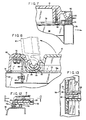
anchor strip 62 and the pivotal connection forpanel 10. Theanchor strip 62 is configured to resemble the rear end of a panel. Thus ahinge portion 20 and abrace member 24 are provided on the anchor strip to cradle thehinge portion 22 ofpanel 10. As noted in Figs. 2 and 3, the panel pivots about the anchor strip similar to the pivoting ofpanel 14 about the rear end ofpanel 12, and is removable in the same way.Anchor strip 62 is securely fastened to the truckbed front wall 64 bybolts 66. As illustrated, the three components of theanchor strip 62; i.e. thebrace member 68, thebrace member 24 andhinge portion 20, are separate pieces bolted together bybolts 70. - Reference is now made to Figs. 3, 10, 7 and 8. Fig. 3 illustrates in general a
weather strip 72 that is adhered to the top edge of theside walls 38. A cross-section of this weather strip is shown in Figs. 10 and 12. Aweather strip 74 is anchored to the top edge of the front wall of the truck (see Fig. 8) and athird weather strip 76 is adhered to the top edge of the tailgate 78 (Fig. 7). - Referring first to Fig. 7, the
panel 14 being similar topanels hinge portion 20. Thehinge portion 20 has no function forpanel 14, however. Thus anovercover 80 is attached over thehinge portion 20 withbolt 82. This overcover has two functions. The first function is to finish off the back end of the cover for cosmetic purposes. The second is to provide an interlock withweather strip 76. - Note the three
flanges 84 that depend fromovercover 80 which fit into a center groove of the strip and at either side. With the weather strip securely adhered to thetailgate 78 and with thepanel 14 closed to cause interlocking of theflanges 84 andweather strip 76, the tailgate cannot be opened. The interlocking also prevents any leakage of water into the truck bed through the interfacing of the tailgate and rear panel. - Reference is now made to Fig. 8 wherein it will be noted that the
weather strip 74 is adhered to the top edge of thefront wall 64 of the truck bed. Water will not leak into the truck bed through the interfacing of theanchor strip 62 at thetruck bed wall 64. - Referring now to Fig. 10, the side wall weather strip 72 (adhered to truck bed side walls 38) is configured with a pair of strip portions 72a and b that form therebetween a drain channel. The upper engaging face of strip portion 72a is slightly canted and because the strip is elastomeric, and because of the camming action of the locking bars (at 58), the cover panels are drawn down onto the strip portion and tightly sealed against water leakage.
- Should any water get through this seal, the drain channel between
portions 72a and 72b will direct the water along the edge of the side wall and discharge it at either end. Theportion 72b has the further function of supporting dependingedge portions 22 that extend over the side edge of the truck bed covers and overportion 72b but which terminates short of the weather strip portion 72a. (See Fig. 12) This edge portion support helps to eliminate rattle of the cover panels. - From the above it will be appreciated that the entire side edge of the cover is sealed against water leakage. There still exists, however, the interfacing as between the adjacent panel edges. With reference to Fig. 5, it will be noted that with the panels drawn down tightly by the locking rods engaging the locking lugs, and due to the channel-shaped configuration of the
hinge portions - The above pickup cover is adapted to fit a variety of truck bed sizes. First the length must be determined. Whereas the three panels are a standard size, the
anchor strip 62 is provided in different lengths to accommodate varying truck bed lengths. - The standard width of the panels will fit a variety of pickup widths. Note from Fig. 10 that the
pickup side wall 38 has a wide top edge relative to theweather strip 72. The same panel width will simply extend over more or less of the top edge to accommodate truck bed width differences by as much as several inches. - The
weather strip 72 is adhered on the top edges of the side walls to match the panel width. Thefront strip 74 is applied to the front wall and theanchor strip 62 is securely fastened to the front wall as illustrated in Fig. 8. Theweather strip 76 is adhered to the top edge of the tailgate. The locking lugs are carefully located on the side walls, usingspacers 54 to ensure a close proximity of thelug 36 and guidebrackets 34 as illustrated Fig. 9. With these lugs fixed properly in place, the modifications to the truck bed are essentially completed. - The three panels as explained are produced from the same mould and the same locking mechanism is applied to each. Nothing more is added to the
front panel 10. Thecentre panel 12 is fitted with abrace member 24 along its rear edge as illustrated in Fig. 5, and an overcover is fitted to the rear edge of therear panel 14 as illustrated in Fig. 7. - The three panels are similar in size, each being about 62.9 by 150 cm. (24-3/4 by 59 inches) for the small size of pickup trucks and about 83 by 170 cm. (32-1/2 by 67 inches) for the large size pickup trucks. The panels are injected moulded high density polyethylene and are tough and somewhat flexible when produced with 5.1 cm. (0.200 inch) thick walls and depending ribs and edge walls of approximately 2.54 cm. (one inch). In either truck size the panels are easy to handle, weighing about 6.4 kg. (14 lbs.) for the small panels and 9.1 kg. (20 lbs.) for the larger panels. The pickup as modified can be readily used in a conventional manner, with some care that the weather strips and anchor strip is not roughly abused. However, it is contemplated that tough weather stripping materials will be used and strong adhesive to adhere them to the truck bed walls.
- When security against rain or theft is a concern, the three panels are removed from storage and fitted to the truck box. The front panel is stood up in the position of Fig. 3 but positioned to one side thereof. The
hinge portion 22 is aligned between thehinge portion 20 andbrace member 24 of the anchor strip, as illustrated in dash lines of Fig. 8, and the panel is simply slid into place. One or the other of the center or rear panels are simply laid in the proper position and the locking mechanism engaged to lock that panel to the truck bed. The last panel is then slid into interlocking engagement with the hinge portion of the positioned panel, in a manner similar to that of the front panel. Both the front panel and this latter panel are then folded down onto the truck bed with thehinge portion 20 of thefront panel 10 nesting in thehinge portion 22 ofpanel 12. The lock mechanism for each is then engaged by the turning ofhandles 46. - A key-
lock mechanism 86 securely locks the panels to the truck bed (see Figs. 1-3, and 9). The key-lock 86 is key operated to pivot thelug 88. It is in a locked position wherelug 88 abuts theend 50 oflever 40 of thelock mechanism 46 to thereby prevent turning oftoggle lever 40 and withdrawal of the rods from locking lugs 36 (solid line position of Fig. 9). It is in an unlocked position wherelug 88 is pivoted out of engagement with thelever 40 to permit withdrawal of the rods by turning ofhandle 46. In the locked and key-locked positions, the interior of the truck bed is secure (noting, of course, that the tailgate was closed prior to placement of the cover panels). - When loading and unloading of the bed is desired, any one of several panel openings are possible. The
rear panel 14 can be unlocked and opened independent of either of the other panels as can thefront panel 10. Thecenter panel 12 can be unlocked and opened whenrear panel 12 is closed, but only after the front panel has been opened sufficiently to pivot thehinge portion 22 out from under thehinge portion 20 of the front panel. And of course, the multiple panel openings shown in Figs. 2 and 3 are achievable as well. - Opening of a panel is accomplished in a one-handed operation. The fingers of one hand grip the handle and turn it 90 degrees to the
position 46p and, using the handle as a lifting lever, the panel is simply raised or pivoted about its hinge connection to the stop generated by the interference between panels at position 92 (Figs 4 and 6). The panel is held in the open position due to the panel having crossed the vertical position where gravity action maintains the open position. - Whereas the panels and the interlocking of the panels is designed to withstand substantial abuse, it is recognized that an excessive force can be inadvertently applied when opening a panel. Opening the panels in a high wind, or driving off with a panel opened, are two situations when such excessive force may occur. The present panels are designed to provide a break-away hinge in such extreme conditions. Note from Fig. 6 that in the extreme opened position, a continued forcing of the open panel in the direction of arrow 90 will generate a leveraged force about the "stop"
point 92. The force urges opening of thecurved end 94 ofbrace member 24. By providing some springiness to the brace member, the panel will simply break away from its interlocked position. Providing some springiness to this brace member can be accomplished in a number of ways. Preferably the material selected for thebrace member 24 is a suitable metal that has limited resilience when subjected to a substantial force and thus opens sufficiently to release thepanel 14 under such conditions as described. A suitable material for thebrace member 24 is e.g. 0.16 cm. (1/16 inch) thick 12 gauge mild steel. - Numerous variations of the specific embodiment disclosed can be made without departing from the scope of the invention which is defined by the claims appended hereto.
Claims (17)
Applications Claiming Priority (2)
| Application Number | Priority Date | Filing Date | Title |
|---|---|---|---|
| US07/085,397 US4824162A (en) | 1987-08-13 | 1987-08-13 | Cover for pickup truck bed |
| US85397 | 2008-07-31 |
Publications (2)
| Publication Number | Publication Date |
|---|---|
| EP0303386A2 true EP0303386A2 (en) | 1989-02-15 |
| EP0303386A3 EP0303386A3 (en) | 1989-12-27 |
Family
ID=22191346
Family Applications (1)
| Application Number | Title | Priority Date | Filing Date |
|---|---|---|---|
| EP88307139A Withdrawn EP0303386A3 (en) | 1987-08-13 | 1988-08-02 | Cover for pickup truck bed |
Country Status (6)
| Country | Link |
|---|---|
| US (1) | US4824162A (en) |
| EP (1) | EP0303386A3 (en) |
| JP (1) | JPS6456281A (en) |
| AU (1) | AU593962B2 (en) |
| BR (1) | BR8800108A (en) |
| CA (1) | CA1296596C (en) |
Cited By (3)
| Publication number | Priority date | Publication date | Assignee | Title |
|---|---|---|---|---|
| US5102185A (en) * | 1987-05-22 | 1992-04-07 | Trail-R-Van Inc. | Load bed lift-roof cover |
| WO2002014096A2 (en) * | 2000-08-17 | 2002-02-21 | Decoma Exterior Trim Inc. | Multi-panel tonneau cover |
| CN104040101A (en) * | 2012-01-12 | 2014-09-10 | 马特尔公司 | Pinch-relief hinged assemblies and children' products including pinch-relief hinged assemblies |
Families Citing this family (53)
| Publication number | Priority date | Publication date | Assignee | Title |
|---|---|---|---|---|
| FR2642656B1 (en) * | 1989-02-09 | 1991-11-15 | Salomon Sa | SKI SAFETY FASTENER FOR HOLDING THE FRONT OF A SHOE MOUNTED ON THE SKI |
| US5201561A (en) * | 1991-02-15 | 1993-04-13 | Brown Michael F | Storage unit for use in pickup trucks |
| US5263761A (en) * | 1992-01-21 | 1993-11-23 | Cr&I Inc. | Vehicle modular rail system |
| US5584521A (en) * | 1992-01-21 | 1996-12-17 | Cr&I Inc. | Vehicle modular rail system |
| US5595417A (en) * | 1995-07-26 | 1997-01-21 | Thoman; David C. | Tonneau cover for a pick-up truck |
| US5653491A (en) * | 1995-09-15 | 1997-08-05 | Steffens Enterprises, Inc. | Folding cargo bay cover for pickup trucks |
| US5961173A (en) * | 1997-02-26 | 1999-10-05 | Repetti; Thomas A. | Work box frame |
| US5931521A (en) * | 1997-05-29 | 1999-08-03 | Kooiker; John | Folding cover for pickup truck bed |
| US6547310B2 (en) | 1997-10-31 | 2003-04-15 | Eugene A. Myers | Truck bed cover |
| US6352296B1 (en) | 1998-04-28 | 2002-03-05 | Advance Cover Company | Folding cover for pickup truck bed |
| US6082806A (en) * | 1998-10-16 | 2000-07-04 | Bogard; Donald E. | Pick-up truck tonneau cover |
| US6217102B1 (en) * | 1998-10-26 | 2001-04-17 | Michael W. Lathers | Apparatus for covering a truck box (tonneau cover) and mounting structure therefor |
| US6325439B1 (en) | 1999-06-18 | 2001-12-04 | Steffens Enterprises, Inc. | Hanging storage unit for a truck cargo bay |
| US6227602B1 (en) * | 1999-08-23 | 2001-05-08 | Donald E. Bogard | Pick-up truck lightweight cargo cover |
| US6338520B2 (en) | 1999-09-02 | 2002-01-15 | The Budd Company | Tonneau cover and attachment assembly |
| US6183035B1 (en) | 1999-09-02 | 2001-02-06 | The Budd Company | Tonneau cover and attachment assembly |
| US6299232B1 (en) | 1999-11-01 | 2001-10-09 | Edgar Davis | Removeable vehicle bed cover |
| AU2001227963A1 (en) | 2000-01-20 | 2001-07-31 | The Budd Company | Tonneau cover stake pocket attachment system and tailgate interlock |
| US6422635B1 (en) * | 2000-01-20 | 2002-07-23 | Steffens Enterprises, Inc. | Folding cargo bay cover for pickup truck |
| US6588826B1 (en) * | 2000-02-29 | 2003-07-08 | Scott Arthur William Muirhead | Rigid cover assembly for a pickup truck |
| US6234559B1 (en) | 2000-06-05 | 2001-05-22 | Vista Consolidated, Inc. | Rigid tonneau cover with integral storage box |
| US6447045B1 (en) | 2000-07-17 | 2002-09-10 | Algonquin International Industries, Inc. | Tonneau cover mounting system |
| CA2354577C (en) * | 2001-06-19 | 2007-10-09 | U-Haul International, Inc. | Trailer |
| US6572174B2 (en) * | 2001-09-24 | 2003-06-03 | Javier Hernandez | Vehicle structure |
| DE10237962A1 (en) * | 2002-08-20 | 2004-03-04 | Dr.Ing.H.C. F. Porsche Ag | Structure for a motor vehicle |
| US6883855B2 (en) * | 2003-04-01 | 2005-04-26 | Diamondback Automotive Accessories, Inc. | Hinged tonneau cover for transporting a significant top load |
| US7066523B2 (en) | 2003-06-11 | 2006-06-27 | Asc Incorporated | Tonneau cover for automotive vehicle |
| US7555816B2 (en) * | 2003-10-06 | 2009-07-07 | Walker Eric L | Toolbox latch and hinge apparatus and method |
| US7052071B2 (en) * | 2004-05-27 | 2006-05-30 | Steffens Enterprises, Inc. | Cover and latch for vehicle cargo bed with tailgate |
| US7320494B1 (en) * | 2004-06-03 | 2008-01-22 | Jerry Wilson | Hardware to facilitate storing pickup bed cover |
| US7086685B1 (en) | 2005-03-28 | 2006-08-08 | Zeugner Scott J | Pickup truck bed cover |
| US7318618B1 (en) * | 2006-06-09 | 2008-01-15 | Cyc Engineering | Reinforced tonneau cover |
| DE102006053197B3 (en) * | 2006-11-09 | 2008-02-07 | Automotive Group Ise Industries Hainichen Gmbh | Hinge for attaching e.g. door, at motor vehicle body, has door console and column console with contact surfaces formed by main and auxiliary partial surfaces and connecting area, where surfaces and area are differentiated from each other |
| JP4378731B2 (en) * | 2007-09-20 | 2009-12-09 | いすゞ自動車株式会社 | Vehicle bed structure |
| US7753435B2 (en) * | 2007-11-26 | 2010-07-13 | Chrysler Group Llc | Water shield for vehicle door |
| US20100127529A1 (en) * | 2008-11-21 | 2010-05-27 | Adrian Nicholas Alexander Elliott | Vehicle storage cover assembly |
| US8544934B2 (en) * | 2011-10-31 | 2013-10-01 | Israel Maimin | Roll up pick-up truck box cover with lock down slats |
| US9027685B2 (en) * | 2013-03-14 | 2015-05-12 | Mattel, Inc. | Latch assemblies and children's products that include latch assemblies |
| US9352641B2 (en) * | 2014-01-14 | 2016-05-31 | Cargo Solutions Group, LLC | Integrated pickup truck cargo management system |
| US9555735B2 (en) * | 2015-01-08 | 2017-01-31 | Toyota Motor Engineering & Manufacturing North America, Inc. | Molded tonneau cover apparatus |
| US9925853B2 (en) | 2015-03-30 | 2018-03-27 | Jennifer Aubrey | Load bearing tonneau structure |
| US10328778B2 (en) | 2015-03-30 | 2019-06-25 | Advanced Metal Products, Inc. | Load bearing tonneau cover with integral track, improved latch to vehicle and custom frame attachment |
| US10940743B2 (en) | 2015-03-30 | 2021-03-09 | Advanced Metal Products, Inc. | Load bearing tonneau cover with integral track, improved latch to vehicle and custom frame attachment |
| US10053343B1 (en) | 2017-02-07 | 2018-08-21 | Rodney Cameron | Truck bed scissor lift |
| USD829634S1 (en) | 2017-02-24 | 2018-10-02 | Cargo Solutions Group, LLC | Truck bed cargo system |
| US20180312099A1 (en) * | 2017-04-26 | 2018-11-01 | Ford Global Technologies, Llc | Hybrid tonneau cover/work surface for vehicle |
| US10960935B2 (en) * | 2019-01-30 | 2021-03-30 | Toyota Motor Engineering & Manufacturing North America, Inc. | Truck bed covers including a compartment forming panel |
| US11084411B2 (en) * | 2019-04-18 | 2021-08-10 | Jim Flanagan | Modular cargo slider |
| US11331990B2 (en) | 2019-05-21 | 2022-05-17 | Extang Corporation | Multi-hinge tonneau cover |
| JP7232717B2 (en) | 2019-06-10 | 2023-03-03 | 西川ゴム工業株式会社 | Seal structure of truck bed with shutter |
| AU2020315365A1 (en) | 2019-07-17 | 2022-02-24 | Leer Group | Multi-panel tonneau cover |
| US11267323B2 (en) | 2020-04-20 | 2022-03-08 | Tectum Holdings, Inc. | Tonneau cover with torsion element |
| JP7426970B2 (en) * | 2021-07-21 | 2024-02-02 | 株式会社竹内製作所 | Vehicle cover opening/closing mechanism |
Citations (6)
| Publication number | Priority date | Publication date | Assignee | Title |
|---|---|---|---|---|
| US3578378A (en) * | 1969-04-11 | 1971-05-11 | Edwin G Anderson | Telescopic and pivotal cover assembly for open bed vehicles |
| US4277098A (en) * | 1978-09-18 | 1981-07-07 | Lloyd Gibney | Foldable truck cap assembly |
| US4313636A (en) * | 1979-01-15 | 1982-02-02 | Deeds Larry B | Folding cover for truck bed |
| US4418954A (en) * | 1980-07-28 | 1983-12-06 | Buckley John A | Foldable cover for a truck bed |
| US4550945A (en) * | 1982-07-26 | 1985-11-05 | Pei, Inc. | Truck bed closure |
| US4615557A (en) * | 1985-02-27 | 1986-10-07 | Arnie Robinson | Security cover for truck beds |
Family Cites Families (2)
| Publication number | Priority date | Publication date | Assignee | Title |
|---|---|---|---|---|
| DE2230723A1 (en) * | 1971-08-03 | 1973-02-15 | Waldner Fa Felix | TILT DOOR OR THE SAME |
| US4221423A (en) * | 1978-11-01 | 1980-09-09 | Stone Raymond J | Cover for a vehicle box |
-
1987
- 1987-08-13 US US07/085,397 patent/US4824162A/en not_active Expired - Lifetime
- 1987-12-08 AU AU82228/87A patent/AU593962B2/en not_active Ceased
-
1988
- 1988-01-13 BR BR8800108A patent/BR8800108A/en unknown
- 1988-01-18 JP JP63008195A patent/JPS6456281A/en active Pending
- 1988-06-01 CA CA000568305A patent/CA1296596C/en not_active Expired - Lifetime
- 1988-08-02 EP EP88307139A patent/EP0303386A3/en not_active Withdrawn
Patent Citations (6)
| Publication number | Priority date | Publication date | Assignee | Title |
|---|---|---|---|---|
| US3578378A (en) * | 1969-04-11 | 1971-05-11 | Edwin G Anderson | Telescopic and pivotal cover assembly for open bed vehicles |
| US4277098A (en) * | 1978-09-18 | 1981-07-07 | Lloyd Gibney | Foldable truck cap assembly |
| US4313636A (en) * | 1979-01-15 | 1982-02-02 | Deeds Larry B | Folding cover for truck bed |
| US4418954A (en) * | 1980-07-28 | 1983-12-06 | Buckley John A | Foldable cover for a truck bed |
| US4550945A (en) * | 1982-07-26 | 1985-11-05 | Pei, Inc. | Truck bed closure |
| US4615557A (en) * | 1985-02-27 | 1986-10-07 | Arnie Robinson | Security cover for truck beds |
Cited By (5)
| Publication number | Priority date | Publication date | Assignee | Title |
|---|---|---|---|---|
| US5102185A (en) * | 1987-05-22 | 1992-04-07 | Trail-R-Van Inc. | Load bed lift-roof cover |
| WO2002014096A2 (en) * | 2000-08-17 | 2002-02-21 | Decoma Exterior Trim Inc. | Multi-panel tonneau cover |
| WO2002014096A3 (en) * | 2000-08-17 | 2002-06-20 | Decoma Exterior Trim Inc | Multi-panel tonneau cover |
| US6702359B2 (en) | 2000-08-17 | 2004-03-09 | Decoma Exterior Trim Inc. | Multi-panel tonneau cover |
| CN104040101A (en) * | 2012-01-12 | 2014-09-10 | 马特尔公司 | Pinch-relief hinged assemblies and children' products including pinch-relief hinged assemblies |
Also Published As
| Publication number | Publication date |
|---|---|
| EP0303386A3 (en) | 1989-12-27 |
| BR8800108A (en) | 1989-02-28 |
| AU8222887A (en) | 1989-02-16 |
| CA1296596C (en) | 1992-03-03 |
| US4824162A (en) | 1989-04-25 |
| AU593962B2 (en) | 1990-02-22 |
| JPS6456281A (en) | 1989-03-03 |
Similar Documents
| Publication | Publication Date | Title |
|---|---|---|
| EP0303386A2 (en) | Cover for pickup truck bed | |
| CA3014552C (en) | Tool box | |
| EP0513853B1 (en) | Luggage case | |
| US6557918B2 (en) | Vehicle cargo area extender having sliding lid | |
| US3069199A (en) | Cover for the beds of pick-up trucks | |
| US6478355B1 (en) | Adaptable pick up truck configuration | |
| US4828312A (en) | Collapsible security storage apparatus for truck beds | |
| US4531775A (en) | Load bearing security cover for pick up truck | |
| US4799726A (en) | Removable canopy cover | |
| US5087093A (en) | Hinged cover for pick-up trucks | |
| US6561560B2 (en) | Vehicle cargo area extender | |
| US6059341A (en) | Quarter side storage compartment | |
| US4260084A (en) | Vehicle luggage racks and containers carried thereby | |
| EP0983901B1 (en) | Vehicle Storage System | |
| CA2118161A1 (en) | Refuse Container for Segregation Refuse and Truck Attachment for Use in Connection Therewith | |
| CA2228540A1 (en) | Cam-operated hatch cover lock | |
| CA2098209A1 (en) | Hatch cover lock and hinge | |
| US3712091A (en) | Method and device for handling motor vehicle keys | |
| GB2144627A (en) | Trays | |
| US5979963A (en) | Security cover for pick-up truck beds | |
| US4428155A (en) | Releasable hinge device for removable panels | |
| US6581999B1 (en) | Receptacle extension apparatus and method | |
| US3704606A (en) | Filler tube locking device | |
| USD356415S (en) | Lockable cradle for hand truck | |
| US20040262320A1 (en) | Waste container with security frame |
Legal Events
| Date | Code | Title | Description |
|---|---|---|---|
| PUAI | Public reference made under article 153(3) epc to a published international application that has entered the european phase |
Free format text: ORIGINAL CODE: 0009012 |
|
| AK | Designated contracting states |
Kind code of ref document: A2 Designated state(s): DE FR GB |
|
| PUAL | Search report despatched |
Free format text: ORIGINAL CODE: 0009013 |
|
| AK | Designated contracting states |
Kind code of ref document: A3 Designated state(s): DE FR GB |
|
| RHK1 | Main classification (correction) |
Ipc: B60P 7/02 |
|
| 17P | Request for examination filed |
Effective date: 19900614 |
|
| 17Q | First examination report despatched |
Effective date: 19901203 |
|
| STAA | Information on the status of an ep patent application or granted ep patent |
Free format text: STATUS: THE APPLICATION HAS BEEN WITHDRAWN |
|
| 18W | Application withdrawn |
Withdrawal date: 19911123 |
|
| R18W | Application withdrawn (corrected) |
Effective date: 19911123 |