EP0303170B1 - Control system for a variable speed hydro-power plant apparatus - Google Patents
Control system for a variable speed hydro-power plant apparatus Download PDFInfo
- Publication number
- EP0303170B1 EP0303170B1 EP88112625A EP88112625A EP0303170B1 EP 0303170 B1 EP0303170 B1 EP 0303170B1 EP 88112625 A EP88112625 A EP 88112625A EP 88112625 A EP88112625 A EP 88112625A EP 0303170 B1 EP0303170 B1 EP 0303170B1
- Authority
- EP
- European Patent Office
- Prior art keywords
- turbine
- rotating speed
- generator
- output
- speed
- Prior art date
- Legal status (The legal status is an assumption and is not a legal conclusion. Google has not performed a legal analysis and makes no representation as to the accuracy of the status listed.)
- Expired - Lifetime
Links
- 238000012937 correction Methods 0.000 claims description 39
- XLYOFNOQVPJJNP-UHFFFAOYSA-N water Substances O XLYOFNOQVPJJNP-UHFFFAOYSA-N 0.000 claims description 26
- 230000007423 decrease Effects 0.000 claims description 25
- 238000000034 method Methods 0.000 claims description 20
- 230000008859 change Effects 0.000 claims description 12
- 238000013459 approach Methods 0.000 claims description 10
- 238000011144 upstream manufacturing Methods 0.000 claims description 9
- 230000001965 increasing effect Effects 0.000 claims description 8
- 230000003247 decreasing effect Effects 0.000 claims description 7
- 238000001514 detection method Methods 0.000 claims description 3
- 238000012986 modification Methods 0.000 claims description 2
- 230000004048 modification Effects 0.000 claims description 2
- 238000012544 monitoring process Methods 0.000 claims 1
- 230000006698 induction Effects 0.000 description 18
- 238000010586 diagram Methods 0.000 description 13
- 230000005284 excitation Effects 0.000 description 11
- 238000004804 winding Methods 0.000 description 8
- 230000000694 effects Effects 0.000 description 7
- 230000004044 response Effects 0.000 description 6
- 230000001052 transient effect Effects 0.000 description 3
- 230000009471 action Effects 0.000 description 2
- 238000013461 design Methods 0.000 description 2
- 230000000644 propagated effect Effects 0.000 description 2
- 238000005086 pumping Methods 0.000 description 2
- 230000002159 abnormal effect Effects 0.000 description 1
- 230000001133 acceleration Effects 0.000 description 1
- 230000002411 adverse Effects 0.000 description 1
- 230000004075 alteration Effects 0.000 description 1
- 238000010420 art technique Methods 0.000 description 1
- 239000002131 composite material Substances 0.000 description 1
- 239000000470 constituent Substances 0.000 description 1
- 230000001419 dependent effect Effects 0.000 description 1
- 238000011161 development Methods 0.000 description 1
- 230000018109 developmental process Effects 0.000 description 1
- 230000002708 enhancing effect Effects 0.000 description 1
- 230000001747 exhibiting effect Effects 0.000 description 1
- 238000000605 extraction Methods 0.000 description 1
- 230000014509 gene expression Effects 0.000 description 1
- 230000008569 process Effects 0.000 description 1
- 230000009467 reduction Effects 0.000 description 1
- 230000006641 stabilisation Effects 0.000 description 1
- 238000011105 stabilization Methods 0.000 description 1
- 230000001360 synchronised effect Effects 0.000 description 1
Images



Classifications
-
- F—MECHANICAL ENGINEERING; LIGHTING; HEATING; WEAPONS; BLASTING
- F03—MACHINES OR ENGINES FOR LIQUIDS; WIND, SPRING, OR WEIGHT MOTORS; PRODUCING MECHANICAL POWER OR A REACTIVE PROPULSIVE THRUST, NOT OTHERWISE PROVIDED FOR
- F03B—MACHINES OR ENGINES FOR LIQUIDS
- F03B15/00—Controlling
- F03B15/02—Controlling by varying liquid flow
- F03B15/04—Controlling by varying liquid flow of turbines
- F03B15/06—Regulating, i.e. acting automatically
-
- Y—GENERAL TAGGING OF NEW TECHNOLOGICAL DEVELOPMENTS; GENERAL TAGGING OF CROSS-SECTIONAL TECHNOLOGIES SPANNING OVER SEVERAL SECTIONS OF THE IPC; TECHNICAL SUBJECTS COVERED BY FORMER USPC CROSS-REFERENCE ART COLLECTIONS [XRACs] AND DIGESTS
- Y02—TECHNOLOGIES OR APPLICATIONS FOR MITIGATION OR ADAPTATION AGAINST CLIMATE CHANGE
- Y02E—REDUCTION OF GREENHOUSE GAS [GHG] EMISSIONS, RELATED TO ENERGY GENERATION, TRANSMISSION OR DISTRIBUTION
- Y02E10/00—Energy generation through renewable energy sources
- Y02E10/20—Hydro energy
Definitions
- the present invention relates to a control system for a variable speed hydro-power plant according to the preamble portion of claim 1.
- the present invention further shows a control system for a variable speed hydro-power plant apparatus realizing a control method well suited to a variable speed pumping-up power plant apparatus which shared an upstream or downstream side pipe line with another hydraulic machinery and which comprises a pump turbine exhibiting an S-shaped characteristics in a turbine or a water turbine operation region.
- a variable speed hydro-power plant apparatus to which the present invention is applied uses a wound-rotor induction generator as an induction machine which is driven by a pump turbine or a water turbine (herein-below, simply termed "pump turbine”), and it excites the secondary winding thereof A.C.-wise through a frequency converter.
- pump turbine a pump turbine or a water turbine
- variable speed hydro-power plant apparatus is therefore noticed owing to the feature that any desired rotating speed of the pump turbine can be established in the state in which the output frequency of the generator is held at an A.C. power line system frequency, so the variable speed hydro-power plant apparatus can be operated at a rotating speed affording a high pump turbine efficiency, or that when the generator is subjected to a variable speed pumping-up operation as a motor, an AFC (automatic frequency control) responsive operation is possible in spite of the operation as a simple constant speed motor.
- AFC automatic frequency control
- Japanese Patent Application Laid-open No. 72998/1984 has proposed one technique for avoiding the entry of an operation into the unstable turbine operation region of the S-shaped characteristics at the stage of shift from no load to a rated load in the variable speed hydro-power plant apparatus.
- the guide vane opening degree control of the pump turbine is preferred to a rotating speed control based on the induction generator.
- the output of the induction generator is controlled according to a generator output command which is given to the generator, while the opening degree of the guide vane is first led to an opening degree corresponding to the changed generator output command as quickly as possible, and the appropriate rotating speed control is thereafter performed slowly.
- the technique has the effect that the operation can be hindered from entering the unstable turbine operation region of the S-shaped characteristics at the start of the pump turbine.
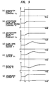
- the generator output command P0 is now raised step-wise as shown at the section (a) in Fig. 9, at a point of time t0 with the intention of raising the generator output P as shown at the section (g) in Fig. 9. Then, the generator output P of the induction generator rises following up the change of the generator output command P0 as shown at the section (a) in Fig. 9.
- the turbine output P T becomes greater than the generator output P, and the rotating speed N begins to rise as shown at the section (f) in Fig. 9.
- the rotating speed deviation ⁇ N thereof from the appropriate rotating speed command N a decreases, and with the decrease of the guide vane opening degree deviation ⁇ Y, the turbine output P T decreases, and the acceleration of the rotating speed N decreases.
- the rotating speed deviation ⁇ N in a steady state is rendered zero by the integral element in the rotating speed control unit.
- the guide vane opening degree deviation ⁇ Y between the appropriate guide vane opening degree command Y a from the turbine characteristics function generation unit and the guide vane opening degree Y corresponds to the error between a characteristics of the pump turbine, and it can be rendered almost zero by enhancing the precision of the function of the turbine characteristics.
- the secondary excitation unit has an integral element etc. built therein for the purpose of adjusting the generator output P to the generator output command P0.
- P P 0
- N N a
- the gain (K1) of the proportional element having a braking effect is made greater, and the gain (K2) of the integral element is made relatively smaller, thereby to raise the response rate of the opening degree of the guide vane to the utmost.
- the turbine output P T and the rotating speed N are set without vibrations as seen from at the sections (a) and (f) in Fig. 9.
- the runner and other devices of the pump turbine are so designed as to demonstrate a sufficient centrifugal pumping action to the end of attaining a high water head during a pumping operation.
- the characteristics of the pump turbine adopted for this design is indicated by a characteristics curve which expresses the relationship between a rotating speed per unit head (N1) and a flow rate per unit head (Q1) under the predetermined opening degree of the guide vane
- the characteristics curve has in the operation region of the pump turbine, the first part in which the value of the flow rate per unit head (Q1) decreases with increase in the value of the rotating speed per unit head (N1) and the second part in which the value of the flow rate per unit head (Q1) decreases with decrease in the value of the rotating speed per unit head (N1).
- S-shaped characteristics part in this specification.
- S-shaped characteristics the characteristics of the pump turbine in the S-shaped characteristics part.
- the operation of the pump turbine is performed in the first part.
- the rotating speed per unit head (N1) increases suddenly and greatly due to an abrupt load decrease or the like, there is the possibility that the pump turbine will rush into the S-shaped characteristics part or region. Once the pump turbine has rushed into the S-shaped characteristics part or region, it becomes, in effect, impossible to continue the operation of the variable speed hydro-power plant apparatus.
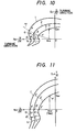
- Fig. 10 The characteristics of the pump turbine having the S-shaped characteristics in the turbine operation region are illustrated in Fig. 10 and Fig. 11.
- Fig. 10 the characteristics of the pump turbine is shown as the relationship between the rotating speed per unit head (N1) and the flow rate per unit head (Q1) with the guide vane opening degree (Y) taken as a parameter.
- symbols N, Q, H and T denote the rotating speed, the flow rate, the effective head and the torque of the pump turbine, respectively.
- Characteristics curves 1 and 1′ are obtained under a comparatively great guide vane opening degree as predetermined. Characteristics curves 2 and 2′ are obtained under a smaller guide vane opening degree. Characteristics curves 3 and 3′ are obtained under a still smaller guide vane opening degree.
- a curve part b-e-i is the S-shaped characteristics part of the characteristics curve 2
- a curve part c-f-j is that of the characteristics curve 3.
- curve parts a′-d′-h′, b′-e′-i′ and c′-f′-j′ are the S-shaped characteristics parts of the characteristics curves 1′, 2′ and 3′, respectively.
- Fig. 11 has close relations with Fig. 10.
- points a , b , c , d , e , f , h , i , and j in Fig. 10 correspond to a′, b′, c′, d′, e′, f′, h′, i′ and j′ in Fig 11, respectively.
- a curve nr is a no-load flow rate curve.
- variable speed hydro-power plant apparatus is operated under conditions differing every moment, and it is sufficiently presumed that the operation approaches or enters the unstable turbine operation region during an ordinary operation except the start operation. Nevertheless, the above stated prior art is not effective as a measure of avoidance and extrication in this case.
- control rate of the guide vane opening degree is inevitably limited when abnormal water hammering should arise in a waterway upstream or downstream of the pump turbine, and it can never be raised up to the response rate level of the generator output control.
- Japanese Patent Laid-Open No. 164080/1986 proposes a method in which, when a variable speed hydro-power plant apparatus is to be put on an electric power system, the rotating speed is set at the minimum value allowable under the effective head (H) on that occasion, whereby the induction generator is stably put on the electric power system without the influence of the S-shaped characteristics turbine operation region.
- US-A-4 382 745 shows a method of controlling the opening and closing of wicked gates of a pump turbine, if the same drops into the S-shaped area of the turbine performance. If this is the case, the wicked gates are controlled to open when it is detected that discharge per unit head decreases with the reduction of speed per unit head. When it is once detected that the ratio of variation in the discharge per unit head to the variation in the speed per unit head is reversed from a positive value to a negative value, the wicked gates are closed. With only the opening of the wicked gates as input to the process of the turbine control system, the reaction is too slow to safely avoid a dropping into the S-shaped area, e.g. if a sudden drop or a sudden rise of the waterline pressure occurs.
- the object of the present invention is to provide a control system for a variable speed hydro-power plant wherein the continuation of a stable and reliable turbine operation can be guaranteed.
- the present invention shall realize a control system for a variable speed hydro-power plant apparatus wherein, when the turbine operation approaches the unstable turbine operation region, such an unstable turbine operation region can be brought back to a stable turbine operation region, and a drop into the S-shaped characteristics turbine operation region can be avoided, in spite of the interference of the water hammering from another hydraulic machinery sharing a pipe.
- a current turbine operating point is grasped on the turbine characteristics diagram of the pump turbine, and when it has approached the unstable turbine operation region, the rotating speed of the pump turbine is forcibly lowered.
- a frequency converter is controlled so as to increase the output of the generator, or the opening degree of the guide vane is controlled so as to decrease the output of the pump turbine, thereby to lower the rotating speed of the pump turbine.
- a variable speed hydro-power plant apparatus comprises a generator connected to an electric power system which is provided with a frequency converter in order to generate power of the same terminal frequency as that of the electric power system independently of its rotor driving speed, and a pump turbine which is directly coupled to a shaft of the generator rotor and which includes variable guide vanes.
- a variable speed hydro-power plant apparatus comprises a generator whose primary winding is connected to an electric power system and whose secondary winding is connected to the electric power system through a secondary excitation control unit, and a pump turbine which is directly coupled to a shaft of the generator rotor and which includes variable guide vanes.
- the present invention Upon detecting an approach of a turbine operating point of the variable speed hydro-power plant apparatus to an unstable turbine operation region, the present invention attains by one of the following control methods, namely, (1) a rotating speed of the pump turbine is lowered, (2) a mechanical output of the pump turbine is made smaller than an output of the generator, (3) only the generator output is increased through the generator output controller so as to make a mechanical output of the turbine smaller than the generator output, and (4) only a mechanical output of the turbine is decreased through the turbine controller so as to make the mechanical output of the turbine smaller than the generator output.
- a rotating speed per unit head and a reference rotating speed per unit head representing allowable maximum speed which is a function of opening degree of the variable guide vane are compared, whereupon a rotating speed of the pump turbine is lowered.
- a stable operation side is a region in which the rotating speed of the pump turbine is not excessively high, and a return to the stable turbine operation side is permitted by lowering the rotating speed of the pump turbine in the variable speed hydro-power plant apparatus in which the rotating speed can be selected separately from and independently of a system frequency.
- the pump turbine Since the pump turbine is accelerated or decelerated on the basis of the difference between mechanical output of the turbine and the generator output, it is effective to increase the generator output or decrease mechanical output of the turbine when a rotating speed of the pump turbine is to be lowered back and kept away from the unstable region.
- the effect of the present invention resides in that, in an ordinary variable speed hydro-power plant mode in which a generator is put on an electric power system, the possibility of the inrush of a pump turbine or a water turbine into a S-shaped characteristics turbine operation region is perfectly eliminated, so the continuation of a stable and reliable turbine operation can be guaranteed.
- the variable speed hydro-power plant apparatus in a turbine mode operation of a variable speed hydro-power plant sharing an upstream or downstream side pipe line with another hydraulic machinery, the variable speed hydro-power plant apparatus comprises a pump turbine which exhibits a S-shaped characteristics in a turbine operation region and includes variable guide vanes, and a generator with a frequency converter, which is so constructed as to generate electric power thereof equal in frequency to that of an electric power system in spite of the fact that a rotating speed of the pump turbine is changed in conformity with an operating state.
- the rotating speed of the variable speed hydro-power plant apparatus is temporarily corrected and controlled, and the temporary rotating speed correction control is released after water hammering in the shared pipe line caused by the abrupt change of the operating state of the other side hydraulic machinery has settled down.
- the rotating speed correction control of lowering the rotating speed of the variable speed hydro-power plant apparatus is performed before-hand, or the rotating speed correction control is validated in a limited specified operation region in accordance with a water head or a rotating speed of the pump turbine or an opening degree of the guide vane on each occasion.
- the rotating speed correction control of lowering the rotating speed of the variable speed hydro-power plant apparatus is simultaneously performed, or the rotating speed correction control is validated in a limited specified operation region in accordance with a water head or a rotating speed of the pump turbine or an opening degree of the guide vane on each occasion.
- Influence ascribable to the change of the operating state of the other side hydraulic machinery sharing the pipe line namely, the lowering of the effective head of the particular variable speed pumping-up plant apparatus ascribable to the water hammering is calculatedly obtained before-hand, and the rotating speed of the hydraulic machinery of the particular variable speed pump turbine plant apparatus is lowered and corrected to the extent that the raise of the rotating speed per unit head attendant upon the lowering of the effective head is cancelled.
- the rotating speed lowering correction may be made previously to a command for changing the operating state of the other side hydraulic machinery, or it may well be made simultaneously at that time.
- the effect of the present invention consists in providing a proper and simple control method which reliably avoids a drop into a S-shaped characteristics turbine operation region threatening the continuous operation of a generator mode operation, in spite of the interference of water hammering phenomenon from another side hydraulic machinery sharing a pipe line.
- FIG. 1 A variable speed hydro-power plant apparatus according to various embodiments of the present invention will be described with reference to the drawings.
- a first embodiment shown in Fig. 1 consists in that a stable turbine operation side is restored by increasing the output of a generator when such need arises.
- the variable speed hydro-power plant apparatus and control devices therefor will be explained.
- numeral 1 designates an induction machine or induction generator which is driven and rotated by a pump turbine 2 directly coupled to the rotor thereof and in a turbine mode.
- the induction generator 1 is subjected to a variable speed operation in such a manner that a secondary winding 1b of the induction generator 1 is supplied with an alternating exciting current which is adjusted to a predetermined frequency in accordance with the rotating speed of the induction generator 1 by means of a secondary excitation control unit 3 including a frequency converter, while A.C. power at a frequency equal to the frequency of an A.C. power line system 4 is delivered from a primary winding 1a of the induction generator 1.
- Numeral 12 indicates an exciting transformer.
- variable speed hydro-power plant apparatus is schematically constructed as stated above.
- One of the control terminals of the variable speed hydro-power plant apparatus is the secondary excitation control unit 3.
- a slip phase detector 7 is provided for the control of the secondary excitation control unit 3, and it is used for detecting a slip phase signal S p which is equal to the difference between the voltage phase of the A.C. power line system 4 and the rotating phase of the secondary side of the induction generator 1 in terms of an electrical angle.
- the rotor of the slip phase detector 7 is provided with a three phase which is connected in parallel with the primary winding 1a of the induction generator 1, and on the stator side of the slip phase detector 7, Hall converters are respectively disposed at positions differing by an electrical angle of ⁇ /2. Whereby the coincident signal of the voltage phase of the A.C. power line system 4 as viewed from the secondary side of the induction generator 1 is detected and converted into the slip phase signal S p by the Hall converters.
- an effective power detector 9 is provided for the control of the secondary excitation control unit 3, and a generator output or an effective power P is applied as a feedback signal for a generator output command P0.
- the generator output command P0 and the slip phase signal S p are inputted to the secondary excitation control unit 3, by which the alternating exciting current to be supplied to the secondary winding 1b of the induction generator 1 is controlled so that the generator output detection signal P of the induction generator 1 to be detected by the effective power detector 9 may become equal to the generator output command P0.
- Numeral 5 indicates a pump turbine characteristics function generating unit which generates an appropriate guide vane opening degree command Y a and an appropriate rotating speed command N a on the basis of a generator output command P0 and a water head signal H from outside. Incidentally, it is also possible to omit the water head signal H in a case where the water head fluctuations are small.
- Numeral 16 indicates a rotating speed control unit, which compares the appropriate rotating speed command N a and the rotating speed signal N detected by a rotating speed detector 6, so as to deliver a guide vane opening degree correction signal ⁇ Y.
- the guide vane opening degree correction signal ⁇ Y is added to the appropriate guide vane opening degree command Ya at an adder 21, and the resultant signal is input to a guide vane drive unit 10 so as to adjust the opening degree of the guide vane 11 in accordance therewith, whereby a turbine output P T is controlled.
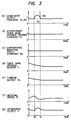
- Fig. 2 shows an example of the rotating speed control unit 16 among the afore-mentioned constituents.
- Numeral 17 denotes a comparator, which delivers a rotating speed deviation ⁇ N as an output.
- the rotating speed deviation ⁇ N is input to a proportional element (K1) 18 and an integral element (K2/S) 19, the outputs of which are added by an adder 20 into the guide vane opening degree correction signal ⁇ Y.
- variable speed hydro-power plant apparatus of the above stated first embodiment of the present invention, as shown in the control circuit arrangement of Fig. 1, a decision unit or signal correction circuit 25 for correcting the generator output signal, an adder 26, a rotating speed correction portion 30, and a limitative reference rotating speed correction or extraction portion 31 are furnished.
- the decision unit 25 includes a signal correction portion for the generator output P.
- the decision unit 25 delivers the generator output correction signal ⁇ P1 in accordance with the guide vane opening degree Y on each occasion, on the basis of N1> N 1p .
- a limitative reference rotating speed N 1p is determined from the input of the guide vane opening degree Y because a limitative reference rotating speed N 1P at a shift to an unstable turbine operation region differs depending upon the guide vane opening degree Y.
- the limitative reference rotating speed correction unit 31 affords an output which varies the generator quantity correction signal ⁇ P1 in accordance with the guide vane opening degree Y.
- the generator output correction signal ⁇ P1 is sampled from the generator output signal correction circuit 25 so as to increase the generator output P, whereas the guide vane opening degree Y at the turbine output side is not corrected at all.
- Such an input/output unbalanced control gives rise to the lowering of the rotating speed N as easily conjectured from the explanation on Fig. 9.
- the above stated first embodiment of the present invention exercises such an unbalanced control when the unstable operation region of the turbine characteristics has been approached.
- a turbine operating point in a state before the point of time 0 lies at a point K in Fig. 4 on the characteristics state 1 as determined by the guide vane opening degree Y and the rotating speed N, and a turbine operating point after the decrease of the generator output P ought to become a point L corresponding to a new guide vane opening degree Y.
- the turbine operating point approaches the limit operation characteristics of the pump turbine, for example the no-load flow rate curve nr , along the characteristics curve 1.
- the present time turbine operating point is grasped on the turbine characteristics diagram of the pump turbine 2, for example, on the various turbine characteristics curves.
- the limit operation characteristics of the pump turbine defined in the present invention is decided in advance, for example, according to the no-load flow rate curve nr or surrounding portions thereof. Such a limit turbine operation characteristics is formed on the no-load flow rate curve nr or in parallel with the no-load flow rate curve nr .
- the limit turbine operation characteristics is to be set the upper limitation of the turbine operating point such as the rotating number per unit head N1 which is located close to but well away from the S-shaped characteristics part.
- a point of time t0 in Fig. 3 indicates a time at which the rotating speed N has reached a speed on the limit characteristics curve nr and becomes to reach at a point M. Therefore, the operating point shifting action is commenced to avoid dropping into the unstable turbine operation region and to bring back to the stable turbine operation region.
- the generator output correction signal ⁇ P1 is output at the point of time t0 in Fig. 3, and only the generator output command P 0′ is influenced by the generator output correction signal ⁇ P1 and is increased. In contrast, the guide vane opening degree command Y a and the rotating speed command N a remain unchanged at constant values.
- the generator output P increases according to the generator output command P 0′ , whereas the guide vane opening degree Y and the turbine output P T which are determined by the guide vane opening degree command Y a do not change.
- the illustrated example shows that the quantities of the appropriate guide vane opening degree Y and the turbine output P T are decreasing toward values which correspond to the alteration at the point of time 0.
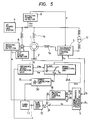
- Fig. 5 shows a second embodiment of the present invention.
- the correction signal is the rotating speed correction signal ⁇ N a corresponding to the rotating speed N. Since the way of evaluating this correction signal in the decision unit 25A is the same as in the first embodiment of the present invention shown in Fig. 1, it shall not be explained here.
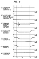
- Fig. 6 shows the wave-forms of various portions in the case where the generator output command P0 decreases at a point of time 0, with the result that the turbine rotating speed N rises and that the decision unit 25A in Fig. 5 detects N1 > N 1p and delivers the rotating speed correction signal ⁇ N a at a point of time t0. Since operations up to the point of time t0 in this figure are the same as in Fig. 3, operations after t0 will be explained here.
- the rotating speed correction signal ⁇ N a acts so as to decrease the appropriate rotating speed command N a , and the corrected rotating speed command N a′ decreases rapidly after the point of time t0.
- the final guide vane opening degree command Y a′ is found in such a way that the appropriate guide vane opening degree command Y a and the guide vane opening degree correction command ⁇ Y obtained according to the corrected rotating speed command N a′ are added by the adder 21.
- variable speed hydro-power plant apparatuses of the first embodiment and the second embodiment of the present invention can be extricated into the stable turbine operation region by lowering the rotating speed of the pump turbine 2, and, and even in the transient stage, the frequency of the A.C. power line system 4 can be held constant.
- the system frequency f is the sum of the frequency f2 of the secondary winding 1b and a frequency f w determined in correspondence with the rotating speed of the pump turbine 2.
- the secondary excitation control unit 3 operates in order to keep the system frequency f constant in such a manner that the frequency f2 decreases or increases by the fluctuating increment or decrement of the frequency f w .
- the present invention is applicable without changing the purport thereof, also to a variable speed generator of the type in which a frequency converter is disposed on the primary side of the generator.
- the present invention is also applicable to a variable speed hydro-power plant apparatus in which the secondary excitation control unit is driven by the composite signal of the generator output command and the rotating speed command, and the opening degree of the guide vane is controlled to the appropriate opening degree for highest efficiency.
- the rotating speed correction control for lowering the rotating speed N of the pump turbine 2 in the particular variable speed hydro-power plant apparatus is performed before, or simultaneously with, the start or output rapid increase operation of the hydraulic machinery. That is, the rotating speed deviation ⁇ N a shown in Fig. 7 is temporarily input at a point of time t11. In other words, the appropriate rotating speed command N a is corrected to (N a - ⁇ N a ).
- the rotating speed N of the pump turbine 2 can be completely corrected to (N a - ⁇ N a ) while the generator output P from the generator 1 holds its original value.
- the turbine mode operation start or output increase operation of the other hydraulic machinery sharing the pipe line may be performed at the point of time t12, or may well be performed during the lowering of the rotating speed N of the particular variable speed machinery before time t12.
- the rotating speed correction control based on the rotating speed deviation ⁇ N a is released to restore the rotating speed N to the original appropriate rotating speed command N a after the rapid opening operation of the other hydraulic machinery has ended, or the water hammering in the shared pipe line has settled sufficiently.
- variable speed hydro-power plant apparatus of the secondary excitation system has been explained
- present invention is also applicable to the variable speed hydro-power plant apparatus of a primary excitation system, namely, of the type in which a frequency converter is located on the primary side of the generator.
Landscapes
- Engineering & Computer Science (AREA)
- Chemical & Material Sciences (AREA)
- Combustion & Propulsion (AREA)
- Mechanical Engineering (AREA)
- General Engineering & Computer Science (AREA)
- Control Of Eletrric Generators (AREA)
- Control Of Water Turbines (AREA)
Description
- The present invention relates to a control system for a variable speed hydro-power plant according to the preamble portion of claim 1.
- The present invention further shows a control system for a variable speed hydro-power plant apparatus realizing a control method well suited to a variable speed pumping-up power plant apparatus which shared an upstream or downstream side pipe line with another hydraulic machinery and which comprises a pump turbine exhibiting an S-shaped characteristics in a turbine or a water turbine operation region.
- A variable speed hydro-power plant apparatus to which the present invention is applied uses a wound-rotor induction generator as an induction machine which is driven by a pump turbine or a water turbine (herein-below, simply termed "pump turbine"), and it excites the secondary winding thereof A.C.-wise through a frequency converter.
- The variable speed hydro-power plant apparatus is therefore noticed owing to the feature that any desired rotating speed of the pump turbine can be established in the state in which the output frequency of the generator is held at an A.C. power line system frequency, so the variable speed hydro-power plant apparatus can be operated at a rotating speed affording a high pump turbine efficiency, or that when the generator is subjected to a variable speed pumping-up operation as a motor, an AFC (automatic frequency control) responsive operation is possible in spite of the operation as a simple constant speed motor.
- Meanwhile, even in the case of the pump turbine of this variable speed hydro-power plant apparatus, a S-shaped characteristics turbine region is involved likewise to a conventional fixed speed pump turbine, and a measure for avoiding the S-shaped characteristics turbine region is indispensable.
- Japanese Patent Application Laid-open No. 72998/1984 has proposed one technique for avoiding the entry of an operation into the unstable turbine operation region of the S-shaped characteristics at the stage of shift from no load to a rated load in the variable speed hydro-power plant apparatus.
- In this prior art, in order to prevent the operating point of the pump turbine from rushing into the S-shaped characteristics turbine region, the guide vane opening degree control of the pump turbine is preferred to a rotating speed control based on the induction generator.
- More specifically, the output of the induction generator is controlled according to a generator output command which is given to the generator, while the opening degree of the guide vane is first led to an opening degree corresponding to the changed generator output command as quickly as possible, and the appropriate rotating speed control is thereafter performed slowly.
- The technique has the effect that the operation can be hindered from entering the unstable turbine operation region of the S-shaped characteristics at the start of the pump turbine.
- In the conventional variable speed hydro-power plant apparatus according to Japanese Patent Laid-Open No. 71497/1987, the situations of fluctuations in the various quantities of the individual parts in the case where the generator output command P₀ is increased are as shown in the section (a) in Fig. 9. It can be understood that, after the change of the generator output command P₀ the various quantities become stable under new operating states. Referring now to Fig. 9, the fluctuations of the various quantities of the individual parts in transient states will be explained.
- The generator output command P₀ is now raised step-wise as shown at the section (a) in Fig. 9, at a point of time t₀ with the intention of raising the generator output P as shown at the section (g) in Fig. 9. Then, the generator output P of the induction generator rises following up the change of the generator output command P₀ as shown at the section (a) in Fig. 9.
- On the other hand, after the generator output command P₀ has been given, the response of the opening degree Y of the guide vane is slower than the response of the generator output P. For this reason, the turbine output PT shown at the section (e) in Fig. 9 becomes smaller than the generator output P, and the rotating speed N shown at the section (f) in Fig. 9 is temporarily decelerated after the sudden change of the generator output command P₀.
- Thereafter, at a point of time t₁, the generator output P and the turbine output PT become equal, and the rotating speed N becomes the minimum. At this time t₁, the rotating speed deviation or correction signal ΔN = (Na - N) is plus, so that the guide vane opening degree deviation or correction signal ΔY = (Ya - Y) is plus, and the guide vane opening degree Y increases more than the appropriate guide vane opening degree command Ya shown at the section (b) in Fig. 9.
- Accordingly, the turbine output PT becomes greater than the generator output P, and the rotating speed N begins to rise as shown at the section (f) in Fig. 9. With the rise of the rotating speed N, the rotating speed deviation ΔN thereof from the appropriate rotating speed command Na decreases, and with the decrease of the guide vane opening degree deviation ΔY, the turbine output PT decreases, and the acceleration of the rotating speed N decreases.
- The rotating speed deviation ΔN in a steady state is rendered zero by the integral element in the rotating speed control unit. On the other hand, the guide vane opening degree deviation ΔY between the appropriate guide vane opening degree command Ya from the turbine characteristics function generation unit and the guide vane opening degree Y corresponds to the error between a characteristics of the pump turbine, and it can be rendered almost zero by enhancing the precision of the function of the turbine characteristics.
- Consequently, the integral element in the rotating speed control unit may generate only the guide vane opening degree deviation ΔY = (Ya - Y) in the steady state.
- The above will be explained again by the use of equations.
- The secondary excitation unit has an integral element etc. built therein for the purpose of adjusting the generator output P to the generator output command P₀. In the steady state,

- Owing to the integral element built in the rotating speed control unit, in the steady state,

- Besides, owing to the guide vane drive unit, in the steady state,

- Moreover, in the steady state, the turbine output PT and the generator output P ought to be equal:

- Further, the appropriate guide vane opening degree command Ya ought to have originally been given so as to correspond to the generator output command P₀ under the water head or effective head H on that occasion and N = Na. Therefore,

- With the above put together, Y = Ya holds, namely, the guide vane opening degree deviation ΔY = 0 holds in the steady state. In the rotating speed control unit, the gain (K₁) of the proportional element having a braking effect is made greater, and the gain (K₂) of the integral element is made relatively smaller, thereby to raise the response rate of the opening degree of the guide vane to the utmost. On the other hand, the turbine output PT and the rotating speed N are set without vibrations as seen from at the sections (a) and (f) in Fig. 9.
- Thus far, the responsive operations of the prior art variable speed hydro-power plant apparatus have been explained. In brief, according to this prior art variable speed hydro-power plant apparatus, the turbine input and the generator output are controlled in balanced fashion, whereby the various quantities can be held stable.
- Now, the unstable operation phenomenon of the pump turbine will be explained.
- In general, the runner and other devices of the pump turbine, especially a high water head pump turbine, are so designed as to demonstrate a sufficient centrifugal pumping action to the end of attaining a high water head during a pumping operation.
- The design, however, adversely affects the operation of the pump turbine. In particular, it is considered inevitable that the turbine characteristics called "S-shaped characteristics" is involved.
- In a case where the characteristics of the pump turbine adopted for this design is indicated by a characteristics curve which expresses the relationship between a rotating speed per unit head (N₁) and a flow rate per unit head (Q₁) under the predetermined opening degree of the guide vane, the characteristics curve has in the operation region of the pump turbine, the first part in which the value of the flow rate per unit head (Q₁) decreases with increase in the value of the rotating speed per unit head (N₁) and the second part in which the value of the flow rate per unit head (Q₁) decreases with decrease in the value of the rotating speed per unit head (N₁).
- In order to facilitate the description, the second part shall be termed "S-shaped characteristics part" in this specification. Further, the characteristics of the pump turbine in the S-shaped characteristics part shall hereinafter be termed the "S-shaped characteristics".
- During the turbine operation in the S-shaped characteristics part, also a torque per unit head (T₁) decreases with the decrease of the rotating speed per unit head (N₁).
- Usually, the operation of the pump turbine is performed in the first part. However, in a case where the rotating speed per unit head (N₁) increases suddenly and greatly due to an abrupt load decrease or the like, there is the possibility that the pump turbine will rush into the S-shaped characteristics part or region. Once the pump turbine has rushed into the S-shaped characteristics part or region, it becomes, in effect, impossible to continue the operation of the variable speed hydro-power plant apparatus.
- The characteristics of the pump turbine having the S-shaped characteristics in the turbine operation region are illustrated in Fig. 10 and Fig. 11. In Fig. 10, the characteristics of the pump turbine is shown as the relationship between the rotating speed per unit head (N₁) and the flow rate per unit head (Q₁) with the guide vane opening degree (Y) taken as a parameter.
- On the other hand, in Fig. 11, the characteristics of the pump turbine is shown as the relationship between the rotating speed per unit head (N₁) and the torque per unit head (T₁) by the use of the same parameter.

- In the above expressions, symbols N, Q, H and T denote the rotating speed, the flow rate, the effective head and the torque of the pump turbine, respectively.
- Characteristics curves 1 and 1′ are obtained under a comparatively great guide vane opening degree as predetermined.
Characteristics curves Characteristics curves - In the part a-d-h of the characteristics curve 1, the value of the flow rate per unit head (Q₁) decreases with the decrease of the rotating speed per unit head (N₁). As stated above, this curve part a-d-h is termed as the "S-shaped characteristics part" in this specification.
- Similarly, a curve part b-e-i is the S-shaped characteristics part of the
characteristics curve 2, and a curve part c-f-j is that of thecharacteristics curve 3. Such S-shaped characteristics turbine regions shift to the higher the rotating speed per unit head (N₁) side as the guide vanes become larger. - Likewise to the curve parts in Fig. 10, also in Fig. 11, curve parts a′-d′-h′, b′-e′-i′ and c′-f′-j′ are the S-shaped characteristics parts of the characteristics curves 1′, 2′ and 3′, respectively.
- Fig. 11 has close relations with Fig. 10. For example, a point x meeting Q₁ = Q1x and N₁ = N1x on the
characteristics curve 3 in Fig. 10 corresponds to a point x′ on thecharacteristics curve 3′ in Fig. 11. The point x′ is a point meeting T₁ = T1x′ and N₁ = N1x′ (= N1x). Similarly, points a, b, c, d, e, f, h, i, and j in Fig. 10 correspond to a′, b′, c′, d′, e′, f′, h′, i′ and j′ in Fig 11, respectively. - A curve nr is a no-load flow rate curve. The intersection points α, β and γ between the
characteristics curves - The variable speed hydro-power plant apparatus is operated under conditions differing every moment, and it is sufficiently presumed that the operation approaches or enters the unstable turbine operation region during an ordinary operation except the start operation. Nevertheless, the above stated prior art is not effective as a measure of avoidance and extrication in this case.
- Again, in the above stated Japanese Patent Laid-Open No. 72998/1984, while the output of the generator is controlled according to a generator output command given to the generator, the opening degree of guide vane is led to an opening degree corresponding to the changed generator output as quickly as possible, and the appropriate control of a rotating speed is thereafter performed slowly.
- In actuality, however, the control rate of the guide vane opening degree is inevitably limited when abnormal water hammering should arise in a waterway upstream or downstream of the pump turbine, and it can never be raised up to the response rate level of the generator output control.
- On the other hand, suppressing the response rate of the generator output control is none other than sacrificing the degree of contribution of the variable speed hydro-power plant apparatus to an electric power system and is truly unfavorable. As a result, it is proper to consider that the rotating speed greatly fluctuates transiently. That is, in the above stated prior art, the rotating speed lowers when the load increases, and it rises when the load decreases.
- Assuming now that the operating point (for example, the rotating speed per unit head N₁ = N/√H) of the pump turbine before the load change lies near the S-shaped characteristics turbine operation region, there is no problem at the load increase because the turbine operating point moves in the direction of coming away from the S-shaped characteristics turbine operation region while accompanying the lowering of the rotating speed.
- To the contrary, at the load decrease, the turbine operating point comes nearer while accompanying the rise of the rotating speed, and it can rush into the S-shaped characteristics turbine operation region in some cases.
- Once the turbine operating point has rushed into the S-shaped characteristics turbine operation region, the torque of the pump turbine lowers rapidly and greatly together with the flow rate of water, and the rotating speed lowers rapidly. At this turbine operating point of time, it becomes, in effect, impossible to continue the normal operation of the variable speed hydro-power plant apparatus.
- Further, notice needs to be taken of the fact that the above state inrush of the turbine operating point into the S-shaped characteristics turbine operation region does not take place due to only the transient change of the rotating speed (N). The rotating speed per unit head N₁ = N/√H increases also when the effective head (H) has lowered for any reason.
- Especially in a case where the upstream or downstream pipe line of the pump turbine is shared with another water turbine or pump turbine, the water hammering phenomenon which has arisen in the other water turbine or pump turbine is propagated through the shared pipe line. Accordingly, even when only the variable speed hydro-power plant apparatus is perfectly controlled, there is the potential that the problem stated above will be posed by another apparatus.
- Japanese Patent Laid-Open No. 164080/1986 proposes a method in which, when a variable speed hydro-power plant apparatus is to be put on an electric power system, the rotating speed is set at the minimum value allowable under the effective head (H) on that occasion, whereby the induction generator is stably put on the electric power system without the influence of the S-shaped characteristics turbine operation region.
- However, nothing is referred to as regards a method of avoiding inrush into the S-shaped characteristics turbine operation region, the method being effective after putting the unit on the electric power system. In particular, in the variable speed hydro-power plant apparatus, the rotating speed is quite independent of the frequency of the electric power system unlike those of a fixed speed apparatus (a synchronous generator).
- That is, a synchronizing torque from the electric power system cannot be expected. In other words, even after putting on the electric power system, just as before it, the control of the rotating speed must be rendered satisfactory by the variable speed hydro-power plant apparatus itself. In this respect, Japanese Patent Laid-Open No. 164080/1986 is incomplete.
- US-A-4 382 745 shows a method of controlling the opening and closing of wicked gates of a pump turbine, if the same drops into the S-shaped area of the turbine performance. If this is the case, the wicked gates are controlled to open when it is detected that discharge per unit head decreases with the reduction of speed per unit head. When it is once detected that the ratio of variation in the discharge per unit head to the variation in the speed per unit head is reversed from a positive value to a negative value, the wicked gates are closed. With only the opening of the wicked gates as input to the process of the turbine control system, the reaction is too slow to safely avoid a dropping into the S-shaped area, e.g. if a sudden drop or a sudden rise of the waterline pressure occurs.
- The present invention consists in eliminating the afore-mentioned disadvantages of the prior art techniques, and providing a simple and reliable method of controlling a variable speed hydro-power plant apparatus in which, even when the influence of water hammering is exerted from another hydraulic machinery sharing a pipe line, a turbine operating point N₁ = N/√H (where N denotes a rotating speed, and H an effective head) is prevented from abnormally approaching the S-shaped characteristics turbine operation region.
- The object of the present invention is to provide a control system for a variable speed hydro-power plant wherein the continuation of a stable and reliable turbine operation can be guaranteed.
- The object is solved according to the features of claim 1. The dependent claims show advantageous embodiments and further developments of the invention.
- The present invention shall realize a control system for a variable speed hydro-power plant apparatus wherein, when the turbine operation approaches the unstable turbine operation region, such an unstable turbine operation region can be brought back to a stable turbine operation region, and a drop into the S-shaped characteristics turbine operation region can be avoided, in spite of the interference of the water hammering from another hydraulic machinery sharing a pipe.
- In the present invention, a current turbine operating point is grasped on the turbine characteristics diagram of the pump turbine, and when it has approached the unstable turbine operation region, the rotating speed of the pump turbine is forcibly lowered.
- As a practicable measure for lowering the rotating speed, a frequency converter is controlled so as to increase the output of the generator, or the opening degree of the guide vane is controlled so as to decrease the output of the pump turbine, thereby to lower the rotating speed of the pump turbine.
- According to the present invention, a variable speed hydro-power plant apparatus comprises a generator connected to an electric power system which is provided with a frequency converter in order to generate power of the same terminal frequency as that of the electric power system independently of its rotor driving speed, and a pump turbine which is directly coupled to a shaft of the generator rotor and which includes variable guide vanes.
- According to the present invention, a variable speed hydro-power plant apparatus comprises a generator whose primary winding is connected to an electric power system and whose secondary winding is connected to the electric power system through a secondary excitation control unit, and a pump turbine which is directly coupled to a shaft of the generator rotor and which includes variable guide vanes.
- Upon detecting an approach of a turbine operating point of the variable speed hydro-power plant apparatus to an unstable turbine operation region, the present invention attains by one of the following control methods, namely, (1) a rotating speed of the pump turbine is lowered, (2) a mechanical output of the pump turbine is made smaller than an output of the generator, (3) only the generator output is increased through the generator output controller so as to make a mechanical output of the turbine smaller than the generator output, and (4) only a mechanical output of the turbine is decreased through the turbine controller so as to make the mechanical output of the turbine smaller than the generator output.
- In order to detect an approach of a turbine operating point of the variable speed hydro-power plant apparatus to an unstable turbine operation region, a rotating speed per unit head and a reference rotating speed per unit head representing allowable maximum speed which is a function of opening degree of the variable guide vane are compared, whereupon a rotating speed of the pump turbine is lowered.
- In the characteristics of the pump turbine, a stable operation side is a region in which the rotating speed of the pump turbine is not excessively high, and a return to the stable turbine operation side is permitted by lowering the rotating speed of the pump turbine in the variable speed hydro-power plant apparatus in which the rotating speed can be selected separately from and independently of a system frequency.
- Since the pump turbine is accelerated or decelerated on the basis of the difference between mechanical output of the turbine and the generator output, it is effective to increase the generator output or decrease mechanical output of the turbine when a rotating speed of the pump turbine is to be lowered back and kept away from the unstable region.
- The effect of the present invention resides in that, in an ordinary variable speed hydro-power plant mode in which a generator is put on an electric power system, the possibility of the inrush of a pump turbine or a water turbine into a S-shaped characteristics turbine operation region is perfectly eliminated, so the continuation of a stable and reliable turbine operation can be guaranteed.
- At the change of the operating state of the other hydraulic machinery sharing the pipe line, especially at the start of the other hydraulic machinery in a turbine mode operation or at the mechanical output rapid increase operation thereof, also when the effective head of the particular variable speed pump turbine drops temporarily to increase the rotating number per unit head by the water hammering phenomenon in the shared pipe line, the rotating speed of the pump turbine of the particular variable speed hydro-power plant apparatus is temporarily lowered and corrected before, or concurrently with, the start or output rapid increase operation of the other side hydraulic machinery.
- Then, after the danger of the interference of the water hammering in the shared pipe line attributed to the hydraulic machinery has been evaded, the rotating speed correction control of the concerned variable speed hydro-power plant is removed, and its rotating speed is restored to the original appropriate value.
- According to the present invention, in a turbine mode operation of a variable speed hydro-power plant sharing an upstream or downstream side pipe line with another hydraulic machinery, the variable speed hydro-power plant apparatus comprises a pump turbine which exhibits a S-shaped characteristics in a turbine operation region and includes variable guide vanes, and a generator with a frequency converter, which is so constructed as to generate electric power thereof equal in frequency to that of an electric power system in spite of the fact that a rotating speed of the pump turbine is changed in conformity with an operating state.
- In case of abruptly changing an operating state of the other side hydraulic machinery with which the upstream or downstream side pipe line is shared, the rotating speed of the variable speed hydro-power plant apparatus is temporarily corrected and controlled, and the temporary rotating speed correction control is released after water hammering in the shared pipe line caused by the abrupt change of the operating state of the other side hydraulic machinery has settled down.
- When the other side hydraulic machinery with which the upstream or downstream side pipe line is shared is to start or rapidly increase its output in the turbine mode operation, the rotating speed correction control of lowering the rotating speed of the variable speed hydro-power plant apparatus is performed before-hand, or the rotating speed correction control is validated in a limited specified operation region in accordance with a water head or a rotating speed of the pump turbine or an opening degree of the guide vane on each occasion.
- When the other side hydraulic machinery with which the upstream or downstream side pipe line is shared is to start or operate so as to rapidly increase its output in a turbine mode operation, the rotating speed correction control of lowering the rotating speed of the variable speed hydro-power plant apparatus is simultaneously performed, or the rotating speed correction control is validated in a limited specified operation region in accordance with a water head or a rotating speed of the pump turbine or an opening degree of the guide vane on each occasion.
- Influence ascribable to the change of the operating state of the other side hydraulic machinery sharing the pipe line, namely, the lowering of the effective head of the particular variable speed pumping-up plant apparatus ascribable to the water hammering is calculatedly obtained before-hand, and the rotating speed of the hydraulic machinery of the particular variable speed pump turbine plant apparatus is lowered and corrected to the extent that the raise of the rotating speed per unit head attendant upon the lowering of the effective head is cancelled.
- The rotating speed lowering correction may be made previously to a command for changing the operating state of the other side hydraulic machinery, or it may well be made simultaneously at that time.
- The effect of the present invention consists in providing a proper and simple control method which reliably avoids a drop into a S-shaped characteristics turbine operation region threatening the continuous operation of a generator mode operation, in spite of the interference of water hammering phenomenon from another side hydraulic machinery sharing a pipe line.
- Further, there is such an effect that the operable range of the rotating speed and the operable range of the effective head of a particular variable speed pump turbine plant apparatus can be widened. Even when the operable ranges are widened, the danger of the drop into the S-shaped characteristics turbine operation region is not involved.
-
- Fig. 1 is a block diagram of a control system of a variable speed hydro-power plant apparatus according to a first embodiment of the present invention;
- Fig. 2 is a block diagram of a rotating speed control unit used in Fig. 1;
- Fig. 3 is an explanatory diagram showing the signals of the various parts of the control units in Fig. 1 and illustrates at the sections (a) through (g) signal wave-forms developing in Fig. 1;
- Fig. 4 is a diagram showing the graph of the flow rate characteristics (N₁ - Q₁) of a pump turbine having a S-shaped characteristics according to the first embodiment of the present invention;
- Fig. 5 is a block diagram of a control system of a variable speed hydro-power plant apparatus according to a second embodiment of the present invention;
- Fig. 6 is an explanatory diagram showing the signals of the various parts of the control units in Fig. 5 and illustrates at the sections (a) through (g) signal wave-forms developing in Fig. 5;
- Fig. 7 is a block diagram of a control system of a variable speed hydro-power plant apparatus according to a third embodiment of the present invention;
- Fig. 8 is an explanatory diagram showing the signals of the various parts of the control units in Fig. 7 and illustrates at the sections (a) through (g) signal wave-forms developing in Fig. 7;
- Fig. 9 is an explanatory diagram showing the signals of the various parts of the control units in prior art and illustrates at the sections (a) through (g) signal wave-forms;
- Fig. 10 is a diagram showing the graph of the flow rate characteristics (N₁ - Q₁) of a pump turbine having a S-shaped characteristics part; and
- Fig. 11 is a diagram showing the graph of the torque characteristics (N₁ - T₁) of a pump turbine having a S-shaped characteristics part.
- A variable speed hydro-power plant apparatus according to various embodiments of the present invention will be described with reference to the drawings. Among them, a first embodiment shown in Fig. 1 consists in that a stable turbine operation side is restored by increasing the output of a generator when such need arises. The variable speed hydro-power plant apparatus and control devices therefor will be explained.
- Referring to Fig. 1, numeral 1 designates an induction machine or induction generator which is driven and rotated by a
pump turbine 2 directly coupled to the rotor thereof and in a turbine mode. - Also, the induction generator 1 is subjected to a variable speed operation in such a manner that a secondary winding 1b of the induction generator 1 is supplied with an alternating exciting current which is adjusted to a predetermined frequency in accordance with the rotating speed of the induction generator 1 by means of a secondary
excitation control unit 3 including a frequency converter, while A.C. power at a frequency equal to the frequency of an A.C.power line system 4 is delivered from a primary winding 1a of the induction generator 1.Numeral 12 indicates an exciting transformer. - The variable speed hydro-power plant apparatus is schematically constructed as stated above. One of the control terminals of the variable speed hydro-power plant apparatus is the secondary
excitation control unit 3. Aslip phase detector 7 is provided for the control of the secondaryexcitation control unit 3, and it is used for detecting a slip phase signal Sp which is equal to the difference between the voltage phase of the A.C.power line system 4 and the rotating phase of the secondary side of the induction generator 1 in terms of an electrical angle. - The rotor of the
slip phase detector 7 is provided with a three phase which is connected in parallel with the primary winding 1a of the induction generator 1, and on the stator side of theslip phase detector 7, Hall converters are respectively disposed at positions differing by an electrical angle of π/2. Whereby the coincident signal of the voltage phase of the A.C.power line system 4 as viewed from the secondary side of the induction generator 1 is detected and converted into the slip phase signal Sp by the Hall converters. - In addition, an
effective power detector 9 is provided for the control of the secondaryexcitation control unit 3, and a generator output or an effective power P is applied as a feedback signal for a generator output command P₀. - The generator output command P₀ and the slip phase signal Sp are inputted to the secondary
excitation control unit 3, by which the alternating exciting current to be supplied to the secondary winding 1b of the induction generator 1 is controlled so that the generator output detection signal P of the induction generator 1 to be detected by theeffective power detector 9 may become equal to the generator output command P₀. - The other control terminal of the variable speed hydro-power plant apparatus is
variable guide vanes 11 of thepump turbine 2. - Next, the control units of these control terminals will be explained.
Numeral 5 indicates a pump turbine characteristics function generating unit which generates an appropriate guide vane opening degree command Ya and an appropriate rotating speed command Na on the basis of a generator output command P₀ and a water head signal H from outside. Incidentally, it is also possible to omit the water head signal H in a case where the water head fluctuations are small. -
Numeral 16 indicates a rotating speed control unit, which compares the appropriate rotating speed command Na and the rotating speed signal N detected by arotating speed detector 6, so as to deliver a guide vane opening degree correction signal ΔY. Besides, the guide vane opening degree correction signal ΔY is added to the appropriate guide vane opening degree command Ya at anadder 21, and the resultant signal is input to a guidevane drive unit 10 so as to adjust the opening degree of theguide vane 11 in accordance therewith, whereby a turbine output PT is controlled. - Fig. 2 shows an example of the rotating
speed control unit 16 among the afore-mentioned constituents.Numeral 17 denotes a comparator, which delivers a rotating speed deviation ΔN as an output. The rotating speed deviation ΔN is input to a proportional element (K₁) 18 and an integral element (K₂/S) 19, the outputs of which are added by anadder 20 into the guide vane opening degree correction signal ΔY. - In the variable speed hydro-power plant apparatus of the above stated first embodiment of the present invention, as shown in the control circuit arrangement of Fig. 1, a decision unit or
signal correction circuit 25 for correcting the generator output signal, anadder 26, a rotatingspeed correction portion 30, and a limitative reference rotating speed correction orextraction portion 31 are furnished. - The
decision unit 25 includes a signal correction portion for the generator output P. Thedecision unit 25 delivers the generator output correction signal ΔP₁ in accordance with the guide vane opening degree Y on each occasion, on the basis of N₁> N1p. - At the rotating
speed correction unit 30, in which the actual rotating speed N is divided by the square root of an effective head H so as to obtain the rotating number per unit head N₁. This rotating number per unit head N₁ corresponds to the axis of abscissas in Fig. 10. - On the other hand, in the limitative reference rotating
speed correction unit 31, a limitative reference rotating speed N1p is determined from the input of the guide vane opening degree Y because a limitative reference rotating speed N1P at a shift to an unstable turbine operation region differs depending upon the guide vane opening degree Y. Besides, the limitative reference rotatingspeed correction unit 31 affords an output which varies the generator quantity correction signal ΔP₁ in accordance with the guide vane opening degree Y. - The generator output correction signal ΔP₁ is sampled from the generator output
signal correction circuit 25 so as to increase the generator output P, whereas the guide vane opening degree Y at the turbine output side is not corrected at all. Such an input/output unbalanced control gives rise to the lowering of the rotating speed N as easily conjectured from the explanation on Fig. 9. The above stated first embodiment of the present invention exercises such an unbalanced control when the unstable operation region of the turbine characteristics has been approached. - Next, it will be elucidated that the inrush into the unstable turbine operation region can be prevented by the first embodiment of the present invention shown in Fig. 1. When the generator output command P₀ is decreased suddenly at a point of
time 0 in Fig. 3 showing the quantities of states of the various portions in Fig. 1, the appropriate guide vane opening degree command Ya and the appropriate rotating speed command Na are also decreased, with the result that the guide vane opening degree Y, the turbine output PT and the generator output P are also decreased. - Since, however, the decreasing rate of the generator output P is higher than that of the turbine output PT, and accelerating force due to the rotating parts such as the pump turbine and the rotor acts, and the rotating speed N rises transiently.
- Meanwhile, a turbine operating point in a state before the point of
time 0 lies at a point K in Fig. 4 on the characteristics state 1 as determined by the guide vane opening degree Y and the rotating speed N, and a turbine operating point after the decrease of the generator output P ought to become a point L corresponding to a new guide vane opening degree Y. - Since, however, the change of the guide vane opening degree Y is comparatively slow and the rotating speed N increases rapidly, the turbine operating point approaches the limit operation characteristics of the pump turbine, for example the no-load flow rate curve nr, along the characteristics curve 1.
- In the above stated first embodiment of the present invention, the present time turbine operating point is grasped on the turbine characteristics diagram of the
pump turbine 2, for example, on the various turbine characteristics curves. - The limit operation characteristics of the pump turbine defined in the present invention is decided in advance, for example, according to the no-load flow rate curve nr or surrounding portions thereof. Such a limit turbine operation characteristics is formed on the no-load flow rate curve nr or in parallel with the no-load flow rate curve nr. The limit turbine operation characteristics is to be set the upper limitation of the turbine operating point such as the rotating number per unit head N₁ which is located close to but well away from the S-shaped characteristics part.
- A point of time t₀ in Fig. 3 indicates a time at which the rotating speed N has reached a speed on the limit characteristics curve nr and becomes to reach at a point M. Therefore, the operating point shifting action is commenced to avoid dropping into the unstable turbine operation region and to bring back to the stable turbine operation region.
- The generator output correction signal ΔP₁ is output at the point of time t₀ in Fig. 3, and only the generator output command P0′ is influenced by the generator output correction signal ΔP₁ and is increased. In contrast, the guide vane opening degree command Ya and the rotating speed command Na remain unchanged at constant values.
- As a result, the generator output P increases according to the generator output command P0′, whereas the guide vane opening degree Y and the turbine output PT which are determined by the guide vane opening degree command Ya do not change. The illustrated example, however, shows that the quantities of the appropriate guide vane opening degree Y and the turbine output PT are decreasing toward values which correspond to the alteration at the point of
time 0. - Therefore, the turbine output PT and the generator output P become P > PT, and a decelerating torque acts on the
pump turbine 2 and rapidly lowers the rotating speed N of thepump turbine 2. N₁ < N1p is held by the lowering of the rotating speed N, and thedecision unit 25 restores ΔP₁ = 0. Therefore, the variable speed hydro-power plant apparatus in Fig. 1 is eventually stabilized with the quantities which correspond to the output after the lowering at the point oftime 0. A turbine operating point after the stabilization becomes the point L in Fig. 4. - Fig. 5 shows a second embodiment of the present invention. The output of the decision unit or
signal correction circuit 25A is applied to the appropriate rotating speed command Na, and the guide vane opening degree Y is finally controlled according to the corrected rotating speed command Na′ = Na - ΔNa. - In this case, the correction signal is the rotating speed correction signal ΔNa corresponding to the rotating speed N. Since the way of evaluating this correction signal in the
decision unit 25A is the same as in the first embodiment of the present invention shown in Fig. 1, it shall not be explained here. - Fig. 6 shows the wave-forms of various portions in the case where the generator output command P₀ decreases at a point of
time 0, with the result that the turbine rotating speed N rises and that thedecision unit 25A in Fig. 5 detects N₁ > N1p and delivers the rotating speed correction signal ΔNa at a point of time t₀. Since operations up to the point of time t₀ in this figure are the same as in Fig. 3, operations after t₀ will be explained here. - First, the rotating speed correction signal ΔNa acts so as to decrease the appropriate rotating speed command Na, and the corrected rotating speed command Na′ decreases rapidly after the point of time t₀. In addition, the final guide vane opening degree command Ya′ is found in such a way that the appropriate guide vane opening degree command Ya and the guide vane opening degree correction command ΔY obtained according to the corrected rotating speed command Na′ are added by the
adder 21. - Owing to the decrease of the corrected rotating speed command Na′, therefore, also the final guide vane opening degree command Ya′ throttles the guide vane opening degree Y rapidly. As a result, the turbine output PT decreases rapidly. In contrast, as regards the side of the generator output command P₀, this generator output command P₀ and the actual generator output P remain unchanged because the rotating speed correction signal ΔNa for avoiding the inrush into the unstable turbine operation region does not act on the generator output command P₀ at all.
- As a result, the turbine output PT and the generator output P after the point of time t₀ become P > PT, a decelerating torque acts on the
pump turbine 2 to lower the rotating speed N thereof, and the operation is extricated into the stable turbine operation region as stated in connection with Fig. 10. By the way, when N₁ < N1p has held owing to the lowering of the rotating speed N, the rotating speed correction signal ΔNa becomes extinct, and the various quantities of the portions of the circuit arrangement in Fig. 5 are stabilized at values corresponding to the generator output command P₀. - As described above in detail, the variable speed hydro-power plant apparatuses of the first embodiment and the second embodiment of the present invention can be extricated into the stable turbine operation region by lowering the rotating speed of the
pump turbine 2, and, and even in the transient stage, the frequency of the A.C.power line system 4 can be held constant. - More specifically, the system frequency f is the sum of the frequency f₂ of the secondary winding 1b and a frequency fw determined in correspondence with the rotating speed of the
pump turbine 2. In this regard, the secondaryexcitation control unit 3 operates in order to keep the system frequency f constant in such a manner that the frequency f₂ decreases or increases by the fluctuating increment or decrement of the frequency fw. - Next, modifications to which the present invention is applicable will be explained. Although, in the foregoing, the case of using the induction generator as a variable speed generator has been explained, the present invention is applicable without changing the purport thereof, also to a variable speed generator of the type in which a frequency converter is disposed on the primary side of the generator.
- Besides, the present invention is also applicable to a variable speed hydro-power plant apparatus in which the secondary excitation control unit is driven by the composite signal of the generator output command and the rotating speed command, and the opening degree of the guide vane is controlled to the appropriate opening degree for highest efficiency.
- A third embodiment of the present invention will be explained with reference to Figs. 7 and 8.
- When another hydraulic machinery sharing the upstream or downstream side pipe line is started in a turbine mode operation or is subjected to the operation of rapidly increasing an output, the water hammering phenomenon thereof is propagated through the shared pipe line, and hence, the effective head H of the particular variable speed hydro-power plant apparatus lowers.
- Therefore, the rotating speed correction control for lowering the rotating speed N of the
pump turbine 2 in the particular variable speed hydro-power plant apparatus is performed before, or simultaneously with, the start or output rapid increase operation of the hydraulic machinery. That is, the rotating speed deviation ΔNa shown in Fig. 7 is temporarily input at a point of time t₁₁. In other words, the appropriate rotating speed command Na is corrected to (Na - ΔNa). - The situations of the responses of the combined rotating speed command (Na - ΔNa), the guide vane opening degree Y, the turbine output PT, the rotating speed N, etc. on this occasion are illustrated in Fig. 8.
- At a point of time t₁₂, the rotating speed N of the
pump turbine 2 can be completely corrected to (Na - ΔNa) while the generator output P from the generator 1 holds its original value. - The turbine mode operation start or output increase operation of the other hydraulic machinery sharing the pipe line may be performed at the point of time t₁₂, or may well be performed during the lowering of the rotating speed N of the particular variable speed machinery before time t₁₂.
- Subsequently, at a point of time t₁₃, the rotating speed correction control based on the rotating speed deviation ΔNa is released to restore the rotating speed N to the original appropriate rotating speed command Na after the rapid opening operation of the other hydraulic machinery has ended, or the water hammering in the shared pipe line has settled sufficiently.
- Although, in the above stated third embodiment of the present invention, the variable speed hydro-power plant apparatus of the secondary excitation system has been explained, the present invention is also applicable to the variable speed hydro-power plant apparatus of a primary excitation system, namely, of the type in which a frequency converter is located on the primary side of the generator.
Claims (10)
- Method for controlling a variable speed hydro-power plant comprising:- a pump turbine (2) with an S-shaped characteristic in a turbine operation region,- guide vanes (11) for the pump turbine (2),- a generator (1) driven by and coupled with the pump turbine (2) and having a frequency converter connected to an electrical power system (4),characterized in that- a generator control unit (3) decreases the turbine speed (N) by increasing the output (P) of the generator (1) over the mechanical output (PT) of the pump turbine (2), if the detected turbine speed (N) of the pump turbine (2) is higher than a predetermined reference turbine speed being a function of the opening (Y) of the guide vanes (11), indicating an approach to the S-shaped characteristic.
- Method according to claim 1,
characterized in that
an approach of the operation point of the pump turbine (2) to the S-shaped characteristic is detected monitoring the turbine speed (N) per unit head exceeding a predetermined reference value. - Method according to claim 1 or 2,
characterized in that
the turbine speed (N) per unit head is detected by a rotation speed detector (6). - Method according to claims 1 to 3,
characterized in that
a speed modification control has a detection function for the current operation state and a calculation function for the location of the S-shaped characteristic on the turbine characteristic curve under a current guide vane opening (Y). - Method according to claims 1 to 4,
characterized in that
a no-load flow rate curve (nr) for locating the S-shaped characteristic is determined and upon detecting an approach of the turbine operation state to the no-load flow rate curve (nr) of the pump turbine (2), the mechanical output (PT) of the pump turbine (2) is made smaller than the output (P) of the generator (1). - Method according to claims 1 to 5,
characterized in that
upon detecting an approach of the turbine operation state to the no-load flow rate curve (nr) of the pump turbine (2), the generator output (P) is increased by the generator output controller (26) so as to make the turbine output (PT) smaller than the generator output (P). - Method according to claims 1 to 6,
characterized in that
in case of an abrupt change of an operation state of another hydraulic machinery with which the upstream or downstream side pipe line is shared, the rotating speed (N) is temporarily corrected and controlled and the temporary rotating speed correction control is released after water hammering in the shared pipe line attendant upon the abrupt change of the operation state of the other hydraulic machinery has settled down. - Method according to claims 1 to 7,
characterized in that
when the other hydraulic machinery starts or rapidly increases its output during a turbine mode operation, the rotating speed correction control of lowering the rotating speed (N) is performed beforehand. - Method according to claims 1 to 8,
characterized in that
when the other hydraulic machinery starts or operates so as to rapidly increase its output during a turbine mode operation, the rotating speed correction control of lowering the rotating speed (N) is simultaneously performed. - Apparatus for controlling a variable speed hydro-power plant comprising:- a pump turbine (2) with an S-shaped characteristic in a turbine operation region,- guide vanes (11) for the pump turbine (2),- a generator (1) driven by and coupled with the pump turbine (2) and having a frequency converter connected to an electrical power system (4),characterized in thatdetection means is provided for detecting the turbine speed (N) of the pump turbine (2),indication means is provided for indicating an approach to the S-shaped characteristic, when the detected turbine speed (N) is higher than a predetermined reference turbine speed being a function of the opening (Y) of the guide vanes (11) anda generator control unit (3) is provided reacting to said indication means for decreasing the turbine speed (N) by increasing the output (P) of the generator (1) over the mechanical output (PT) of the pump turbine (2).
Applications Claiming Priority (4)
| Application Number | Priority Date | Filing Date | Title |
|---|---|---|---|
| JP201712/87 | 1987-08-14 | ||
| JP62201712A JPH0636680B2 (en) | 1987-08-14 | 1987-08-14 | Variable speed generator |
| JP62318851A JP2753239B2 (en) | 1987-12-18 | 1987-12-18 | Variable speed power plant |
| JP318851/87 | 1987-12-18 |
Publications (3)
| Publication Number | Publication Date |
|---|---|
| EP0303170A2 EP0303170A2 (en) | 1989-02-15 |
| EP0303170A3 EP0303170A3 (en) | 1990-05-23 |
| EP0303170B1 true EP0303170B1 (en) | 1996-05-15 |
Family
ID=26512946
Family Applications (1)
| Application Number | Title | Priority Date | Filing Date |
|---|---|---|---|
| EP88112625A Expired - Lifetime EP0303170B1 (en) | 1987-08-14 | 1988-08-03 | Control system for a variable speed hydro-power plant apparatus |
Country Status (4)
| Country | Link |
|---|---|
| US (1) | US4920277A (en) |
| EP (1) | EP0303170B1 (en) |
| KR (1) | KR920007517B1 (en) |
| DE (1) | DE3855290T2 (en) |
Cited By (1)
| Publication number | Priority date | Publication date | Assignee | Title |
|---|---|---|---|---|
| CN112383254A (en) * | 2020-12-07 | 2021-02-19 | 中国长江电力股份有限公司 | Guide vane opening degree analog quantity segmentation open-loop control method and system |
Families Citing this family (35)
| Publication number | Priority date | Publication date | Assignee | Title |
|---|---|---|---|---|
| JP3144451B2 (en) * | 1993-12-24 | 2001-03-12 | 株式会社日立製作所 | Variable speed pumped storage generator |
| US5742515A (en) * | 1995-04-21 | 1998-04-21 | General Electric Co. | Asynchronous conversion method and apparatus for use with variable speed turbine hydroelectric generation |
| US5953225A (en) * | 1995-04-21 | 1999-09-14 | General Electric Co. | Power flow control and power recovery with rotary transformers |
| US5952816A (en) * | 1995-04-21 | 1999-09-14 | General Electric Co. | Compensation for power transfer systems using variable rotary transformer |
| CA2174568C (en) | 1995-04-21 | 2009-11-17 | Mark A. Runkle | Interconnection system for transmitting power between electrical systems |
| US5841267A (en) * | 1995-04-21 | 1998-11-24 | General Electric Co. | Power flow control with rotary transformers |
| ES2233979T3 (en) * | 1995-10-31 | 2005-06-16 | General Electric Company | PROCEDURE AND ASynchronous CONVERTER APPARATUS FOR THE GENERATION OF HYDROELECTRIC ENERGY WITH VARIABLE SPEED TURBINE. |
| US5864183A (en) * | 1996-08-28 | 1999-01-26 | Voith Hydro, Inc. | Method and apparatus for optimizing performance of a pump-turbine |
| DE19717492A1 (en) * | 1997-04-25 | 1998-11-12 | Weismann Martin | Optimising efficiency of hydroelectric power station |
| DE19719406C1 (en) * | 1997-05-12 | 1998-11-19 | Voith Hydro Gmbh & Co Kg | Method for operating a hydraulic machine |
| JP3558919B2 (en) * | 1999-04-14 | 2004-08-25 | 三菱電機株式会社 | Excitation control device and excitation control method |
| CN1370346A (en) * | 2000-06-19 | 2002-09-18 | 三菱电机株式会社 | Excitation control device and excitation control method |
| US6456021B1 (en) | 2000-06-30 | 2002-09-24 | General Electric Company | Rotating variable frequency transformer with high voltage cables |
| US6465926B2 (en) | 2000-06-30 | 2002-10-15 | General Electric Company | Cleaning/cooling of high-power rotary current collector system |
| US6469414B2 (en) | 2000-06-30 | 2002-10-22 | General Electric Company | Slip-ring mounting assembly for high-power rotary current collector system |
| CA2351895C (en) | 2000-06-30 | 2009-12-15 | General Electric Company | Slip-ring mounting assembly for high-power rotary current collector system |
| CA2413571C (en) * | 2002-12-05 | 2010-03-30 | General Electric Canada Inc. | Ship lock electrical energy generation |
| JP4073776B2 (en) * | 2002-12-19 | 2008-04-09 | 三菱電機株式会社 | Excitation control device |
| JP3918837B2 (en) | 2004-08-06 | 2007-05-23 | 株式会社日立製作所 | Wind power generator |
| EP1679787A1 (en) * | 2005-01-07 | 2006-07-12 | Siemens Aktiengesellschaft | Current generator and method for generation of current of predetermined line frequency |
| US7053498B1 (en) * | 2005-01-18 | 2006-05-30 | Wartron Corporation | Electronic control for a hydraulically driven generator |
| US8269359B2 (en) * | 2006-01-17 | 2012-09-18 | Uusi, Llc | Electronic control for a hydraulically driven generator |
| US7759811B2 (en) * | 2006-01-17 | 2010-07-20 | Nartron Corporation | Electronic control for a hydraulically driven generator |
| US8269360B2 (en) * | 2006-01-17 | 2012-09-18 | Uusi, Llc | Electronic control for a hydraulically driven auxiliary power source |
| JP4480777B2 (en) * | 2008-06-04 | 2010-06-16 | 三菱電機株式会社 | Variable speed synchronous generator motor |
| US8112184B2 (en) * | 2009-03-06 | 2012-02-07 | Hamilton Sundstrand Corporation | Auxiliary power unit with dual use of speed signals |
| DE102011114438A1 (en) * | 2011-09-28 | 2013-03-28 | Voith Patent Gmbh | Hydraulic power plant i.e. tidal power plant, operating method, involves separately summing power unit outputs produced at generator for torque/rotation speed curves, and performing adaptive tracking of curves based on summed outputs |
| JP6220241B2 (en) * | 2013-01-11 | 2017-10-25 | 株式会社東芝 | Control device and control method for variable speed pumped storage power generation system |
| EP2980399A1 (en) * | 2014-07-29 | 2016-02-03 | ALSTOM Renewable Technologies | Method for stabilizing the rotation speed of a hydraulic machine with s-characteristics and installation for converting hydraulic energy into electrical energy |
| PT2995808T (en) | 2014-09-15 | 2017-06-22 | Alstom Renewable Technologies | Method for determining the operating point of a hydraulic machine and installation for converting hydraulic energy |
| CN108700019B (en) * | 2016-04-18 | 2023-10-27 | Abb瑞士股份有限公司 | Methods, systems and devices for operating water turbines |
| FR3077849B1 (en) * | 2018-02-14 | 2021-04-16 | Inst Supergrid | CONTROL PROCESS FOR A HYDRAULIC POWER PLANT |
| CN110259627B (en) * | 2019-06-19 | 2024-02-27 | 浙江中新电力工程建设有限公司自动化分公司 | Electric power construction safety management system based on the power Internet of Things |
| CN110242479B (en) * | 2019-06-19 | 2024-02-27 | 浙江中新电力工程建设有限公司自动化分公司 | Distribution network branch line ground fault location system |
| CN118591979A (en) * | 2022-01-20 | 2024-09-03 | 日立三菱水力株式会社 | Variable speed synchronous electric generator |
Family Cites Families (16)
| Publication number | Priority date | Publication date | Assignee | Title |
|---|---|---|---|---|
| GB1140128A (en) * | 1966-05-20 | 1969-01-15 | English Electric Co Ltd | Improvements relating to hydraulic turbines and pump turbines |
| DE2165635B2 (en) * | 1971-12-30 | 1975-06-19 | Siemens Ag, 1000 Berlin Und 8000 Muenchen | Control device for optimal adjustment of the blades of water turbines |
| US4382745A (en) * | 1977-05-20 | 1983-05-10 | Hitachi, Ltd. | Method of controlling wicket gates of a pump-turbine |
| JPS54145827A (en) * | 1978-04-13 | 1979-11-14 | Hitachi Ltd | Pump water wheel control |
| CH638911A5 (en) * | 1979-07-27 | 1983-10-14 | Proizv Ob Turbostroenia | DEVICE FOR AUTOMATICALLY CONTROLLING THE ACTIVITY DEVELOPED BY THE GENERATOR OF A HYDROPOWER ENGINE SET. |
| CS258107B2 (en) * | 1980-02-11 | 1988-07-15 | Siemens Ag | Turbo-set with hydraulic propeller turbine |
| US4394098A (en) * | 1980-11-03 | 1983-07-19 | Allis-Chalmers Corporation | Radial gate having fine tuning of flow control |
| JPS57126572A (en) * | 1981-01-30 | 1982-08-06 | Toshiba Corp | Operation controlling method for water wheel and pump water wheel |
| JPS5972998A (en) * | 1982-10-20 | 1984-04-25 | Hitachi Ltd | Operating method for variable speed water wheel generator |
| JPS6090991A (en) * | 1983-10-26 | 1985-05-22 | Hitachi Ltd | Method and device for control of variable speed hydraulic machine |
| US4674279A (en) * | 1984-09-12 | 1987-06-23 | Acres International Corporation | Control system for run-of-river hydroelectric plant |
| JPS61164080A (en) * | 1985-01-11 | 1986-07-24 | Hitachi Ltd | Operating method of variable-speed hydraulic turbine generator |
| JPH0834717B2 (en) * | 1985-09-25 | 1996-03-29 | 関西電力株式会社 | Variable speed winding type induction machine controller |
| CA1273695A (en) * | 1985-09-25 | 1990-09-04 | Eiji Haraguchi | Control system for variable speed hydraulic turbine generator apparatus |
| JPS62282172A (en) * | 1986-05-12 | 1987-12-08 | Hitachi Ltd | Variable speed water-wheel generator |
| JP2585233B2 (en) * | 1986-10-17 | 1997-02-26 | 株式会社日立製作所 | Variable speed turbine generator |
-
1988
- 1988-08-03 DE DE3855290T patent/DE3855290T2/en not_active Expired - Fee Related
- 1988-08-03 EP EP88112625A patent/EP0303170B1/en not_active Expired - Lifetime
- 1988-08-10 US US07/230,434 patent/US4920277A/en not_active Expired - Lifetime
- 1988-08-10 KR KR1019880010177A patent/KR920007517B1/en not_active Expired
Cited By (2)
| Publication number | Priority date | Publication date | Assignee | Title |
|---|---|---|---|---|
| CN112383254A (en) * | 2020-12-07 | 2021-02-19 | 中国长江电力股份有限公司 | Guide vane opening degree analog quantity segmentation open-loop control method and system |
| CN112383254B (en) * | 2020-12-07 | 2022-03-15 | 中国长江电力股份有限公司 | Guide vane opening degree analog quantity segmentation open-loop control method and system |
Also Published As
| Publication number | Publication date |
|---|---|
| KR920007517B1 (en) | 1992-09-04 |
| DE3855290T2 (en) | 1996-11-21 |
| EP0303170A2 (en) | 1989-02-15 |
| EP0303170A3 (en) | 1990-05-23 |
| KR890004072A (en) | 1989-04-19 |
| US4920277A (en) | 1990-04-24 |
| DE3855290D1 (en) | 1996-06-20 |
Similar Documents
| Publication | Publication Date | Title |
|---|---|---|
| US4920277A (en) | Control system for a variable speed hydro-power plant apparatus | |
| US4754156A (en) | Control apparatus for variable-speed hydraulic power generating system | |
| US4816696A (en) | Variable-speed pumped-storage power generating system | |
| EP0220492B1 (en) | Control system for variable speed hydraulic turbine generator apparatus | |
| KR940009966B1 (en) | Control system for variable speed aberration generator | |
| JP2714449B2 (en) | Variable speed pump system | |
| JP3144451B2 (en) | Variable speed pumped storage generator | |
| JPS5972998A (en) | Operating method for variable speed water wheel generator | |
| EP2133987A2 (en) | Double fed synchronous generator motor | |
| US6336322B1 (en) | Method of controlling a pump turbine | |
| US4870339A (en) | Variable-speed power generating system | |
| JPH0634625B2 (en) | Variable speed turbine generator | |
| JPH0834717B2 (en) | Variable speed winding type induction machine controller | |
| JP2551401B2 (en) | Variable speed winding type induction machine controller | |
| JP2523520B2 (en) | Control device for variable speed turbine generator | |
| JP7608629B2 (en) | Power generation equipment | |
| JP2617310B2 (en) | Start-up control method for turbine generator | |
| JP3915085B2 (en) | Variable speed pumped storage power generation controller | |
| JP2753239B2 (en) | Variable speed power plant | |
| JP2644787B2 (en) | Variable speed pumping system | |
| JP3130192B2 (en) | Secondary excitation control method for AC excitation synchronous machine | |
| JP2521130B2 (en) | AC excitation synchronous machine control system | |
| JPS6230303B2 (en) | ||
| JP2771474B2 (en) | Variable speed generator | |
| JP2796298B2 (en) | Variable speed pumping plant |
Legal Events
| Date | Code | Title | Description |
|---|---|---|---|
| PUAI | Public reference made under article 153(3) epc to a published international application that has entered the european phase |
Free format text: ORIGINAL CODE: 0009012 |
|
| AK | Designated contracting states |
Kind code of ref document: A2 Designated state(s): CH DE FR GB LI |
|
| PUAL | Search report despatched |
Free format text: ORIGINAL CODE: 0009013 |
|
| AK | Designated contracting states |
Kind code of ref document: A3 Designated state(s): CH DE FR GB LI |
|
| 17P | Request for examination filed |
Effective date: 19900528 |
|
| 17Q | First examination report despatched |
Effective date: 19910307 |
|
| GRAH | Despatch of communication of intention to grant a patent |
Free format text: ORIGINAL CODE: EPIDOS IGRA |
|
| GRAA | (expected) grant |
Free format text: ORIGINAL CODE: 0009210 |
|
| AK | Designated contracting states |
Kind code of ref document: B1 Designated state(s): CH DE FR GB LI |
|
| REG | Reference to a national code |
Ref country code: CH Ref legal event code: NV Representative=s name: TROESCH SCHEIDEGGER WERNER AG |
|
| REF | Corresponds to: |
Ref document number: 3855290 Country of ref document: DE Date of ref document: 19960620 |
|
| ET | Fr: translation filed | ||
| PLBE | No opposition filed within time limit |
Free format text: ORIGINAL CODE: 0009261 |
|
| STAA | Information on the status of an ep patent application or granted ep patent |
Free format text: STATUS: NO OPPOSITION FILED WITHIN TIME LIMIT |
|
| 26N | No opposition filed | ||
| PGFP | Annual fee paid to national office [announced via postgrant information from national office to epo] |
Ref country code: GB Payment date: 19980724 Year of fee payment: 11 |
|
| PG25 | Lapsed in a contracting state [announced via postgrant information from national office to epo] |
Ref country code: GB Free format text: LAPSE BECAUSE OF NON-PAYMENT OF DUE FEES Effective date: 19990803 |
|
| GBPC | Gb: european patent ceased through non-payment of renewal fee |
Effective date: 19990803 |
|
| PGFP | Annual fee paid to national office [announced via postgrant information from national office to epo] |
Ref country code: FR Payment date: 20030630 Year of fee payment: 16 |
|
| PGFP | Annual fee paid to national office [announced via postgrant information from national office to epo] |
Ref country code: CH Payment date: 20031024 Year of fee payment: 16 |
|
| PGFP | Annual fee paid to national office [announced via postgrant information from national office to epo] |
Ref country code: DE Payment date: 20031030 Year of fee payment: 16 |
|
| PG25 | Lapsed in a contracting state [announced via postgrant information from national office to epo] |
Ref country code: LI Free format text: LAPSE BECAUSE OF NON-PAYMENT OF DUE FEES Effective date: 20040831 Ref country code: CH Free format text: LAPSE BECAUSE OF NON-PAYMENT OF DUE FEES Effective date: 20040831 |
|
| PG25 | Lapsed in a contracting state [announced via postgrant information from national office to epo] |
Ref country code: DE Free format text: LAPSE BECAUSE OF NON-PAYMENT OF DUE FEES Effective date: 20050301 |
|
| REG | Reference to a national code |
Ref country code: CH Ref legal event code: PL |
|
| PG25 | Lapsed in a contracting state [announced via postgrant information from national office to epo] |
Ref country code: FR Free format text: LAPSE BECAUSE OF NON-PAYMENT OF DUE FEES Effective date: 20050429 |
|
| REG | Reference to a national code |
Ref country code: FR Ref legal event code: ST |