EP0302736A1 - Apparatus for displaying travel path - Google Patents
Apparatus for displaying travel path Download PDFInfo
- Publication number
- EP0302736A1 EP0302736A1 EP88307240A EP88307240A EP0302736A1 EP 0302736 A1 EP0302736 A1 EP 0302736A1 EP 88307240 A EP88307240 A EP 88307240A EP 88307240 A EP88307240 A EP 88307240A EP 0302736 A1 EP0302736 A1 EP 0302736A1
- Authority
- EP
- European Patent Office
- Prior art keywords
- road
- current position
- presumable
- pattern
- estimated
- Prior art date
- Legal status (The legal status is an assumption and is not a legal conclusion. Google has not performed a legal analysis and makes no representation as to the accuracy of the status listed.)
- Granted
Links
Images

Classifications
-
- G—PHYSICS
- G01—MEASURING; TESTING
- G01C—MEASURING DISTANCES, LEVELS OR BEARINGS; SURVEYING; NAVIGATION; GYROSCOPIC INSTRUMENTS; PHOTOGRAMMETRY OR VIDEOGRAMMETRY
- G01C21/00—Navigation; Navigational instruments not provided for in groups G01C1/00 - G01C19/00
- G01C21/26—Navigation; Navigational instruments not provided for in groups G01C1/00 - G01C19/00 specially adapted for navigation in a road network
- G01C21/28—Navigation; Navigational instruments not provided for in groups G01C1/00 - G01C19/00 specially adapted for navigation in a road network with correlation of data from several navigational instruments
- G01C21/30—Map- or contour-matching
-
- G—PHYSICS
- G09—EDUCATION; CRYPTOGRAPHY; DISPLAY; ADVERTISING; SEALS
- G09B—EDUCATIONAL OR DEMONSTRATION APPLIANCES; APPLIANCES FOR TEACHING, OR COMMUNICATING WITH, THE BLIND, DEAF OR MUTE; MODELS; PLANETARIA; GLOBES; MAPS; DIAGRAMS
- G09B29/00—Maps; Plans; Charts; Diagrams, e.g. route diagram
- G09B29/10—Map spot or coordinate position indicators; Map reading aids
- G09B29/106—Map spot or coordinate position indicators; Map reading aids using electronic means
Definitions
- the present invention relates to an apparatus for displaying a travel path in which the current position of a moving body such as an automobile is given on a road map appearing on a screen.
- one object of the present invention is to provide an apparatus for displaying travel path which permits necessary pattern matching with an increased efficiency and accuracy to find the current position of a car within a minimum possible time.
- the invention seeks to provide an apparatus in which the necessary pattern matching is carried out on a reduced number of roads selected for identification.
- an apparatus for displaying travel path comprises: first processing means for setting, each time the moving body runs a predetermined running distance in the displayed road map, an estimated current position of the moving body each on a road or roads or their branch roads on which the moving body is supposed to run.
- second processing means for making, each time the moving body runs the said predetermined running distance, a decision as to whether or not a given correlation is established between a selected presumably current position and the last estimated position of the moving body and, in the affirmative case, selecting a road having the presumably current position thereon; third processing means for carrying out a pattern-matching between the travel trace pattern running to the last estimated current position and the so selected road pattern; and fourth processing means for putting the travel course of the moving body in registration with the selected road of the road map.
- each time the accumulation of directional increments reaches a fixed amount necessary pattern-matching is effected between the travel trace drawn while directional increments were integrated and a selected road on the road map to make a decision as to whether or not the selected road is the one on which the car is running, thereby improving the efficiency with which the necessary pattern matching is effected to find the correct current car position.
- a travel trace having sequential estimated positions thereon and a selected road in the road map are given in the form of broken line composed of straight increments of equal length, and then necessary pattern-matching is effected by comparing each subsequent increment of the selected road approximation with corresponding increment of the travel trace approximation in terms of position and direction, thereby facilitating matching work and improving the accuracy with which pattern-matching is effected.
- a travel trace having sequential estimated positions thereon and a selected road in the road map are given in the form of broken line composed of straight increments of equal length, and then necessary pattern-matching is effected by putting the travel trace approximation parallel with the selected road approximation and then determining correlation between each subsequent increment of the selected road approximation and corresponding increment of the travel trace approximation, facilitating matching work and improving the accuracy with which pattern-matching is effected.
- necessary pattern-matching is effected by setting a tentatively presumable current position on a road or roads running within a second longer distance range; setting sequentially tentatively presumable current positions on the same road or roads until a tentatively presumable current position on such road or one of such roads has come close to enter the first distance range from the last estimated position; and then regarding the tentatively presumable current oisition on such road or one of such roads as the presumable current position, thereby permitting necessary pattern matching to continue without interruption even if estimated car positions are far from roads on the road map.
- FIG. 1 there is schematically shown an apparatus for displaying travel path according to the present invention. It comprises an opto-electrical, electromagnetic or mechanical-contact type distance sensor 1 which is responsive for instance, to rotation of the wheels of a car for generating a pulse signal each time the car runs a unit distance; a direction sensor 2 such as a gyroscope which is capable of detecting any variation in angular speed in the yaw direction; a signal processing unit 3 which is composed of a central processor unit for controlling the whole system, ROMs for storing programs and RAMs for storing controlling data, the signal processing unit being capable of counting the pulses from the distance sensor 1 to determine the running distance of the car, determining the direction in which the car is running on the basis of the signals from the direction sensor 2, and conduct ing accumulative algorithmic operation of vectors to determine the current car position in terms of X- and Y- coordinates for each unit running distance; a travel trace storing unit (RAM) 4 for sequentially storing the X- and y-
- a selected road map appears on the screen of the display unit 7, and current car positions are given sequentially in dots on a selected road in the screen to indicate a travel trace which the car has already run while the signal processing unit 3 is carrying out necessary algorithmic operations to renew the X- and Y coordinates of current car position in the travel trace storing unit (RAM) 4.
- the screen of the display unit 7 shows the last estimated current car position M1, the direction M2 in which the car is about to run from the last estimated current car position, and sequential car positions M3 plotted one after another from the starting position S.
- Such travel path displaying apparatus is improved according to the present invention in that the travel trace having sequential and last estimated current car positions thereon, is corrected and put in registration with the true road by selecting a road or roads in the vicinity of the last estimated current car position and conducting pattern-matching between the travel trace and each of the so selected roads.
- the number of selected roads with respect to which the travel trace is to be checked for similarity is reduced to a minimum, but is still adequate to permit the selection of the true road and exact location of the car in the road map, thus reducing the burden of pattern-matching in the central processor unit to the minimum possible.
- the subsequent presumable current car position x is set the predetermined distance L ahead from the last presumable current car position x′ on the same road.
- the signal processor 3 carries out the necessary algorithmic operation with reference to the coordinates of the position of the selected road appearing on the screen of the display unit 7 to automatically put presumable current car positions on the roads. Presumable current car positions may be sequentially renewed after a predetermined time rather than a predetermined distance.
- the interval between subsequent settings of presumable current car positions may be varied depending on the traffic condition of the road.
- the X- and Y- coordinates of each road are stored in the road map memory medium 5.
- the distances between presumable current car positions x (x1, x2 and x3) and the estimated current car position P are indicated at D (D1, D2 and D3).
- Presumable current car positions which meet the following equation (1) are selected.
- "M” stands for a predetermined allowance, for instance 50 metres
- ⁇ stands for a coefficient relating to the accuracy with which the car is located with reference to running distance as a parameter, for instance 5%
- "L” is set, for instance, at 100 metres.
- presumable current car positions which are found on roads extending within a predetermined angular tolerance when measured with respect to the direction in which the car is about to move from the last estimated current car position, may be selected to determine which roads are nominated for pattern-matching.
- the presumable current car position x2 may be selected, and then the road on which the presumable current car position x2 is found will be "nominated" for pattern matching.
- a travel path displaying apparatus In a travel path displaying apparatus according to the present invention the direction of a car is constantly monitored, and each time the integration of angular variations increases above a predetermined amount, the travel trace is presumed to change in shape, and then a necessary pattern matching is carried out. Hence, this will substantially reduce the burden of pattern matching, compared with that which would be required if a pattern matching were carried out each time a presumable current car position is set after running a predetermined distance.
- the travel trace running from the start point "a" (at which the last pattern matching was carried out) to the last estimated current car position is selected and "nominated" for pattern matching.
- a travel trace having a noticeable change in shape is selected for pattern-matching. Therefore, the accuracy with which the pattern matching is carried out, will be substantially improved, and in addition, the number of times pattern-matching is necessary will be substantially reduced.
- a road pattern to be "nominated" for pattern-matching is the one having presumable current car positions x′ thereon with the presumable current position x corresponding to the last estimated current car position P at its head and with the point S at which the last pattern-matching was carried out at its tail.
- the signal processing unit 3 works on these patterns to convert them into approximations of broken line of equal length, and then a pattern matching is carried out between each of subsequent vectors in the trace and road pattern approximations.
- This divisional pattern-matching can be carried out by comparing each vector with a corresponding one in direction and position, and it can be carried out with ease and accuracy.
- a positional correlation is determined between the trace pattern and the road pattern by first, rotating the trace pattern until it is put in parallel relation with the road pattern, and then, summing the distances between individual vectors of the trace and road pattern approximations as follows:
- the rotating angle ⁇ of a series of vectors (s1,s2, s3...,sn) of the trace pattern with respect to a series of vectors (r1,r2,r3...,rn) of the road pattern is determined by: where ⁇ (i) is a weight function, and
- ....
- the value "f" of the positional correlation between the trace and road vector series is determined by:
- a distance error may be caused in estimating a current car position P, and therefore, taking such distance error into consideration, the positional correlation values f are determined with respect to extended and shortened road patterns. These can be formed by extending and shortening the nominated road pattern from its top position x by up to ⁇ (several tens of metres).
- the trace pattern RP is so translated that the last current car position P may be put on the top position of the road pattern (for instance x+ ⁇ position), and then the trace pattern RP is rotated by ⁇ so that it may be put in registration with the road pattern , as shown in Figure 9.
- the pattern-matching process thus described permits correction of the position of a car if its estimated position is determined as separated from every road appearing on a road map.
- the extending or shortening distance from the last estimated current position x on the nominated road is divided into a plurality of segments, and then the plurality of road patterns having extending or shortening sections at their top positions, are formed. Then, the correlation value f is determined between each road pattern and the trace pattern. When the smallest correlation value f is found to be below a reference value, a decision of establishment of pattern-matching is made. This process improves the accuracy with which pattern-matching is effected.
- a search is made for a road or roads running across a circle having a predetermined radius (for instance, 100 meters) with its centre at the last estimated current car position, and, if such road or roads are found, a tentatively presumable current car position or positions are set on the road or roads at the point or points which are closest to the last estimated current car position.
- a predetermined radius for instance, 100 meters
- the tentatively presumable current car position or positions are renewed each time the car runs a predetermined distance until they come close enough to the last estimated current car position to permit application of Equation 1, and then the last tentatively presumable current car position or positions are regarded as equivalent to the real presumable current car position or positions.
- necessary pattern-matching can be effected .
- the image of the travel trace is not given on the screen, and after the presumable current car position is set on the selected road, necessary pattern-matchings are carried out between the selected road patterns and the travel trace pattern.
- a decision as to whether or not there is a road within a fixed distance range from the last estimated current car position it may be made without interruption Otherwise, such decision may be made at intervals, for instance at every occurrence of a timing pulse or each time the car runs a predetermined distance (for instance 100 meters).
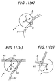
- Fig.11a shows that there is a road R running across the circle A which has its center on the last estimated current car position P. Then, a tentatively presumable current car position is put on the point Q at which the road R and a line from the last estimated current car position P1 extending perpendicular to the road R cross each other.
- Fig.11b shows that there are two roads R1 and R2 running across the circle A which has its center on the last estimated current car position P. Then, tentatively presumable current car positions are put on the point Q1 and Q2 at which the roads R1 and R2 and lines extending from the last estimated current car position P perpendicular to the roads R1 and R2 cross each other.
- Fig.11c shows that there is a road R running across the circle A which has its center on the last estimated current car position P, but not permitting a line to be drawn perpendicular to the road R.
- a tentatively presumable current car position is put on the curve Q3 of the road which is closest to the last estimated car position P.
- the radius of the circle A may be varied proportionally to the running distance after no presumable current car position "x" can be determined with reference to Equation 1.
- the estimated car position is corrected by carrying out a pattern-matching between the road pattern and the trace pattern beginning with the last estimated current car position.
- a presumable current car position or positions are put on the road on which the car is supposed to run or on the branch roads extending from the road; a decision is made as to whether or not a certain relation, representing the possible erroneous locating range, holds between the last estimated current car position and each presumable current car position, and the presumable current car position or positions which were found to satisfy the relation, are selected; a pattern-matching is carried out between the travel trace pattern and each road pattern having the so selected presumable current car position thereon; and finally, the last estimated current car position is shifted to be in registration with the presumable current car position, or one of the presumble current car positions, on the road pattern, thus completing correction of the last estimated current car position.
- the number of roads selected for pattern-matching can be reduced and accordingly the necessary pattern-matchings can be carried out efficiently, and correction of the current car position can be performed more promptly with acceptable accuracy.
Landscapes
- Engineering & Computer Science (AREA)
- Radar, Positioning & Navigation (AREA)
- Remote Sensing (AREA)
- Physics & Mathematics (AREA)
- Theoretical Computer Science (AREA)
- General Physics & Mathematics (AREA)
- Mathematical Physics (AREA)
- Business, Economics & Management (AREA)
- Educational Administration (AREA)
- Educational Technology (AREA)
- Automation & Control Theory (AREA)
- Navigation (AREA)
Abstract
Description
- The present invention relates to an apparatus for displaying a travel path in which the current position of a moving body such as an automobile is given on a road map appearing on a screen.
- In an attempt to prevent a driver from losing his way when travelling in a place in which he is a stranger, an apparatus for displaying a travel path has been proposed in which the current position of the moving body is sequentially estimated in terms of X- and Y-coordinates by carrying out algorithmic operation on the running distance and direction which are determined by an associated distance meter and direction sensor, to show him the current position of his car in the form of a dot on a road map appearing on a screen.
- Accumulation of errors in determining the running distance and direction will cause a wrong indication of the current position of the car. Sometimes, a wrong current car position becomes increasingly separated from all roads appearing on the map until the driver cannot determine on which road his car is running.
- In an attempt to solve this problem it has been proposed that a travel trace,having sequentially renewed estimated current car positions thereon, is compared with all the roads in the vicinity of the last estimated current car position on the screen to find similarity in pattern among these roads according to a conventional pattern matching process and select one,which is closest in shape to the travel trace, as the "true" road on which the car is running, and then the dot image of the last estimated current car position is put on the apparently true road.
- This correction, however, will require much time if many roads and branch roads appear in the vicinity of the last estimated current car position because a pattern matching must be carried out for each of these selected roads.
- With the above in mind one object of the present invention is to provide an apparatus for displaying travel path which permits necessary pattern matching with an increased efficiency and accuracy to find the current position of a car within a minimum possible time.
- Specifically, the invention seeks to provide an apparatus in which the necessary pattern matching is carried out on a reduced number of roads selected for identification.
- To attain this object an apparatus for displaying travel path according to the present invention comprises: first processing means for setting, each time the moving body runs a predetermined running distance in the displayed road map, an estimated current position of the moving body each on a road or roads or their branch roads on which the moving body is supposed to run. with reference to the previously stored X- and Y- coordinates of a road or roads of the road map; second processing means for making, each time the moving body runs the said predetermined running distance, a decision as to whether or not a given correlation is established between a selected presumably current position and the last estimated position of the moving body and, in the affirmative case, selecting a road having the presumably current position thereon; third processing means for carrying out a pattern-matching between the travel trace pattern running to the last estimated current position and the so selected road pattern; and fourth processing means for putting the travel course of the moving body in registration with the selected road of the road map.
- With this arrangement necessary pattern-matching for reducing any offset of the estimated current car position from a road on which the car is supposed to run to find the exact current car position, is effected by setting a presumably current car position, on a road on which the car is supposed to run or its road branches; making a decision as to whether or not a predetermined relation representing the possible erroneous locating range, is established between the estimated current car position and the presumably current car position, and selecting in the affirmative case, the road or road branches each having the presumably current car position; and effecting a pattern matching between the travel trace having sequential estimated current car positions thereon and each of the so selected road or road branches. Thus, a least number of road or road branches are selected for pattern-matching, and accordingly the time involved for pattern-matching can be reduced to possible minimum.
- According to one aspect of the present invention each time the accumulation of directional increments reaches a fixed amount, necessary pattern-matching is effected between the travel trace drawn while directional increments were integrated and a selected road on the road map to make a decision as to whether or not the selected road is the one on which the car is running, thereby improving the efficiency with which the necessary pattern matching is effected to find the correct current car position.
- According to another aspect of the present invention a travel trace having sequential estimated positions thereon and a selected road in the road map are given in the form of broken line composed of straight increments of equal length, and then necessary pattern-matching is effected by comparing each subsequent increment of the selected road approximation with corresponding increment of the travel trace approximation in terms of position and direction, thereby facilitating matching work and improving the accuracy with which pattern-matching is effected.
- According to still another aspect of the present invention a travel trace having sequential estimated positions thereon and a selected road in the road map are given in the form of broken line composed of straight increments of equal length, and then necessary pattern-matching is effected by putting the travel trace approximation parallel with the selected road approximation and then determining correlation between each subsequent increment of the selected road approximation and corresponding increment of the travel trace approximation, facilitating matching work and improving the accuracy with which pattern-matching is effected.
- According to still another aspect of the present invention in case that no presumably current position can be found within a first distance range from the last estimated car position, necessary pattern-matching is effected by setting a tentatively presumable current position on a road or roads running within a second longer distance range; setting sequentially tentatively presumable current positions on the same road or roads until a tentatively presumable current position on such road or one of such roads has come close to enter the first distance range from the last estimated position; and then regarding the tentatively presumable current oisition on such road or one of such roads as the presumable current position, thereby permitting necessary pattern matching to continue without interruption even if estimated car positions are far from roads on the road map.
- For a better understanding of the present invention, and to show how it may be brought into effect, reference will now be made, by way of example, to the accompanying drawings in which:-
- Fig. 1 is a block diagram schematically showing an apparatus for displaying a travel path according to the present invention.
- Fig. 2 shows an image of a road map and a series of dots representing sequential current car positions appearing on the screen of the travel path displaying apparatus;
- Fig. 3 shows a similar road map image, but showing departure of a travel course having sequential current car positions thereon from the road on the road map;
- Figs. 4(a) and 4 (b) show how presumable current car positions are put on a road and road branches for each increment of running distance, respectively;
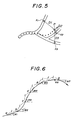
- Fig. 5 shows how the last estimated car position are related with corresponding presumable current car positions on selected roads in the road map;
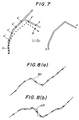
- Fig. 8 shows how subsequent increments change in direction in a travel path;
- Fig. 7 shows how a road pattern is formed, which road pattern is to be "nominated" for pattern-matching;
- Figs. 8(a) and 8(b) show respectively travel trace and selected road approximations given in broken lines each composed of straight increments of equal length;
- Fig. 9 shows how the travel trace and the last estimated car position are put in registration with a selected road, with which the travel path is identified;
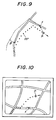
- Fig. 10 shows a road map image errorneously showing that a car is running away from course;
- Figs. 11(a), 11(b) and 11(c) show how presumable current car positions are tentatively put on selected roads, which run across a circle drawn with the last estimated current car position on its center.
- Referring to Fig. 1 there is schematically shown an apparatus for displaying travel path according to the present invention. It comprises an opto-electrical, electromagnetic or mechanical-contact type distance sensor 1 which is responsive for instance, to rotation of the wheels of a car for generating a pulse signal each time the car runs a unit distance; a direction sensor 2 such as a gyroscope which is capable of detecting any variation in angular speed in the yaw direction; a
signal processing unit 3 which is composed of a central processor unit for controlling the whole system, ROMs for storing programs and RAMs for storing controlling data, the signal processing unit being capable of counting the pulses from the distance sensor 1 to determine the running distance of the car, determining the direction in which the car is running on the basis of the signals from the direction sensor 2, and conduct ing accumulative algorithmic operation of vectors to determine the current car position in terms of X- and Y- coordinates for each unit running distance; a travel trace storing unit (RAM) 4 for sequentially storing the X- and y- coordinates of current car positions; a roadmap storage medium 5 storing different road maps in a file; a storagemedium reader unit 8 for selectively reading different road maps in a file; adisplay unit 7 for presenting a selected road map and the travel trace in terms of sequential current car positions and directions on an associated screen; amanual operating unit 8 for sending commands for operation, selecting a desired road map from the file, setting a starting position at a given point on the selected road map, turning the selected road map or turning the travel trace on the selected map, shifting selected dots representing car positions on the road map, enlarging or reducing selected areas in the road map at a desired rate and performing other required operations. - In operation a selected road map appears on the screen of the
display unit 7, and current car positions are given sequentially in dots on a selected road in the screen to indicate a travel trace which the car has already run while thesignal processing unit 3 is carrying out necessary algorithmic operations to renew the X- and Y coordinates of current car position in the travel trace storing unit (RAM) 4. Thus, as seen in Fig. 2, the screen of thedisplay unit 7 shows the last estimated current car position M₁, the direction M₂ in which the car is about to run from the last estimated current car position, and sequential car positions M₃ plotted one after another from the starting position S. - The arrangement and operation described so far are the same as the conventional travel path displaying apparatus described above .
- In the conventional travel path displaying apparatus, positioning errors are apt to be accumulated as a car runs a relatively long distance, and accordingly the travel trace deviates increasingly far from a selected road in the road map until the car cannot be located on the road map (as shown in Figure 3).
- Such travel path displaying apparatus is improved according to the present invention in that the travel trace having sequential and last estimated current car positions thereon, is corrected and put in registration with the true road by selecting a road or roads in the vicinity of the last estimated current car position and conducting pattern-matching between the travel trace and each of the so selected roads. Specifically, the number of selected roads with respect to which the travel trace is to be checked for similarity, is reduced to a minimum, but is still adequate to permit the selection of the true road and exact location of the car in the road map, thus reducing the burden of pattern-matching in the central processor unit to the minimum possible.
- Referring to Fig. 4 (a), if the car is running on a straight road having no branches within a predetermined distance L from the last presumable current car position x′, the subsequent presumable current car position x is set the predetermined distance L ahead from the last presumable current car position x′ on the same road. Referring to Fig. 4 (b), if the car is running on a straight road having branches within a predetermined distance L from the last presumable current car position x′, the subsequent presumable current car positions x1, x2, and x3 are set the predetermined distance L ahead from the last presumable current car position x′ on all the branches (1₁ +1₂= =1₁ +1₃ =1₁+1₄=L).
- Each time the distance measuring unit 1 detects that the car has run a given constant distance L, the
signal processor 3 carries out the necessary algorithmic operation with reference to the coordinates of the position of the selected road appearing on the screen of thedisplay unit 7 to automatically put presumable current car positions on the roads. Presumable current car positions may be sequentially renewed after a predetermined time rather than a predetermined distance. - Also, the interval between subsequent settings of presumable current car positions may be varied depending on the traffic condition of the road. The X- and Y- coordinates of each road are stored in the road
map memory medium 5. - Next, a decision is made as to whether or not the distance between each of the presumable current car positions and the last estimated current car position which may deviate from all the roads, is within a given tolerance and a road or roads having the presumable current car positions within such tolerance are selected, and only the road or roads thus selected will be subjected to pattern-matching.
- Referring to Fig. 5, the distances between presumable current car positions x (x₁, x₂ and x₃) and the estimated current car position P are indicated at D (D₁, D₂ and D₃).
- Presumable current car positions which meet the following equation (1), are selected.
D ≦ αL + M (1)
where "M" stands for a predetermined allowance, for instance 50 metres "α" stands for a coefficient relating to the accuracy with which the car is located with reference to running distance as a parameter, forinstance 5%, and "L" is set, for instance, at 100 metres. - Alternatively, presumable current car positions which are found on roads extending within a predetermined angular tolerance when measured with respect to the direction in which the car is about to move from the last estimated current car position, may be selected to determine which roads are nominated for pattern-matching.
- For a relatively small value of "M" only the presumable current car position x₂ may be selected, and then the road on which the presumable current car position x₂ is found will be "nominated" for pattern matching.
- Thus, if there are many roads in the vicinity of the last estimated current car position,a reduced number of most probable true roads will be selected for pattern matching, thereby minimizing the burden of pattern matching process.
- In a travel path displaying apparatus according to the present invention the direction of a car is constantly monitored, and each time the integration of angular variations increases above a predetermined amount, the travel trace is presumed to change in shape, and then a necessary pattern matching is carried out. Apparently, this will substantially reduce the burden of pattern matching, compared with that which would be required if a pattern matching were carried out each time a presumable current car position is set after running a predetermined distance.
- Specifically, as seen from Fig. 6, an angular direction w₁ (i=1,2,3,...) is determined at points a,b,c,d,..., predetermined distances apart from each other, an angular variation is determined on the basis of the angular direction and the previously determined angular direction, and the accumulation W of these angular variations is calculated from the following equation:

- When the angular accumulation W increases above a predetermined value, the travel trace running from the start point "a" (at which the last pattern matching was carried out) to the last estimated current car position is selected and "nominated" for pattern matching.
- Thus, a travel trace having a noticeable change in shape is selected for pattern-matching. Therefore, the accuracy with which the pattern matching is carried out, will be substantially improved, and in addition, the number of times pattern-matching is necessary will be substantially reduced. As seen from Fig. 7, a road pattern to be "nominated" for pattern-matching is the one having presumable current car positions x′ thereon with the presumable current position x corresponding to the last estimated current car position P at its head and with the point S at which the last pattern-matching was carried out at its tail.
- In forming a road pattern having presumable current car positions thereon for the purpose of carrying out pattern-matching efficiently, it is necessary to increase the value of M in the equation (1) at a given fixed rate with the increase of the travelling distance of the car because the distance between an estimated current car position and a corresponding presumable car position will increase with the increase of the travelling distance of the car.
- Also, in carrying out a necessary pattern-matching between a trace pattern RP and a "nominated" road pattern KP, as shown in Figures 8(a) and 8(b) respectively, the
signal processing unit 3 works on these patterns to convert them into approximations of broken line of equal length, and then a pattern matching is carried out between each of subsequent vectors in the trace and road pattern approximations. This divisional pattern-matching can be carried out by comparing each vector with a corresponding one in direction and position, and it can be carried out with ease and accuracy. - Specifically, a positional correlation is determined between the trace pattern and the road pattern by first, rotating the trace pattern until it is put in parallel relation with the road pattern, and then, summing the distances between individual vectors of the trace and road pattern approximations as follows:
- First, the rotating angle ϑ of a series of vectors (s₁,s₂, s₃...,sn) of the trace pattern with respect to a series of vectors (r₁,r₂,r₃...,rn) of the road pattern is determined by:

- Second, the series of trace vectors is rotated by ϑ by using the following equation:

- The rotation of the trace vectors reduction of directional errors, if any.
- Third, the value "f" of the positional correlation between the trace and road vector series is determined by:

- Finally, the smallest value is selected from these correlation values f, and if the smallest value thus selected is found to be below a given reference value, it is decided that these patterns are mated. Then, the trace pattern RP is so translated that the last current car position P may be put on the top position of the road pattern (for instance x+δ position), and then the trace pattern RP is rotated by ϑ so that it may be put in registration with the road pattern , as shown in Figure 9.
- The pattern-matching process thus described permits correction of the position of a car if its estimated position is determined as separated from every road appearing on a road map.
- The extending or shortening distance from the last estimated current position x on the nominated road is divided into a plurality of segments, and then the plurality of road patterns having extending or shortening sections at their top positions, are formed. Then, the correlation value f is determined between each road pattern and the trace pattern. When the smallest correlation value f is found to be below a reference value, a decision of establishment of pattern-matching is made. This process improves the accuracy with which pattern-matching is effected.
- In selectively nominating a road for pattern-matching with reference to the last estimated current car position x as described earlier: if the car deviates from all roads in the road map as shown in Fig. 10, and if the estimated current car position P is too far from the roads to apply Equation 1 in determinning which road the corresponding presumable current position x is to be put, then no road can be nominated for pattern-matching, and therefore pattern-matching will be impossible.
- In an attempt to carry out necessary pattern-matchings without interruption even if the car deviates too far from all roads to determine which road a presumable current car position is to be put on, a search is made for a road or roads running across a circle having a predetermined radius (for instance, 100 meters) with its centre at the last estimated current car position, and, if such road or roads are found, a tentatively presumable current car position or positions are set on the road or roads at the point or points which are closest to the last estimated current car position. The tentatively presumable current car position or positions are renewed each time the car runs a predetermined distance until they come close enough to the last estimated current car position to permit application of Equation 1, and then the last tentatively presumable current car position or positions are regarded as equivalent to the real presumable current car position or positions. Thus, necessary pattern-matching can be effected . In practice, while the car is deviating from all roads in the road map, the image of the travel trace is not given on the screen, and after the presumable current car position is set on the selected road, necessary pattern-matchings are carried out between the selected road patterns and the travel trace pattern.
- As for a decision as to whether or not there is a road within a fixed distance range from the last estimated current car position, it may be made without interruption Otherwise, such decision may be made at intervals, for instance at every occurrence of a timing pulse or each time the car runs a predetermined distance (for instance 100 meters).
- Fig.11a shows that there is a road R running across the circle A which has its center on the last estimated current car position P. Then, a tentatively presumable current car position is put on the point Q at which the road R and a line from the last estimated current car position P1 extending perpendicular to the road R cross each other.
- Fig.11b shows that there are two roads R1 and R2 running across the circle A which has its center on the last estimated current car position P. Then, tentatively presumable current car positions are put on the point Q1 and Q2 at which the roads R1 and R2 and lines extending from the last estimated current car position P perpendicular to the roads R1 and R2 cross each other.
- Fig.11c shows that there is a road R running across the circle A which has its center on the last estimated current car position P, but not permitting a line to be drawn perpendicular to the road R. In this case a tentatively presumable current car position is put on the curve Q3 of the road which is closest to the last estimated car position P.
- In order to reduce the time involved for catching the sight of a road within the circle despite the increasing erroneous estimation of current car position P, the radius of the circle A may be varied proportionally to the running distance after no presumable current car position "x" can be determined with reference to Equation 1.
- As is apparent from the above, in the case that the car position, if indicated on the screen, would deviate from the road on which the car is supposed to run as a result of accumulation of errors in estimating the current car position, the estimated car position is corrected by carrying out a pattern-matching between the road pattern and the trace pattern beginning with the last estimated current car position. Then, a presumable current car position or positions are put on the road on which the car is supposed to run or on the branch roads extending from the road; a decision is made as to whether or not a certain relation, representing the possible erroneous locating range, holds between the last estimated current car position and each presumable current car position, and the presumable current car position or positions which were found to satisfy the relation, are selected; a pattern-matching is carried out between the travel trace pattern and each road pattern having the so selected presumable current car position thereon; and finally, the last estimated current car position is shifted to be in registration with the presumable current car position, or one of the presumble current car positions, on the road pattern, thus completing correction of the last estimated current car position. According to this invent ion the number of roads selected for pattern-matching can be reduced and accordingly the necessary pattern-matchings can be carried out efficiently, and correction of the current car position can be performed more promptly with acceptable accuracy.
Claims (12)
means for successively estimating coordinates of a current position of a moving body;
means for storing data relating to the successively estimated current positions of the moving body and data relating to the coordinates of roads along which the body may move;
display means for showing successively determined and/or estimated current positions of the moving body on a map including the roads; and
processing means, characterised in that the processing means is adapted such that:
at predetermined intervals a presumable current position is calculated for the body with respect to one or more road, whose position differs from the previously determined position of the moving body by a distance corresponding to the distance which the moving body is estimated to have travelled during the preceding predetermined interval;
for each presumable current position, a check is made as to whether a given relationship between the presumable current position and the current estimated position is satisfied, and the or each presumable current position for which the relationship is satisfied is selected;
for each selected presumable current position, a road pattern leading to the selected presumable current position from the previously determined current position is compared with a pattern of successive estimated positions from the previously determined current position to the current estimated position; and
one such selected presumable current position is determined, on the basis of such comparison, to be the current position of the moving body.
first processing means for setting, each time the moving body runs a predetermined running distance, a presumable current position corresponding to an estimated current position of the moving body each on a roads, or their branch roads on which the moving body is supposed to run, with reference to the previously stored X- and Y- coordinates of a road or roads of the road map;
second processing means for making each time the moving body runs the said predetermined running distance, a decision as to whether or not a given correlation is established between a selected presumable current position and the last estimated current position of the moving body, in the affirmative case, selecting a road having presumable current position thereon;
third processing means for carrying out a pattern-matching between the so selected road pattern and the travel trace pattern running to the last estimated current position retrieved from said memory; and
fourth processing means for putting the travel course of the moving body in registration with the selected road of the road map.
Applications Claiming Priority (10)
| Application Number | Priority Date | Filing Date | Title |
|---|---|---|---|
| JP198631/87 | 1987-08-07 | ||
| JP62198633A JPH061196B2 (en) | 1987-08-07 | 1987-08-07 | Driving route display device |
| JP198630/87 | 1987-08-07 | ||
| JP62198631A JPH0711424B2 (en) | 1987-08-07 | 1987-08-07 | Driving route display device |
| JP19863087A JPH0629736B2 (en) | 1987-08-07 | 1987-08-07 | Driving route display device |
| JP198632/87 | 1987-08-07 | ||
| JP62198632A JPH0711425B2 (en) | 1987-08-07 | 1987-08-07 | Driving route display device |
| JP62198634A JPH0711426B2 (en) | 1987-08-07 | 1987-08-07 | Driving route display device |
| JP198634/87 | 1987-08-07 | ||
| JP198633/87 | 1987-08-07 |
Publications (2)
| Publication Number | Publication Date |
|---|---|
| EP0302736A1 true EP0302736A1 (en) | 1989-02-08 |
| EP0302736B1 EP0302736B1 (en) | 1992-06-03 |
Family
ID=27529190
Family Applications (1)
| Application Number | Title | Priority Date | Filing Date |
|---|---|---|---|
| EP88307240A Expired EP0302736B1 (en) | 1987-08-07 | 1988-08-05 | Apparatus for displaying travel path |
Country Status (4)
| Country | Link |
|---|---|
| US (1) | US4963864A (en) |
| EP (1) | EP0302736B1 (en) |
| CA (1) | CA1326273C (en) |
| DE (1) | DE3871644T2 (en) |
Cited By (10)
| Publication number | Priority date | Publication date | Assignee | Title |
|---|---|---|---|---|
| EP0346906A2 (en) * | 1988-06-16 | 1989-12-20 | Nissan Motor Co., Ltd. | System for displaying the present position of a moving object |
| EP0391647A2 (en) * | 1989-04-07 | 1990-10-10 | Sumitomo Electric Industries, Ltd. | Calibration apparatus of angular velocity sensor in self-contained navigational system |
| DE4033668A1 (en) * | 1989-10-24 | 1991-04-25 | Mitsubishi Electric Corp | Navigation system e.g. for motor vehicle - is switchable between modes displaying map, instantaneous and stored positions and map and instantaneous position only |
| EP0514887A2 (en) * | 1991-05-21 | 1992-11-25 | Matsushita Electric Industrial Co., Ltd. | Vehicle position detecting apparatus |
| EP0593256A1 (en) * | 1992-10-14 | 1994-04-20 | Pioneer Electronic Corporation | Navigation apparatus |
| EP0747669A2 (en) * | 1995-06-09 | 1996-12-11 | Xanavi Informatics Corporation | Current position calculating device |
| EP0747668A2 (en) * | 1995-06-09 | 1996-12-11 | Xanavi Informatics Corporation | Current position calculating system for a vehicle having a function for correcting a vehicle direction |
| WO2003027611A2 (en) * | 2001-09-19 | 2003-04-03 | Robert Bosch Gmbh | Method for determining and storing supplementary digitised route information and corresponding navigation system |
| CN102313556A (en) * | 2010-07-01 | 2012-01-11 | 北京四维图新科技股份有限公司 | Method and device for matching paths on round island |
| EP2862735A1 (en) * | 2000-03-27 | 2015-04-22 | Bose Corporation | Method for improving accuracy of vehicle position determination |
Families Citing this family (26)
| Publication number | Priority date | Publication date | Assignee | Title |
|---|---|---|---|---|
| US5170165A (en) * | 1987-08-07 | 1992-12-08 | Honda Giken Kogyo Kabushiki Kaisha | Apparatus for displaying travel path |
| US5243528A (en) * | 1990-09-12 | 1993-09-07 | Motorola, Inc. | Land vehicle navigation apparatus with visual display |
| US5416477A (en) * | 1990-11-06 | 1995-05-16 | Matsushita Electric Industrial Co., Ltd. | Navigation system mounted on vehicle |
| JP2657581B2 (en) * | 1990-11-28 | 1997-09-24 | 本田技研工業株式会社 | Current position display device of moving object |
| DE69217311T2 (en) * | 1991-09-25 | 1997-07-24 | Philips Electronics Nv | Device and method for map display in vehicle navigation |
| US5544060A (en) * | 1991-10-16 | 1996-08-06 | Zexel Usa Corporation | Vehicle mounted navigation system with preview function |
| US5473324A (en) * | 1992-12-28 | 1995-12-05 | Matsushita Electric Industrial Co., Ltd. | Map display apparatus |
| DE4332945A1 (en) * | 1993-09-28 | 1995-03-30 | Bosch Gmbh Robert | Positioning and navigation device with satellite support |
| JP3359738B2 (en) * | 1994-05-13 | 2002-12-24 | パイオニア株式会社 | Target location information provision method |
| EP0740281B1 (en) * | 1994-11-14 | 1999-09-29 | Xanavi Informatics Corporation | Map display device for vehicle |
| US5682525A (en) | 1995-01-11 | 1997-10-28 | Civix Corporation | System and methods for remotely accessing a selected group of items of interest from a database |
| JP3781795B2 (en) * | 1995-01-20 | 2006-05-31 | 三菱電機株式会社 | Mobile navigation device |
| JP3351650B2 (en) * | 1995-03-28 | 2002-12-03 | アルパイン株式会社 | Demonstration method of navigation device |
| US6127945A (en) * | 1995-10-18 | 2000-10-03 | Trimble Navigation Limited | Mobile personal navigator |
| US6024655A (en) * | 1997-03-31 | 2000-02-15 | Leading Edge Technologies, Inc. | Map-matching golf navigation system |
| US20040215387A1 (en) * | 2002-02-14 | 2004-10-28 | Matsushita Electric Industrial Co., Ltd. | Method for transmitting location information on a digital map, apparatus for implementing the method, and traffic information provision/reception system |
| JP3481168B2 (en) * | 1999-08-27 | 2003-12-22 | 松下電器産業株式会社 | Digital map location information transmission method |
| JP5041638B2 (en) * | 2000-12-08 | 2012-10-03 | パナソニック株式会社 | Method for transmitting location information of digital map and device used therefor |
| JP4663136B2 (en) * | 2001-01-29 | 2011-03-30 | パナソニック株式会社 | Method and apparatus for transmitting location information of digital map |
| JP4749594B2 (en) | 2001-04-27 | 2011-08-17 | パナソニック株式会社 | Digital map location information transmission method |
| JP4230132B2 (en) * | 2001-05-01 | 2009-02-25 | パナソニック株式会社 | Digital map shape vector encoding method, position information transmission method, and apparatus for implementing the same |
| US6560531B1 (en) * | 2001-05-22 | 2003-05-06 | Navigation Technologies Corporation | Multi-resolution trend metric for shape comparison and applications thereof |
| WO2008036325A2 (en) * | 2006-09-20 | 2008-03-27 | Regents Of The University Of Minnesota | Indoor navigation system and method |
| JP7389541B2 (en) * | 2017-08-10 | 2023-11-30 | いすゞ自動車株式会社 | Traffic management device, traffic management method, and traffic management system |
| SE542743C2 (en) * | 2018-11-06 | 2020-07-07 | Mobilaris Mce Ab | Method and device for determining the position of a moving object |
| US11927449B2 (en) * | 2019-06-10 | 2024-03-12 | Nvidia Corporation | Using map-based constraints for determining vehicle state |
Citations (2)
| Publication number | Priority date | Publication date | Assignee | Title |
|---|---|---|---|---|
| EP0036119A1 (en) * | 1980-03-06 | 1981-09-23 | Patrice Bernard | Vehicle localisation system |
| GB2174497A (en) * | 1985-04-19 | 1986-11-05 | Honda Motor Co Ltd | Apparatus for displaying travel path |
Family Cites Families (9)
| Publication number | Priority date | Publication date | Assignee | Title |
|---|---|---|---|---|
| JPS5725764A (en) * | 1980-07-22 | 1982-02-10 | Nec Corp | Guard monitor device |
| JPS5939800B2 (en) * | 1980-10-27 | 1984-09-26 | 本田技研工業株式会社 | Fixed distance display method in driving route display device |
| JPS60202307A (en) * | 1984-03-28 | 1985-10-12 | Hitachi Ltd | Navigation system having advance instructing function |
| JPS60229799A (en) * | 1984-04-27 | 1985-11-15 | 三菱電機株式会社 | Navigator for car |
| JPH0644184B2 (en) * | 1985-03-11 | 1994-06-08 | 日産自動車株式会社 | Vehicle route guidance device |
| JPS61209316A (en) * | 1985-03-14 | 1986-09-17 | Nissan Motor Co Ltd | Route guide apparatus for vehicle |
| JP2526876B2 (en) * | 1986-11-17 | 1996-08-21 | 日本電装株式会社 | Vehicle traveling position display device |
| US4807127A (en) * | 1986-12-10 | 1989-02-21 | Sumitomo Electric Industries, Ltd. | Vehicle location detecting system |
| JP2753882B2 (en) * | 1990-04-20 | 1998-05-20 | 富士写真フイルム株式会社 | Magnetic recording medium and method of manufacturing the same |
-
1988
- 1988-07-25 CA CA000572942A patent/CA1326273C/en not_active Expired - Lifetime
- 1988-07-27 US US07/224,985 patent/US4963864A/en not_active Expired - Lifetime
- 1988-08-05 EP EP88307240A patent/EP0302736B1/en not_active Expired
- 1988-08-05 DE DE8888307240T patent/DE3871644T2/en not_active Expired - Lifetime
Patent Citations (2)
| Publication number | Priority date | Publication date | Assignee | Title |
|---|---|---|---|---|
| EP0036119A1 (en) * | 1980-03-06 | 1981-09-23 | Patrice Bernard | Vehicle localisation system |
| GB2174497A (en) * | 1985-04-19 | 1986-11-05 | Honda Motor Co Ltd | Apparatus for displaying travel path |
Non-Patent Citations (1)
| Title |
|---|
| PROCEEDINGS OF THE 1985 INTERNATIONAL CONFERENCE ON INDUSTRIAL ELECTRONICS, CONTROL AND INSTRUMENTATION, San Francisco, California, 18th-22nd November 1985, vol. 1, pages 170-173, IEEE, New York, US; S.K. HONEY et al.: "A novel approach to automotive navigation and map display" * |
Cited By (22)
| Publication number | Priority date | Publication date | Assignee | Title |
|---|---|---|---|---|
| EP0346906A2 (en) * | 1988-06-16 | 1989-12-20 | Nissan Motor Co., Ltd. | System for displaying the present position of a moving object |
| EP0346906A3 (en) * | 1988-06-16 | 1991-05-29 | Nissan Motor Co., Ltd. | System for displaying the present position of a moving object |
| EP0391647A2 (en) * | 1989-04-07 | 1990-10-10 | Sumitomo Electric Industries, Ltd. | Calibration apparatus of angular velocity sensor in self-contained navigational system |
| EP0391647A3 (en) * | 1989-04-07 | 1992-02-05 | Sumitomo Electric Industries, Ltd. | Calibration apparatus of angular velocity sensor in self-contained navigational system |
| EP0602013A2 (en) * | 1989-04-07 | 1994-06-15 | Sumitomo Electric Industries, Ltd | Calibration apparatus of angular velocity sensor in self-contained navigational system |
| EP0602013A3 (en) * | 1989-04-07 | 1994-08-17 | Sumitomo Electric Industries | Calibration apparatus of angular velocity sensor in self-contained navigational system. |
| DE4033668A1 (en) * | 1989-10-24 | 1991-04-25 | Mitsubishi Electric Corp | Navigation system e.g. for motor vehicle - is switchable between modes displaying map, instantaneous and stored positions and map and instantaneous position only |
| EP0514887A2 (en) * | 1991-05-21 | 1992-11-25 | Matsushita Electric Industrial Co., Ltd. | Vehicle position detecting apparatus |
| EP0514887A3 (en) * | 1991-05-21 | 1993-09-08 | Matsushita Electric Industrial Co., Ltd. | Vehicle position detecting apparatus |
| EP0593256A1 (en) * | 1992-10-14 | 1994-04-20 | Pioneer Electronic Corporation | Navigation apparatus |
| EP0747669A2 (en) * | 1995-06-09 | 1996-12-11 | Xanavi Informatics Corporation | Current position calculating device |
| EP0747668A2 (en) * | 1995-06-09 | 1996-12-11 | Xanavi Informatics Corporation | Current position calculating system for a vehicle having a function for correcting a vehicle direction |
| EP0747669A3 (en) * | 1995-06-09 | 1998-02-25 | Xanavi Informatics Corporation | Current position calculating device |
| EP0747668A3 (en) * | 1995-06-09 | 1998-02-25 | Xanavi Informatics Corporation | Current position calculating system for a vehicle having a function for correcting a vehicle direction |
| US5839087A (en) * | 1995-06-09 | 1998-11-17 | Zanavy Informatics Kk | Current position calculating system for a vehicle having a function for correcting a vehicle direction |
| US5941934A (en) * | 1995-06-09 | 1999-08-24 | Xanavi Informatics Corporation | Current position calculating device |
| EP1288623A1 (en) * | 1995-06-09 | 2003-03-05 | Xanavi Informatics Corporation | Current position calculating device |
| EP2862735A1 (en) * | 2000-03-27 | 2015-04-22 | Bose Corporation | Method for improving accuracy of vehicle position determination |
| WO2003027611A2 (en) * | 2001-09-19 | 2003-04-03 | Robert Bosch Gmbh | Method for determining and storing supplementary digitised route information and corresponding navigation system |
| WO2003027611A3 (en) * | 2001-09-19 | 2003-08-07 | Bosch Gmbh Robert | Method for determining and storing supplementary digitised route information and corresponding navigation system |
| CN102313556A (en) * | 2010-07-01 | 2012-01-11 | 北京四维图新科技股份有限公司 | Method and device for matching paths on round island |
| CN102313556B (en) * | 2010-07-01 | 2014-04-02 | 北京四维图新科技股份有限公司 | Method and device for matching paths on round island |
Also Published As
| Publication number | Publication date |
|---|---|
| US4963864A (en) | 1990-10-16 |
| EP0302736B1 (en) | 1992-06-03 |
| CA1326273C (en) | 1994-01-18 |
| DE3871644D1 (en) | 1992-07-09 |
| DE3871644T2 (en) | 1993-02-04 |
Similar Documents
| Publication | Publication Date | Title |
|---|---|---|
| EP0302736B1 (en) | Apparatus for displaying travel path | |
| US5170165A (en) | Apparatus for displaying travel path | |
| EP0487864B1 (en) | Apparatus for displaying a travel position | |
| EP0166547B1 (en) | Vehicle navigational apparatus | |
| US5689423A (en) | Vehicle navigation system for evaluating a return route based on cost | |
| US5922036A (en) | Lane detection sensor and navigation system employing the same | |
| US5016007A (en) | Apparatus for displaying travel path | |
| EP0272077B1 (en) | Apparatus for displaying travel path | |
| US5003306A (en) | Apparatus for displaying current location | |
| JPH061196B2 (en) | Driving route display device | |
| JP2811520B2 (en) | How to correct the position of vehicle navigation | |
| US6236935B1 (en) | Navigation-assistance method and device for a vehicle driver | |
| JPH0629736B2 (en) | Driving route display device | |
| JPH07109366B2 (en) | Current position display of mobile | |
| JPH0670568B2 (en) | Driving route display device | |
| JP2657549B2 (en) | Current position display device of moving object | |
| JPH07113999B2 (en) | Vehicle location recognition method | |
| JP3551473B2 (en) | Vehicle travel position estimation device | |
| JP3758710B2 (en) | Current position calculation system and current position calculation method | |
| JP2709635B2 (en) | Current position display device of moving object | |
| JPH0711426B2 (en) | Driving route display device | |
| JPH04345190A (en) | Navigation device | |
| JPH0711424B2 (en) | Driving route display device | |
| JPH0326914A (en) | Display apparatus of current position of moving body | |
| JPH0758201B2 (en) | Current position display of mobile |
Legal Events
| Date | Code | Title | Description |
|---|---|---|---|
| PUAI | Public reference made under article 153(3) epc to a published international application that has entered the european phase |
Free format text: ORIGINAL CODE: 0009012 |
|
| AK | Designated contracting states |
Kind code of ref document: A1 Designated state(s): DE FR GB |
|
| 17P | Request for examination filed |
Effective date: 19890131 |
|
| 17Q | First examination report despatched |
Effective date: 19910118 |
|
| GRAA | (expected) grant |
Free format text: ORIGINAL CODE: 0009210 |
|
| AK | Designated contracting states |
Kind code of ref document: B1 Designated state(s): DE FR GB |
|
| REF | Corresponds to: |
Ref document number: 3871644 Country of ref document: DE Date of ref document: 19920709 |
|
| ET | Fr: translation filed | ||
| ET1 | Fr: translation filed ** revision of the translation of the patent or the claims | ||
| PLBE | No opposition filed within time limit |
Free format text: ORIGINAL CODE: 0009261 |
|
| STAA | Information on the status of an ep patent application or granted ep patent |
Free format text: STATUS: NO OPPOSITION FILED WITHIN TIME LIMIT |
|
| 26N | No opposition filed | ||
| REG | Reference to a national code |
Ref country code: GB Ref legal event code: IF02 |
|
| PGFP | Annual fee paid to national office [announced via postgrant information from national office to epo] |
Ref country code: DE Payment date: 20070802 Year of fee payment: 20 |
|
| PGFP | Annual fee paid to national office [announced via postgrant information from national office to epo] |
Ref country code: GB Payment date: 20070801 Year of fee payment: 20 |
|
| PGFP | Annual fee paid to national office [announced via postgrant information from national office to epo] |
Ref country code: FR Payment date: 20070808 Year of fee payment: 20 |
|
| REG | Reference to a national code |
Ref country code: GB Ref legal event code: PE20 Expiry date: 20080804 |
|
| PG25 | Lapsed in a contracting state [announced via postgrant information from national office to epo] |
Ref country code: GB Free format text: LAPSE BECAUSE OF EXPIRATION OF PROTECTION Effective date: 20080804 |