EP0302707B1 - Method and equipment for accurately positioning items in shafts or piles - Google Patents
Method and equipment for accurately positioning items in shafts or piles Download PDFInfo
- Publication number
- EP0302707B1 EP0302707B1 EP19880307140 EP88307140A EP0302707B1 EP 0302707 B1 EP0302707 B1 EP 0302707B1 EP 19880307140 EP19880307140 EP 19880307140 EP 88307140 A EP88307140 A EP 88307140A EP 0302707 B1 EP0302707 B1 EP 0302707B1
- Authority
- EP
- European Patent Office
- Prior art keywords
- frame
- locating
- pair
- borehole
- guide frames
- Prior art date
- Legal status (The legal status is an assumption and is not a legal conclusion. Google has not performed a legal analysis and makes no representation as to the accuracy of the status listed.)
- Expired
Links
- 238000000034 method Methods 0.000 title claims description 20
- 229910000831 Steel Inorganic materials 0.000 description 19
- 239000010959 steel Substances 0.000 description 19
- 239000004567 concrete Substances 0.000 description 16
- 238000010276 construction Methods 0.000 description 9
- 229910000278 bentonite Inorganic materials 0.000 description 3
- 239000000440 bentonite Substances 0.000 description 3
- SVPXDRXYRYOSEX-UHFFFAOYSA-N bentoquatam Chemical compound O.O=[Si]=O.O=[Al]O[Al]=O SVPXDRXYRYOSEX-UHFFFAOYSA-N 0.000 description 3
- XLYOFNOQVPJJNP-UHFFFAOYSA-N water Substances O XLYOFNOQVPJJNP-UHFFFAOYSA-N 0.000 description 3
- 238000003780 insertion Methods 0.000 description 2
- 230000037431 insertion Effects 0.000 description 2
- 239000011150 reinforced concrete Substances 0.000 description 2
- 239000000725 suspension Substances 0.000 description 2
- 238000012790 confirmation Methods 0.000 description 1
- 238000009434 installation Methods 0.000 description 1
- 238000012423 maintenance Methods 0.000 description 1
- 239000000463 material Substances 0.000 description 1
- 238000012986 modification Methods 0.000 description 1
- 230000004048 modification Effects 0.000 description 1
- 239000004033 plastic Substances 0.000 description 1
- 239000002990 reinforced plastic Substances 0.000 description 1
- 239000004576 sand Substances 0.000 description 1
Images



Classifications
-
- E—FIXED CONSTRUCTIONS
- E02—HYDRAULIC ENGINEERING; FOUNDATIONS; SOIL SHIFTING
- E02D—FOUNDATIONS; EXCAVATIONS; EMBANKMENTS; UNDERGROUND OR UNDERWATER STRUCTURES
- E02D27/00—Foundations as substructures
- E02D27/32—Foundations for special purposes
- E02D27/42—Foundations for poles, masts or chimneys
-
- E—FIXED CONSTRUCTIONS
- E02—HYDRAULIC ENGINEERING; FOUNDATIONS; SOIL SHIFTING
- E02D—FOUNDATIONS; EXCAVATIONS; EMBANKMENTS; UNDERGROUND OR UNDERWATER STRUCTURES
- E02D13/00—Accessories for placing or removing piles or bulkheads, e.g. noise attenuating chambers
- E02D13/04—Guide devices; Guide frames
Definitions
- an item such as a uniform straight column to be located within a shaft, pile or caisson.
- the item is often a steel section or stanchion and can, for example, be a universal column. It can be of any cross-section. It can be made of steel, as mentioned above but can also be of reinforced concrete or plastic, or a combination of one or more of these.
- the steel column may be used to support loads from a structure to be built above the pile.
- the steel column may also be used to support horizontal beams and/or concrete slabs which may be constructed to prop the walls of a basement construction. This type of construction is known as ′top-down′ construction and has time saving advantages to building contractors.
- the steel column is supported at or near ground level on a knife-edge arrangement, and the lower end is embedded in the concrete.
- Still another method is to survey the (generally temporary) casing or shaft bore and to then fix distance pieces to the column such that these distance pieces account for the inaccuracies in positioning the casing or shaft bore, and thereafter to insert the steel column.
- the above methods suffer from one or more of the following drawbacks: excessive time required to install the column; uncertainty of its initial positioning; uncertainty of maintaining the column in position while the concrete sets; the requirement generally for long casings (steel or concrete) which often are difficult or impossible to recover; and additional difficulties if the bore is flooded with water or bentonite suspension.
- the present invention provides a method of accurately locating an elongate element in a desired position in a borehole, which comprises (a) placing into the lined borehole a locating frame having at its upper end a first pair of adjustable guide frames and having at its lower end a second pair of adjustable guide frames; (b) adjusting the first pair of adjustable guide frames to define an entry point for the element which is to be located in the borehole; (c) adjusting the second pair of adjustable guide frames to define a locus for receiving said element; and (d) lowering the element through said first pair and said second pair of guide frames to achieve the desired accurate location of the elongate element.
- At least the upper part of the borehole is lined with a shaft lining tube before the locating frame is put into place.
- a locating frame for use in locating an element in a borehole, which frame comprises (i) a space frame of rectangular cross-section substantially free throughout its interior (axial) space; and (ii) at each end of said space frame, a pair of adjustable guide frames spaced apart axially from one another and each comprising a movable bar parallel to one side of the space frame and in a radial plane, and drive means for moving said movable bar across the interior of the space frame, the respective movable bars of the two adjustable guide frames being oriented mutually orthogonally.
- each adjustable guide frame is part of a movable, planar rectangular unit which can be moved by the drive means from a first position adjacent to one side of the space frame to a second position adjacent the opposite side of the space frame.
- a modification can also be envisaged in which there is just a single guide frame unit carrying orthogonally oriented adjustment bars with their respective drive means.
- a locating frame in accordance with this invention may have a further adjustable guide frame or pair of such guide frames at the opposite end (top end) of the frame; this is not essential, however, since a separate but analogously functioning unit can be fitted over the top of the locating frame to define an entry point for the element which is to be located within the borehole.
- this system can be used to place the column at any desired inclination.
- the system can be used to place items such as steel columns and also other items, possibly of different steel sections, but also of concrete (either reinforced or not) or of plastic, or a combination of one or more of these.
- This type of frame can also be used to place similar items into other types of pile, for example into piles of the continuous flight auger type.
- the frame is generally used above ground, and is accurately located in plan by the use of a heavy base (either of steel or concrete, or a combination) or by means of separate piles (which may be works piles or supernumary piles).
- the means of obtaining correct orientation is similar to that already described, as is the means of adjusting the frame to obtain the correct plan position and inclination of the steel column or similar.
Landscapes
- Engineering & Computer Science (AREA)
- Life Sciences & Earth Sciences (AREA)
- General Life Sciences & Earth Sciences (AREA)
- Mining & Mineral Resources (AREA)
- Paleontology (AREA)
- Civil Engineering (AREA)
- General Engineering & Computer Science (AREA)
- Structural Engineering (AREA)
- Placing Or Removing Of Piles Or Sheet Piles, Or Accessories Thereof (AREA)
Description
- On certain types of constructions there is a requirement for an item such as a uniform straight column to be located within a shaft, pile or caisson. Generally the requirement is for the item to be positioned vertically, although other specific orientations may be required from time to time. The item is often a steel section or stanchion and can, for example, be a universal column. It can be of any cross-section. It can be made of steel, as mentioned above but can also be of reinforced concrete or plastic, or a combination of one or more of these. As an example, where cast in place piles are constructed there is sometimes a requirement to position a steel column within or extending into a pile before the concrete sets. Subsequently the steel column may be used to support loads from a structure to be built above the pile. The steel column may also be used to support horizontal beams and/or concrete slabs which may be constructed to prop the walls of a basement construction. This type of construction is known as ′top-down′ construction and has time saving advantages to building contractors.
- Several methods have been used in the past for positioning vertical items such as the columns mentioned above. For example, during the construction of a cast in place pile a shaft lining tube, usually either of steel or reinforced concrete, is installed. The bore is then partly filled with concrete. Subsequently when concrete has set a man is lowered down the hole to clean the concrete surface and to fix a base plate or similar device to the head of the concrete. The column is then lowered into position and fixed at the lower level to the base plate using surveying techniques to adjust the column as close as possible to a truly vertical position. The upper section of the column is positioned at or near to ground level. The empty bore is often filled with sand or gravel, although this is not always essential. Frequently the dimensions of the bore make it very difficult to work within the available confines.
- In an alternative method, the steel column is supported at or near ground level on a knife-edge arrangement, and the lower end is embedded in the concrete. Still another method is to survey the (generally temporary) casing or shaft bore and to then fix distance pieces to the column such that these distance pieces account for the inaccuracies in positioning the casing or shaft bore, and thereafter to insert the steel column.
- Still further methods have been described for use with pre-cast caissons, as described for example in FR-A-2 481 726, in which a template is used at the head of the caisson. The template can be adjusted but only through a limited and pre-set range of adjustments. Furthermore, by its very nature the template does not permit any control of the position of the lower end of a column which is to pass through the template.
- The above methods suffer from one or more of the following drawbacks: excessive time required to install the column; uncertainty of its initial positioning; uncertainty of maintaining the column in position while the concrete sets; the requirement generally for long casings (steel or concrete) which often are difficult or impossible to recover; and additional difficulties if the bore is flooded with water or bentonite suspension.
- In order to ameliorate the problems inherent in prior techniques, we have devised a method which enables accurate positioning of items such as columns and stanchions to be achieved. More particularly, in one aspect the present invention provides a method of accurately locating an elongate element in a desired position in a borehole, which comprises (a) placing into the lined borehole a locating frame having at its upper end a first pair of adjustable guide frames and having at its lower end a second pair of adjustable guide frames; (b) adjusting the first pair of adjustable guide frames to define an entry point for the element which is to be located in the borehole; (c) adjusting the second pair of adjustable guide frames to define a locus for receiving said element; and (d) lowering the element through said first pair and said second pair of guide frames to achieve the desired accurate location of the elongate element.
- In a preferred embodiment, at least the upper part of the borehole is lined with a shaft lining tube before the locating frame is put into place.
- According to another aspect of the present invention there is provided a locating frame for use in locating an element in a borehole, which frame comprises (i) a space frame of rectangular cross-section substantially free throughout its interior (axial) space; and (ii) at each end of said space frame, a pair of adjustable guide frames spaced apart axially from one another and each comprising a movable bar parallel to one side of the space frame and in a radial plane, and drive means for moving said movable bar across the interior of the space frame, the respective movable bars of the two adjustable guide frames being oriented mutually orthogonally. Preferably the movable bar of each adjustable guide frame is part of a movable, planar rectangular unit which can be moved by the drive means from a first position adjacent to one side of the space frame to a second position adjacent the opposite side of the space frame. A modification can also be envisaged in which there is just a single guide frame unit carrying orthogonally oriented adjustment bars with their respective drive means.
- A locating frame in accordance with this invention may have a further adjustable guide frame or pair of such guide frames at the opposite end (top end) of the frame; this is not essential, however, since a separate but analogously functioning unit can be fitted over the top of the locating frame to define an entry point for the element which is to be located within the borehole.
- Conventional surveying techniques may be used to ensure alignment of the entry point and lower end locus in practising this invention.
- One preferred technique in accordance with the invention will now be described with reference to the accompanying drawings, in which:
- FIGURE 1 shows a vertical section through a borehole;
- FIGURES 2a-2c illustrate (not to scale) part of a temporary lining tube;
- FIGURE 3 illustrates a locating orientation board for use together with the arrangement of Figures 2a-2c;
- FIGURE 4 shows the borehole of Figure 1 containing apparatus in accordance with this invention;
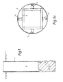
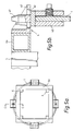
- FIGURES 5a-5c illustrate sectional views of part of the apparatus shown in Figure 4;
- FIGURE 6 illustrates the mode of operation of part of the apparatus shown in Figure 4;
- FIGURE 7 illustrates a sectional view through an adjustable guide frame forming part of the apparatus of Figure 4; and
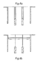
- FIGURE 8 illustrates a typical construction project in which the present invention finds application.
- A presently preferred embodiment of the method of this invention, as applied to the type of pile construction outlined above, will now be described with reference to the drawings.
- (1) As shown in Fig. 1, a temporary casing or
shaft lining tube 1 is installed in the normal manner in aborehole 2. As shown in Fig. 2a, thetube 1 has at its upper end a pair of radially opposed locatingshoes 4 the construction of which is as shown in Figures 2b (a sectional view along lines A-A of Fig. 2a) and 2c (a sectional view along lines B-B of Fig. 2a). Arranged orthogonally with respect to locatingshoes 4 is a pair of support shoes 5. The casing is generally of tubular steel often 3-7 metres long, but which may exceptionally be 20 metres or more in length. - (2) The pile is bored conventionally, either dry or under water or bentonite.
- (3) Concrete is placed either at this point in time or later, generally up to a position several metres below the top of the
temporary casing 1 but above the intended column base level. - (4) A locating device 3 (see Fig 3) is accurately placed on the top of the
casing 1. Thisdevice 3 comprises a rectangular frame containing a plurality ofparallel sight lines 30, typically spaced apart by 25 mm, by means of which the orientation of locatingshoes 4 may be adjusted. - (5) A locating
frame 6 is lowered into thecasing 1 and accurately orientated by means of the device 3 (see Figs. 4 and 5). The frame has a top support unit 6a which overlaps the uppermost section oflining tube 1 as shown in Figure 5a. The method of locating the upper end offrame 6 is illustrated in Figure 5b, which is a section along the lines C-C of Fig. 5a. Locatingshoe 4 comprises a peg-like portion 40 which sits on top of thelining tube 1, and which has adowel 41 arranged to cooperate with abracket 42 through locatingslot 43.Frame 6 is generally 3-7 metres long, although greater lengths can be used to obtain even greater accuracies of location if desired. Theframe 6 may project above thecasing 1 into which it is lowered, but it is often substantially or completely located within the casing. Top section 6a (see Figures 4 and 5a) serves to retain theframe 6 in relation totube 1.Frame 6 is a rectangular space frame the interior space (along and about the longitudinal axis) of which is open. Within theframe 6 there are four adjustable guide frames arranged in two adjacent pairs, those close to the top offrame 6 being identified in Figure 4 as 7 and 8, while those close to the bottom of theframe 6 being identified as 9 and 10. - (6) The
frame 6 is then firmly located in position by means of expandingshoes 11 which thrust on to the casing wall 1 (Fig. 5c) or theunlined bore 2. These shoes are located at two or more levels, and may be actuated mechanically, electrically, pneumatically, hydraulically, or by a combination of one or more of these methods. - (7) The
frame 6 contains two or more pairs of adjustable guide frames (see Figs. 4 and 7). Onepair 7 and 8 is located near the upper end of theframe 6, and anotherpair 9 and 10 near the base of the frame. The guide frames are generally rectangular and are positioned such that the plane of the guide is normal to the axis offrame 6. For each pair of guides, one is located slightly above the other (Figs. 4 and 7); again, for each pair, one includes amovable bar 15 which can be moved in a predetermined direction, say a north-south direction, whereas the other includes a movable bar which can moved in a direction orthogonal to that of the first bar, e.g. in an east-west direction (see Fig. 6). Each individual guide frame can be remotely operated, either mechanically, electrically, pneumatically or hydraulically, or by a combination of one or more of these methods. Once thebars 15 of the adjustable guide frames have been adjusted they cannot be displaced by means of an external force. As illustrated in Fig. 7, each of the adjustable guide frames includes aworm drive 12 driven by ahydraulic motor 13 through adrive gear 14. Themovable bar 15 is, in this embodiment, in the form of arectangular unit 20 carried along the worm drive (12) byshoes 16. Thatside 22 ofunit 20opposite bar 15 is free to slide along abar 17 by means ofshoes 18. The overall permissible movement ofrectangular unit 20 is between the limits set byopposite sides - (8) After the
frame 6 has been positioned as described above, thesteel column 19 is lowered through the guides 7-10 at the top and bottom of the frame. The position of the steel column at or slightly above the top of the frame is then adjusted by means of the upper guide frames 7 and 8, until the column is in the desired position, this being confirmed for example by means of surveying equipment. The lower guide frames 9 and 10 are then adjusted until the column is at the correct inclination (generally vertical). Confirmation of the inclination may be by means of either surveying techniques or by means of spirit levels. - (9) The
steel column 19 is then lowered further into its final position and kept at this level by means of, for example, a crane or a separate clamping arrangement. Concrete may have already been placed (see (3) above) or may be placed after the installation of theframe 6, or even after the final positioning of thesteel column 19. The concrete may be placed by means of a chute, a tremmie pipe or it may be pumped down the pile. Generally the concrete level will be below the lower limits offrame 6. - (10) Once the concrete has set the
frame 6 is removed. The empty bore may be filled with a suitable backfill material and thecasing 1 withdrawn. - The above is an example of the use of this type of frame in a shaft or bore, in which case it would be usual for the frame to be inserted a substantial depth into the shaft/bore. However it is not essential for the frame to be inserted into the shaft/bore. Similarly, whereas it is usual for the steel column to be placed vertically, this system can be used to place the column at any desired inclination. As already mentioned the system can be used to place items such as steel columns and also other items, possibly of different steel sections, but also of concrete (either reinforced or not) or of plastic, or a combination of one or more of these.
- This type of frame can also be used to place similar items into other types of pile, for example into piles of the continuous flight auger type. With this technique the frame is generally used above ground, and is accurately located in plan by the use of a heavy base (either of steel or concrete, or a combination) or by means of separate piles (which may be works piles or supernumary piles). The means of obtaining correct orientation is similar to that already described, as is the means of adjusting the frame to obtain the correct plan position and inclination of the steel column or similar.
- Preferred embodiments of the present invention may offer one or more of the following advantages:
- 1. Precise control of the insertion and positioning of a column (or similar) which is to be partly embedded into a cast in place bored pile.
- 2. The adjustable guide(s) can have controlled clearances within each guide such as to give a predetermined precision of location within a borehole.
- 3. Robust construction of the device is feasible; this allows insertion of a column without deformation to the device.
- 4. Precise orientation of the reference frame, and maintenance of the orientation during use, are possible.
- 5. Accurate positioning both in plan, orientation and inclincation from ground level or above.
- 6. Suitability for use in constructing cast in place piles where the bore is flooded (either partially or wholly) with water or bentonite suspension.
- 7. Suitability for use where a column or the like is to be embedded partly or wholly into a continuous flight auger pile, and sufficient robustness for the location step to to take place above ground.
Claims (9)
Applications Claiming Priority (2)
| Application Number | Priority Date | Filing Date | Title |
|---|---|---|---|
| GB8718390 | 1987-08-04 | ||
| GB878718390A GB8718390D0 (en) | 1987-08-04 | 1987-08-04 | Positioning items in shafts/piles |
Publications (2)
| Publication Number | Publication Date |
|---|---|
| EP0302707A1 EP0302707A1 (en) | 1989-02-08 |
| EP0302707B1 true EP0302707B1 (en) | 1991-06-19 |
Family
ID=10621772
Family Applications (1)
| Application Number | Title | Priority Date | Filing Date |
|---|---|---|---|
| EP19880307140 Expired EP0302707B1 (en) | 1987-08-04 | 1988-08-02 | Method and equipment for accurately positioning items in shafts or piles |
Country Status (5)
| Country | Link |
|---|---|
| EP (1) | EP0302707B1 (en) |
| DE (1) | DE3863322D1 (en) |
| ES (1) | ES2023257B3 (en) |
| GB (1) | GB8718390D0 (en) |
| HK (1) | HK111993A (en) |
Families Citing this family (7)
| Publication number | Priority date | Publication date | Assignee | Title |
|---|---|---|---|---|
| GB2399413B (en) * | 2003-03-14 | 2006-10-18 | Cementation Found Skanska Ltd | Method and apparatus for positioning an element in a borehole |
| GB2399376B (en) | 2003-03-14 | 2005-11-02 | Cementation Found Skanska Ltd | Placing elements in piles |
| CN102587383B (en) * | 2012-03-12 | 2014-06-11 | 长江航运规划设计院 | Positioning method and device for underwater installation of prefabricated crossbeam |
| CN103434933B (en) * | 2013-08-13 | 2015-02-18 | 中国核工业华兴建设有限公司 | Large member hoisting in-position device and in-position method |
| CN110836019A (en) * | 2019-12-04 | 2020-02-25 | 中建二局第一建筑工程有限公司 | Novel lattice column verticality positioner |
| CN115961639B (en) * | 2023-01-30 | 2024-11-12 | 中国电建集团福建省电力勘测设计院有限公司 | A kind of overhead power transmission line platform on water and construction method thereof |
| KR102802183B1 (en) * | 2024-11-21 | 2025-05-02 | (주)유현건설 | Construction method using pile construction equipment for soft ground with limited height |
Family Cites Families (5)
| Publication number | Priority date | Publication date | Assignee | Title |
|---|---|---|---|---|
| US3236055A (en) * | 1963-01-31 | 1966-02-22 | Peter Kiewit Sons Co | Pile driving template |
| US4133154A (en) * | 1977-10-03 | 1979-01-09 | Ruzicka Otto J | System for supporting removable posts |
| FR2481726A1 (en) * | 1980-04-30 | 1981-11-06 | Cticm | Concrete post foundation casing - uses temporary frame to hold post in place until surrounding concrete solidifies |
| DE3151856A1 (en) * | 1981-12-30 | 1983-07-14 | Krings, Josef, 5138 Heinsberg | DEVICE FOR CENTRICALLY PUTING IN A PROTECTIVE POST INTO A PITCH HOLE |
| FR2543197B1 (en) * | 1983-03-25 | 1985-08-16 | Goncalves Pereira Antonio | PROCESS OF IN SITU CONSTRUCTION OF A HOLLOW CONCRETE COLUMN WHICH CAN BE USED AS A TANK OR FOUNDATION |
-
1987
- 1987-08-04 GB GB878718390A patent/GB8718390D0/en active Pending
-
1988
- 1988-08-02 EP EP19880307140 patent/EP0302707B1/en not_active Expired
- 1988-08-02 DE DE8888307140T patent/DE3863322D1/en not_active Expired - Lifetime
- 1988-08-02 ES ES88307140T patent/ES2023257B3/en not_active Expired - Lifetime
-
1993
- 1993-10-21 HK HK111993A patent/HK111993A/en unknown
Also Published As
| Publication number | Publication date |
|---|---|
| HK111993A (en) | 1993-10-29 |
| EP0302707A1 (en) | 1989-02-08 |
| DE3863322D1 (en) | 1991-07-25 |
| GB8718390D0 (en) | 1987-09-09 |
| ES2023257B3 (en) | 1992-01-01 |
Similar Documents
| Publication | Publication Date | Title |
|---|---|---|
| US5123209A (en) | Earth engineering apparatus and method | |
| EP1673509B1 (en) | Method of constructing a pile foundation | |
| JP2837128B2 (en) | Construction method of cast-in-place concrete pile | |
| US3250075A (en) | Method of retaining wall construction and anchoring | |
| PL204665B1 (en) | Method for manufacturing a ground slab field and a ground slab field | |
| US4152089A (en) | Method and apparatus for forming a cast-in-place support column | |
| US7484913B2 (en) | Placing elements in piles | |
| EP0302707A1 (en) | Method and equipment for accurately positioning items in shafts or piles | |
| US20060254068A1 (en) | Method and apparatus for monitoring element alignment | |
| KR102494824B1 (en) | CIP retaining wall and water barrier construction method using PHC-pile | |
| JPH0768705B2 (en) | Soil retaining method and its retaining pile | |
| JP3129676B2 (en) | Piling columns in building structures using piles as pillars | |
| JP4925267B2 (en) | Independent foundation and its construction method | |
| GB2261891A (en) | Installing columns e.g. below ground | |
| EP0084921B1 (en) | Piles | |
| GB2205121A (en) | Underpinning buildings by using, in situ, cast piles | |
| EP0580264A1 (en) | Method for providing deep partition walls in the ground and an excavating apparatus for use in this method | |
| GB2255990A (en) | Underpinning buildings | |
| EP3899147B1 (en) | Method and kit for manufacturing foundations for uprights by using sheets embedded by vibration or by percussion | |
| JPH0128167B2 (en) | ||
| EP1348812A1 (en) | Building methods and apparatus | |
| JP3238368B2 (en) | Fixing method of pillar for retaining wall block and guide member used therefor | |
| JPS5920822B2 (en) | Seismic reinforcement method for embankments | |
| RU1794192C (en) | Method for constructing pits | |
| JP3537641B2 (en) | Basement submersion method and its equipment |
Legal Events
| Date | Code | Title | Description |
|---|---|---|---|
| PUAI | Public reference made under article 153(3) epc to a published international application that has entered the european phase |
Free format text: ORIGINAL CODE: 0009012 |
|
| AK | Designated contracting states |
Kind code of ref document: A1 Designated state(s): DE ES FR GB IT |
|
| 17P | Request for examination filed |
Effective date: 19890728 |
|
| 17Q | First examination report despatched |
Effective date: 19900427 |
|
| GRAA | (expected) grant |
Free format text: ORIGINAL CODE: 0009210 |
|
| AK | Designated contracting states |
Kind code of ref document: B1 Designated state(s): DE ES FR GB IT |
|
| PG25 | Lapsed in a contracting state [announced via postgrant information from national office to epo] |
Ref country code: IT Free format text: LAPSE BECAUSE OF FAILURE TO SUBMIT A TRANSLATION OF THE DESCRIPTION OR TO PAY THE FEE WITHIN THE PRE;WARNING: LAPSES OF ITALIAN PATENTS WITH EFFECTIVE DATE BEFORE 2007 MAY HAVE OCCURRED AT ANY TIME BEFORE 2007. THE CORRECT EFFECTIVE DATE MAY BE DIFFERENT FROM THE ONE RECORDED.SCRIBED TIME-LIMIT Effective date: 19910619 |
|
| REF | Corresponds to: |
Ref document number: 3863322 Country of ref document: DE Date of ref document: 19910725 |
|
| EN | Fr: translation not filed | ||
| PG25 | Lapsed in a contracting state [announced via postgrant information from national office to epo] |
Ref country code: FR Effective date: 19911108 |
|
| REG | Reference to a national code |
Ref country code: ES Ref legal event code: FG2A Ref document number: 2023257 Country of ref document: ES Kind code of ref document: B3 |
|
| PLBE | No opposition filed within time limit |
Free format text: ORIGINAL CODE: 0009261 |
|
| STAA | Information on the status of an ep patent application or granted ep patent |
Free format text: STATUS: NO OPPOSITION FILED WITHIN TIME LIMIT |
|
| PGFP | Annual fee paid to national office [announced via postgrant information from national office to epo] |
Ref country code: GB Payment date: 19920602 Year of fee payment: 5 |
|
| 26N | No opposition filed | ||
| PGFP | Annual fee paid to national office [announced via postgrant information from national office to epo] |
Ref country code: ES Payment date: 19920623 Year of fee payment: 5 |
|
| REG | Reference to a national code |
Ref country code: FR Ref legal event code: ST |
|
| PGFP | Annual fee paid to national office [announced via postgrant information from national office to epo] |
Ref country code: DE Payment date: 19920707 Year of fee payment: 5 |
|
| PG25 | Lapsed in a contracting state [announced via postgrant information from national office to epo] |
Ref country code: GB Effective date: 19930802 |
|
| PG25 | Lapsed in a contracting state [announced via postgrant information from national office to epo] |
Ref country code: ES Free format text: LAPSE BECAUSE OF NON-PAYMENT OF DUE FEES Effective date: 19930803 |
|
| GBPC | Gb: european patent ceased through non-payment of renewal fee |
Effective date: 19930802 |
|
| PG25 | Lapsed in a contracting state [announced via postgrant information from national office to epo] |
Ref country code: DE Effective date: 19940503 |
|
| REG | Reference to a national code |
Ref country code: ES Ref legal event code: FD2A Effective date: 19940912 |