EP0302549A2 - Storing cassette for a disc-like information carrier - Google Patents
Storing cassette for a disc-like information carrier Download PDFInfo
- Publication number
- EP0302549A2 EP0302549A2 EP88201575A EP88201575A EP0302549A2 EP 0302549 A2 EP0302549 A2 EP 0302549A2 EP 88201575 A EP88201575 A EP 88201575A EP 88201575 A EP88201575 A EP 88201575A EP 0302549 A2 EP0302549 A2 EP 0302549A2
- Authority
- EP
- European Patent Office
- Prior art keywords
- tray
- information carrier
- cover part
- holder
- basic position
- Prior art date
- Legal status (The legal status is an assumption and is not a legal conclusion. Google has not performed a legal analysis and makes no representation as to the accuracy of the status listed.)
- Withdrawn
Links
Images

Classifications
-
- G—PHYSICS
- G11—INFORMATION STORAGE
- G11B—INFORMATION STORAGE BASED ON RELATIVE MOVEMENT BETWEEN RECORD CARRIER AND TRANSDUCER
- G11B17/00—Guiding record carriers not specifically of filamentary or web form, or of supports therefor
- G11B17/22—Guiding record carriers not specifically of filamentary or web form, or of supports therefor from random access magazine of disc records
-
- G—PHYSICS
- G11—INFORMATION STORAGE
- G11B—INFORMATION STORAGE BASED ON RELATIVE MOVEMENT BETWEEN RECORD CARRIER AND TRANSDUCER
- G11B33/00—Constructional parts, details or accessories not provided for in the other groups of this subclass
- G11B33/02—Cabinets; Cases; Stands; Disposition of apparatus therein or thereon
- G11B33/04—Cabinets; Cases; Stands; Disposition of apparatus therein or thereon modified to store record carriers
- G11B33/0405—Cabinets; Cases; Stands; Disposition of apparatus therein or thereon modified to store record carriers for storing discs
- G11B33/0411—Single disc boxes
- G11B33/0422—Single disc boxes for discs without cartridge
Definitions
- the invention relates to a storage cassette with a bottom part, a hinged lid part and a tray which can be inserted into the bottom part for receiving an insertable plate-shaped information carrier which can be held on the tray by means of at least three holders provided on the tray, at least one of which is supported on its outer edge Bracket is designed to be movable and in its basic position presses the information carrier under spring force against the other brackets and fixes it in its position.
- An element for receiving and holding a rigid circular information plate consists of a tray to be inserted into a storage cassette with a receiving trough which has holders for fixing the information plate.
- the brackets act opposite each other on the edge of an inserted Information plate. At least one of these brackets is resilient.
- the tray has a double function, namely to hold the information plate while it is being stored in the storage cassette, and it additionally enables the information plate to be transferred from the cassette into the playback device without contact. If necessary, however, the disc can also be removed from the tray by hand and inserted into the player.
- the resilient holder can spring back in the event of vibrations in such a way that the plate-shaped information carrier is released. This is undesirable since in this case the information carrier can flip back and forth in the packaging and be damaged.
- At least one locking element is provided on the cover part, which locks the resilient holder in its basic position when the cover is closed.
- Such a locking element provided on the cover part prevents the movable and resilient holder from springing back. This also applies to mechanical shocks. Characterized in that the locking element is provided on the cover part, the resilient holder is automatically locked in its basic position when the cover part is closed on the base part. Nevertheless, if the cover part is open, removal of the plate-shaped information carrier is possible, if desired, by manually moving the resilient holder out of its basic position, so that the plate-shaped information carrier is released.
- the locking element is advantageously arranged such that it does not exert any force on the resilient holder as long as it is in its basic position. This ensures that no additional forces are exerted on an inserted plate-shaped information carrier, which could lead to twisting thereof.
- the locking element can be produced economically, since only a corresponding device is to be provided on the cover part, which can be injected together with the cover part and thus requires almost no additional effort.
- the locking element on the cover part Has the form of a locking lug, which engages behind the movable holder in the closed state of the cover so that it cannot be moved from its basic position.
- a locking element according to the invention can now advantageously be attached to the cover part in such a way that it engages behind the movable holder so that it cannot be moved out of its basic position.
- a locking lug is provided on the cover part, which engages behind the movable holder when the cover is closed. It is thus safely avoided in a simple manner that when the cover is closed, that is to say, for example during transport, the movable holder can move back from the basic position and release an inserted plate-shaped information carrier.
- Another advantage of such an arrangement is that no additional measures for securing the transport are required on the tray or on the movable holder attached to the tray. Rather, it is sufficient to provide a locking lug on the cover part in the form described above.
- a handle strip is provided on the insertable tray in the region of the axis of rotation of the cover part and that the movable holder on the tray and the locking lug on the cover part are arranged in the region of the handle bar.
- a grip strip is often provided on trays of the type described at the outset for receiving plate-shaped information carriers. If both the handle bar on the tray and the movable holder are arranged in such a way that they are arranged in the region of the axis of rotation of the cover part, the locking lug is also arranged in the area of the handle bar.
- the advantage here is that the locking lug is arranged in an area of the cover part in which it does not interfere. This is important because a device, for example for receiving a text booklet, is often provided in the cover part. If the locking lug is provided in the area of the axis of rotation of the cover part, the insertion of such a text booklet is not hindered.
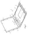
- a storage cassette shown in Fig. 1 is used to hold and store plate-shaped information carriers, in particular optically readable information carriers, such as a compact disc.
- the storage cassette 1 has a base part 2 and a foldable cover part 3. Both the bottom part 2 and the cover part 3 usually consist of a transparent plastic.
- the cover part 3 is rotatably connected to the bottom part 2.
- a tray 4 is inserted for receiving a plate-shaped information carrier.
- This tray 4 is used to hold an information carrier (not shown in the figure).
- the tray 4 has a circular recess 5 into which the information carrier can be inserted.
- a grip bar 6 is arranged on one side next to the tub 5. This grip strip 6 is located in the region of the axis of rotation of the cover part 3 which is hingedly mounted on the base part.
- brackets In order to fix a plate-shaped information carrier (not shown in FIG. 1) inserted into the tub 5, three brackets are provided on the edge of the tub 5, which hold an inserted information carrier on its outer edge.
- Two brackets 7 and 8 are arranged opposite the handle bar 6 on the outer edge of the tub 5. These brackets 7 and 8 are designed to be immobile. The brackets 7 and 8 are in such a distance from each other that an inserted information carrier can move back and forth as little as possible.
- a third bracket 9 is located opposite the brackets 7 and 8, that is to say in the region of the handle bar 6 on the edge of the tub 5.
- the bracket 9 In contrast to the brackets 7 and 8, the bracket 9 is designed to be movable.
- the holder 9 is provided on a leaf spring 10.
- an information plate (not shown in the figure) is clamped between the holders 7, 8 and 9.
- the bracket 9 can be moved back from its basic position by springing back of the leaf spring 10, so that an information carrier clamped between the brackets 7, 8 and 9 can be removed from the tub 5.
- Such removal can either be done manually, by moving the leaf spring 10 and the holder 9 back manually, or else automatically in one device.
- the entire tray 4 together with an inserted information carrier and fixed between the holders 7, 8 and 9 is inserted into a playback device.
- the leaf spring 10 and thus also the holder 9 are then moved back by a device to be provided accordingly, so that the inserted plate-shaped information carrier is released and can be played.
- a recess 11 is provided in the tub 5, which allows a plate-shaped information carrier inserted into the tub 5 to be scanned from below, for example by means of a laser beam.
- a locking lug 12 is provided on the cover part 3 in the region of its axis of rotation on the base part 2.
- This locking lug 12 protrudes approximately vertically from the cover part 3 and is arranged thereon so that it engages behind the holder 9 on the leaf spring 9 when the cover 3 is closed.
- a recess 11 is provided behind the bracket 10 in the leaf spring 10, in which the locking lug 12 can engage.
- the locking lug 12 is thus arranged so that they engage in this recess 12 when a plate-shaped information carrier is clamped between the brackets 7, 8 and 9 in the tub 5. The holder 9 is then locked in this basic position and remains when it acts on it Forces in this position.
- the locking lug 12 since it is provided on the cover part, does not in any way hinder the normal operation of the tray, i.e. an inserted information carrier can still be removed from the tray 5 of the tray 4 both manually and mechanically in a corresponding player.
- the locking lug 12 is provided in the region of the axis of rotation of the cover part, inserting a text booklet (not shown in the figure) into the cover part 3 is not hindered.
- 3 receptacles 14 are provided on the side walls of the cover part, behind which a text booklet can be pushed.
- FIG. 2 shows a section of the storage cassette shown in FIG. 1 together with the inserted tray 4 in section along the line II-II.
- FIG. 2 shows the base part 2 with the cover part 3 opened with a tray 4 inserted in the base part 2.
- a plate-shaped information carrier 21 is inserted into the tray 4.
- the plate-shaped information carrier 21 is fixed behind the movable holder 9.
- the holder 9 is provided on the leaf spring 10, which has a tongue 10a pointing in the direction of the grip bar 6.
- a recess 11 is provided in this tongue 10a of the leaf spring 10.
- the holder 9 is shown in its basic position. In this basic position, a plate-shaped information carrier 21 is clamped behind the holder 9. On the other side of the information carrier is this not shown in Fig. 2 clamped between the brackets 7 and 8 of the tray 4 (see Fig. 1).
- the holder 9 together with the leaf spring 10 should now be fixed in this basic position. This is done by means of the locking lug 12 provided on the cover part 3, which engages in the recess 11 in the lug 10a of the leaf spring 10.
- FIG. 3 shows the storage cassette 1 according to FIG. 2 in the closed state of the cover 5.
- the locking lug 12 provided on the cover part 3 engages in the recess 11 of the tongue 10a of the leaf spring 10. In this way, the movable bracket 9 is fixed in its basic position.
- the locking lug 12 engages with a little play in the recess 11, so that no force is exerted on the leaf spring 10 and thus on the movable holder 9, which could lead to twisting of the inserted plate-shaped information carrier 21.
- the plate-shaped information carrier 21 is stored in the storage cassette 1 in such a way that it is securely fixed behind the brackets 7, 8 and 9 even in the event of vibrations acting on the storage cassette and there is therefore no danger that the information carrier will be damaged or twisted.
Abstract
Description
Die Erfindung bezieht sich auf eine Aufbewahrungskassette mit einem Bodenteil, einem klappbaren Deckelteil und einem in das Bodenteil einlegbaren Tablett zur Aufnahme eines einlegbaren plattenförmigen Informationsträgers, der mittels wenigstens dreier, an dem Tablett vorgesehenen Halterungen über seinen äußeren Rand am Tablett halterbar ist, wobei wenigstens eine Halterung beweglich ausgebildet ist und in ihrer Grundstellung den Informationsträger unter Federkraft gegen die übrigen Halterungen drückt und ihn in seiner Lage fixiert.The invention relates to a storage cassette with a bottom part, a hinged lid part and a tray which can be inserted into the bottom part for receiving an insertable plate-shaped information carrier which can be held on the tray by means of at least three holders provided on the tray, at least one of which is supported on its outer edge Bracket is designed to be movable and in its basic position presses the information carrier under spring force against the other brackets and fixes it in its position.
Derartige Aufbewahrungskassetten sind beispielsweise aus der europäischen Patentanmeldung 0 188 663 bekannt. Ein Element zur Aufnahme und Halterung einer steifen kreisförmigen Informationsplatte besteht dabei aus einem in eine Aufbewahrungskassette einzubringenden Tablett mit einer Aufnahmewanne, die Halterungen zum Fixieren der Informationsplatte aufweist. Die Halterungen wirken einander gegenüberliegend auf den Rand einer eingelegten Informationsplatte ein. Wenigstens eine dieser Halterungen ist federnd ausgebildet. Das Tablett hat eine doppelte Funktion, nämlich das Festhalten der Informationsplatte während der Aufbewahrung in der Aufbewahrungskassette, und es ermöglicht zusätzlich das berührungslose Überführen der Informationsplatte von der Kassette in die Abspieleinrichtung. Bei Bedarf kann die Platte jedoch auch dem Tablett von Hand entnommen und in das Abspielgerät eingeführt werden.Storage cartridges of this type are known, for example, from European patent application 0 188 663. An element for receiving and holding a rigid circular information plate consists of a tray to be inserted into a storage cassette with a receiving trough which has holders for fixing the information plate. The brackets act opposite each other on the edge of an inserted Information plate. At least one of these brackets is resilient. The tray has a double function, namely to hold the information plate while it is being stored in the storage cassette, and it additionally enables the information plate to be transferred from the cassette into the playback device without contact. If necessary, however, the disc can also be removed from the tray by hand and inserted into the player.
Bei derartigen Tabletts mit wenigstens einer federnd ausgebildeten Halterung kann die federnd ausgebildete Halterung bei Erschütterungen derart zurückfedern, daß der plattenförmige Informationsträger freikommt. Dieses ist unerwünscht, da der Informationsträger in diesem Falle in der Verpackung hin und her schlagen und beschädigt werden kann.In such trays with at least one resilient holder, the resilient holder can spring back in the event of vibrations in such a way that the plate-shaped information carrier is released. This is undesirable since in this case the information carrier can flip back and forth in the packaging and be damaged.
Es ist Aufgabe der Erfindung, eine Aufbewahrungskassette mit einem einlegbaren Tablett der eingangs genannten Art dahingehend zu verbessern, daß ein in das Tablett eingelegter, plattenförmiger Informationsträger auch unter Einwirkung von Erschütterungen auf das Tablett sicher in den Halterungen fixiert ist, ohne daß eine Entnahme des Informationsträgers aus dem Tablett erschwert wird.It is an object of the invention to improve a storage cassette with an insertable tray of the type mentioned at the outset in such a way that a plate-shaped information carrier inserted into the tray is securely fixed in the holders even under the influence of vibrations on the tablet, without the information carrier being removed from the tray is difficult.
Diese Aufgabe ist erfindungsgemäß dadurch gelöst, daß an dem Deckelteil wenigstens ein Verriegelungselement vorgesehen ist, welches in zugeklapptem Zustand des Deckels die federnd ausgebildete Halterung in ihrer Grundstellung arretiert.This object is achieved in that at least one locking element is provided on the cover part, which locks the resilient holder in its basic position when the cover is closed.
Mittels eines derartigen am Deckelteil vorgesehenen Verriegelungselementes wird ein Zurückfedern der beweglich und federnd ausgebildeten Halterung verhindert. Dies gilt auch bei Einwirkung mechanischer Erschütterungen. Dadurch, daß das Verriegelungselement am Deckelteil vorgesehen ist, wird beim Schließen des Deckelteils auf das Bodenteil automatisch die federnd ausgebildete Halterung in ihrer Grundstellung arretiert. Gleichwohl ist bei geöffnetem Deckelteil gewünschtenfalls eine Entnahme des plattenförmigen Informationsträgers möglich, in dem die federnd ausgebildete Halterung manuell aus ihrer Grundstellung wegbewegt wird, so daß der plattenförmige Informationsträger freigegeben wird.Such a locking element provided on the cover part prevents the movable and resilient holder from springing back. This also applies to mechanical shocks. Characterized in that the locking element is provided on the cover part, the resilient holder is automatically locked in its basic position when the cover part is closed on the base part. Nevertheless, if the cover part is open, removal of the plate-shaped information carrier is possible, if desired, by manually moving the resilient holder out of its basic position, so that the plate-shaped information carrier is released.
Das Verriegelungselement ist vorteilhafter Weise derart angeordnet, daß es auf die federnd ausgebildete Halterung solange keine Kraft ausübt, wie diese sich in ihrer Grundstellung befindet. Damit ist sichergestellt, daß auf einen eingelegten plattenförmigen Informationsträger keine zusätzlichen Kräfte ausgeübt werden, welche zu Verwindungen desselben führen könnten.The locking element is advantageously arranged such that it does not exert any force on the resilient holder as long as it is in its basic position. This ensures that no additional forces are exerted on an inserted plate-shaped information carrier, which could lead to twisting thereof.
Das Verriegelungselement ist wirtschaftlich herstellbar, da lediglich an dem Deckelteil eine entsprechende Vorrichtung vorzusehen ist, die zusammen mit dem Deckelteil gespritzt werden kann und somit nahezu keinen zusätzlichen Aufwand erfordert.The locking element can be produced economically, since only a corresponding device is to be provided on the cover part, which can be injected together with the cover part and thus requires almost no additional effort.
Nach einer weiteren Ausgestaltung der Erfindung ist vorgesehen, daß das Verriegelungselement an dem Deckelteil die Form einer Sperrnase aufweist, die in zugeklapptem Zustand des Deckels so hinter die bewegliche Halterung greift, daß diese nicht aus ihrer Grundstellung bewegbar ist.According to a further embodiment of the invention it is provided that the locking element on the cover part Has the form of a locking lug, which engages behind the movable holder in the closed state of the cover so that it cannot be moved from its basic position.
Die bewegliche Halterung fixiert in ihrer Grundstellung einen eingelegten plattenförmigen Informationsträger so, daß dieser nicht entnehmbar ist. Zur Entnahme des plattenförmigen Informationsträgers ist die bewegliche Halterung aus ihrer Grundstellung gegen die Federkraft zu bewegen. Ein erfindungsgemäßes Verriegelungselement kann nun vorteilhafter Weise so an dem Deckelteil angebracht werden, daß es hinter die bewegliche Halterung greift, so daß diese nicht aus ihrer Grundstellung bewegbar ist. Dazu wird an dem Deckelteil eine Sperrnase vorgesehen, die in zugeklapptem Zustand des Deckels hinter die bewegliche Halterung greift. Es ist so auf einfache Weise sicher vermieden, daß in zugeklapptem Zustand des Deckels, also beispielsweise beim Transport, die bewegliche Halterung sich aus der Grundstellung zurückbewegen und einen eingelegten plattenförmigen Informationsträger freigeben kann. Ein weiterer Vorteil einer solchen Anordnung besteht darin, daß an dem Tablett bzw. an der an dem Tablett angebrachten beweglichen Halterung keine zusätzlichen Maßnahmen zur Transportsicherung erforderlich sind. Es genügt vielmehr, eine Sperrnase an dem Deckelteil in der oben beschriebenen Form vorzusehen.In its basic position, the movable holder fixes an inserted plate-shaped information carrier so that it cannot be removed. To remove the plate-shaped information carrier, the movable holder must be moved from its basic position against the spring force. A locking element according to the invention can now advantageously be attached to the cover part in such a way that it engages behind the movable holder so that it cannot be moved out of its basic position. For this purpose, a locking lug is provided on the cover part, which engages behind the movable holder when the cover is closed. It is thus safely avoided in a simple manner that when the cover is closed, that is to say, for example during transport, the movable holder can move back from the basic position and release an inserted plate-shaped information carrier. Another advantage of such an arrangement is that no additional measures for securing the transport are required on the tray or on the movable holder attached to the tray. Rather, it is sufficient to provide a locking lug on the cover part in the form described above.
Nach einer weiteren Ausgestaltung der Erfindung ist vorgesehen, daß an dem einlegbaren Tablett im Bereich der Drehachse des Deckelteils eine Griffleiste vorgesehen ist und daß die bewegliche Halterung am Tablett und die Sperrnase am Deckelteil im Bereich der Griffleiste angeordnet sind.According to a further embodiment of the invention it is provided that a handle strip is provided on the insertable tray in the region of the axis of rotation of the cover part and that the movable holder on the tray and the locking lug on the cover part are arranged in the region of the handle bar.
An Tabletts der eingangs beschriebenen Art zur Aufnahme plattenförmiger Informationsträger ist häufig eine Griffleiste vorgesehen. Werden nun sowohl die Griffleiste an dem Tablett, wie auch die bewegliche Halterung so angeordnet, daß sie im Bereich der Drehachse des Deckelteils angeordnet sind, so ist auch die Sperrnase im Bereich der Griffleiste angeordnet. Dabei ergibt sich der Vorteil, daß die Sperrnase in einem Bereich des Deckelteils angeordnet ist, in dem sie nicht stört. Dies ist deshalb von Bedeutung, weil in dem Deckelteil häufig eine Vorrichtung beispielsweise zur Aufnahme eines Textheftes vorgesehen ist. Ist die Sperrnase im Bereich der Drehachse des Deckelteils vorgesehen, so wird das Einlegen eines solchen Textheftes nicht behindert.A grip strip is often provided on trays of the type described at the outset for receiving plate-shaped information carriers. If both the handle bar on the tray and the movable holder are arranged in such a way that they are arranged in the region of the axis of rotation of the cover part, the locking lug is also arranged in the area of the handle bar. The advantage here is that the locking lug is arranged in an area of the cover part in which it does not interfere. This is important because a device, for example for receiving a text booklet, is often provided in the cover part. If the locking lug is provided in the area of the axis of rotation of the cover part, the insertion of such a text booklet is not hindered.
Ein Ausführungsbeispiel der Erfindung wird anhand der Zeichnungen näher erläutert. Es zeigen:
- Fig. 1 eine Aufbewahrungskassette mit einem Bodenteil, einem mit einem Verriegelungselement versehenen, klappbaren Deckelteil und einem in das Bodenteil eingelegten Tablett,
- Fig. 2 die Aufbewahrungskassette nach Fig. 1 im Schnitt entlang der Linie II-II und eingelegtem Informationsträger,
- Fig. 3 die Aufbewahrungskassette im Schnitt entsprechend der Fig. 2 in zugeklapptem Zustand des Deckelteils.
- 1 shows a storage cassette with a bottom part, a hinged lid part provided with a locking element and a tray inserted into the bottom part,
- 2 shows the storage cassette according to FIG. 1 in section along the line II-II and inserted information carrier,
- Fig. 3 shows the storage cassette in section according to FIG. 2 in the closed state of the cover part.
Eine in Fig. 1 dargestellte Aufbewahrungskassette dient der Aufnahme und Lagerung von plattenförmigen Informationsträgern, insbesondere optisch auslesbaren Informationsträgern, wie beispielsweise einer Compact-Disc. Die Aufbewahrungskassette 1 weist ein Bodenteil 2 und ein klappbares Deckelteil 3 auf. Sowohl das Bodenteil 2 wie auch das Deckelteil 3 bestehen meist aus einem transparenten Kunststoff. Das Deckelteil 3 ist drehbar gelagert mit dem Bodenteil 2 verbunden. In das Bodenteil 2 ist ein Tablett 4 zur Aufnahme eines plattenförmigen Informationsträgers eingelegt. Dieses Tablett 4 dient der Aufnahme eines in der Fig. nicht dargestellten Informationsträgers. Dazu weist das Tablett 4 eine kreisförmige Vertiefung 5 auf, in die der Informationsträger einlegbar ist. Auf einer Seite neben der Wanne 5 ist eine Griffleiste 6 angeordnet. Diese Griffleiste 6 befindet sich im Bereich der Drehachse des an dem Bodenteil klappbar gelagerten Deckelteils 3.A storage cassette shown in Fig. 1 is used to hold and store plate-shaped information carriers, in particular optically readable information carriers, such as a compact disc. The
Zur Fixierung eines in der Fig. 1 nicht dargestellten in die Wanne 5 eingelegten plattenförmigen Informationsträgers sind am Rand der Wanne 5 drei Halterungen vorgesehen, welche einen eingelegten Informationsträger an dessen äußerem Rand festhalten. Zwei Halterungen 7 und 8 sind der Griffleiste 6 gegenüberliegend am äußeren Rand der Wanne 5 angeordnet. Diese Halterungen 7 und 8 sind unbeweglich ausgeführt. Die Halterungen 7 und 8 sind in einem solchen Abstand voneinander angeordnet, daß ein eingelegter Informationsträger sich möglichst wenig hin und her bewegen kann. Eine dritte Halterung 9 ist den Halterungen 7 und 8 gegenüberliegend, d.h. also im Bereich der Griffleiste 6 am Rande der Wanne 5 angeordnet. Im Gegensatz zu den Halterungen 7 und 8 ist die Halterung 9 beweglich ausgeführt. Dazu ist die Halterung 9 auf einer Blattfeder 10 vorgesehen. In der Ruhestellung der Blattfeder 10 und der Halterung 9 ist eine in der Fig. nicht dargestellte Informationsplatte zwischen den Halterungen 7, 8 und 9 eingeklemmt. Die Halterung 9 kann mittels Zurückfedern der Blattfeder 10 aus ihrer Grundstellung zurückbewegt werden, so daß ein zwischen den Halterungen 7, 8 und 9 eingeklemmter Informationsträger aus der Wanne 5 entnommen werden kann. Eine derartige Entnahme kann entweder per Hand geschehen, indem die Blattfeder 10 und die Halterung 9 manuell zurückbewegt werden, oder aber auch automatisch in einem Gerät. In diesem Falle wird das gesamte Tablett 4 mitsamt einem eingelegten und zwischen den Halterungen 7, 8 und 9 fixierten Informationsträger in ein Abspielgerät eingeschoben. In dem Abspielgerät wird dann durch eine entsprechend vorzusehene Vorrichtung die Blattfeder 10 und damit auch die Halterung 9 zurückbewegt, so daß der eingelegte plattenförmige Informationsträger freigegeben wird und abspielbar ist. Zu diesem Zwecke ist in der Wanne 5 eine Aussparung 11 vorgesehen, welche es gestattet, eine in die Wanne 5 eingelegten plattenförmigen Informationsträger von unten her, beispielsweise mittels eines Laserstrahls, abzutasten.In order to fix a plate-shaped information carrier (not shown in FIG. 1) inserted into the
Bei derartigen Aufbewahrungskassetten und in diese einlegbaren Tabletts besteht nun das Problem, daß ein Zurückfedern der Blattfeder 10 mitsamt der an ihr vorgesehenen Halterung 9 auch unerwünschter Weise beim Transport möglich ist. Ein beim Transport in die Wanne 5 eingelegter und zwischen den Halterungen 7, 8 und 9 fixierter Informationsträger übt bei auf das Tablett ausgeübten Erschütterungen entsprechende Kräfte auf die Halterung 9 und damit auch auf die Blattfeder 10 aus, so daß diese gegebenenfalls sich nach außen aus ihrer Grundstellung heraus wegbewegen können. In diesem Falle kann ein eingelegter plattenförmiger Informationsträger aus wenigstens einer der Halterungen 7, 8 oder 9 herausbewegt werden, so daß er (bei zugeklapptem Deckelteil 3) in der Aufbewahrungskassette lose hin und her schlägt. Dies ist zu vermeiden, da gerade bei optisch auslesbaren Informationsträgern ein Zerkratzen oder ähnliches deren Oberflächen unbedingt vermieden werden muß. Außerdem besteht in diesem Falle die Gefahr der Verwindung des Informationsträgers.With such storage cassettes and trays that can be inserted into them, there is now the problem that springing back of the
Zur Vermeidung dieses Problems ist erfindungsgemäß an dem Deckelteil 3 im Bereich dessen Drehachse an dem Bodenteil 2 eine Sperrnase 12 vorgesehen. Diese Sperrnase 12 steht etwa senkrecht aus dem Deckelteil 3 heraus und ist an diesem so angeordnet, daß sie in zugeklapptem Zustand des Deckels 3 hinter die Halterung 9 auf der Blattfeder 9 greift. Zu diesem Zwecke ist hinter der Halterung 10 in der Blattfeder 10 eine Aussparung 11 vorgesehen, in die die Sperrnase 12 eingreifen kann. Die Sperrnase 12 ist also so angeordnet, daß sie in diese Aussparung 12 eingreifen, wenn in die Wanne 5 ein plattenförmiger Informationsträger zwischen den Halterungen 7, 8 und 9 eingeklemmt ist. Die Halterung 9 ist dann in dieser Grundstellung arretiert und verbleibt bei auf sie einwirkenden Kräften in dieser Stellung.To avoid this problem, according to the invention a locking
Die Sperrnase 12 behindert, da sie am Deckelteil vorgesehen ist, den normalen Betrieb des Tabletts in keiner Weise, d.h. ein eingelegter Informationsträger kann nach wie vor sowohl manuell, wie auch mechanisch in einem entsprechenden Abspielgerät aus der Wanne 5 des Tabletts 4 entnommen werden.The locking
Da die Sperrnase 12 im Bereich der Drehachse des Deckelteils vorgesehen ist, wird ein Einlegen eines in der Fig. nicht dargestellten Textheftes in das Deckelteil 3 nicht behindert. Zu diesem Zwecke sind an den Seitenwänden des Deckelteils 3 Aufnahmen 14 vorgesehen, hinter die ein Textheft schiebbar ist.Since the locking
In Fig. 2 ist ein Ausschnitt der in Fig. 1 dargestellten Aufbewahrungskassette mitsamt dem eingelegten Tablett 4 im Schnitt entlang der Linie II-II dargestellt. In der Fig. 2 ist das Bodenteil 2 mit dem aufgeklappten Deckelteil 3 mit einem in das Bodenteil 2 eingelegten Tablett 4 dargestellt. In das Tablett 4 ist ein plattenförmiger Informationsträger 21 eingelegt. Der plattenförmige Informationsträger 21 ist hinter der beweglichen Halterung 9 fixiert. Die Halterung 9 ist an der Blattfeder 10 vorgesehen, die eine in Richtung der Griffleiste 6 weisende Zunge 10a aufweist. In dieser Zunge 10a der Blattfeder 10 ist eine Aussparung 11 vorgessehen.FIG. 2 shows a section of the storage cassette shown in FIG. 1 together with the inserted
In Fig. 2 ist die Halterung 9 in ihrer Grundstellung dargestellt. In dieser Grundstellung ist ein plattenförmiger Informationsträger 21 hinter der Halterung 9 eingeklemmt. Auf der anderen Seite des Informationsträgers ist dieser in der Fig. 2 nicht dargestellter Weise zwischen den Halterungen 7 und 8 des Tabletts 4 eingeklemmt (siehe Fig. 1).2, the
Für einen Transport soll nun die Halterung 9 mitsamt der Blattfeder 10 in dieser Grundstellung fixiert werden. Dies geschieht mittels der an dem Deckelteil 3 vorgesehenen Sperrnase 12, welche in die Aussparung 11 in der Nase 10a der Blattfeder 10 eingreift.For transport, the
In Fig. 3 ist die Aufbewahrungskassette 1 nach Fig. 2 in zugeklapptem Zustand des Deckels 5 dargestellt. Die an dem Deckelteil 3 vorgesehene Sperrnase 12 greift in die Aussparung 11 der Zunge 10a der Blattfeder 10 ein. Auf diese Weise ist die bewegliche Halterung 9 in ihrer Grundstellung fixiert. Die Sperrnase 12 greift mit etwas Spiel in die Aussparung 11 ein, so daß auf die Blattfeder 10 und damit auf die bewegliche Halterung 9 keine Kraft ausgeübt wird, die zu einem Verwinden des eingelegten plattenförmigen Informationsträgers 21 führen könnte.3 shows the
In dem in Fig. 3 dargestellten Zustand, der auch beim Transport gegeben ist, ist der plattenförmige Informationsträger 21 in der Aufbewahrungskassette 1 in der Weise gelagert, daß er auch bei auf die Aufbewahrungskassette einwirkenden Erschütterungen sicher hinter den Halterungen 7, 8 und 9 fixiert ist und somit nicht die Gefahr besteht, daß der Informationsträger beschädigt wird oder sich verwindet.In the state shown in Fig. 3, which is also given during transport, the plate-shaped
Claims (3)
dadurch gekennzeichnet, daß an dem Deckelteil (3) wenigstens ein Verriegelungselement (12) vorgesehen ist, welches in zugeklapptem Zustand des Deckels (3) die federnd ausgebildete Halterung(8) in ihrer Grundstellung arretiert.1. Storage cassette with a base part (2), a foldable cover part (3) and a tray (4) which can be inserted into the base part for receiving an insertable plate-shaped information carrier which is attached by means of at least three holders (7, 8, 9) provided on the tray. can be held over the outer edge of the tray, at least one holder (9) being designed to be movable and in its basic position presses the information carrier against the other holders under spring force and fixes it in its position,
characterized in that at least one locking element (12) is provided on the cover part (3) which, when the cover (3) is closed, locks the spring-mounted holder (8) in its basic position.
dadurch gekennzeichnet, daß das Verriegelungselement (12) an dem Deckelteil (3) die Form einer Sperrnase aufweist, die bei zugeklapptem Deckel (3) in der Weise hinter die bewegliche Halterung (9) greift, daß diese nicht aus ihrer Grundstellung bewegbar ist.2. Storage cassette according to claim 1,
characterized in that the locking element (12) on the cover part (3) has the form of a locking lug which, when the cover (3) is closed, engages behind the movable holder (9) in such a way that it cannot be moved from its basic position.
dadurch gekennzeichnet, daß an dem einlegbaren Tablett (14) im Bereich der Drehachse des Deckelteils (3) eine Griffleiste (6) vorgesehen ist und daß die bewegliche Halterung (9) am Tablett (14) und die Sperrnase (12) am Deckelteil (3) im Bereich der Griffleiste angeordnet sind.3. Storage cassette according to claim 2,
characterized in that a grip strip (6) is provided on the insertable tray (14) in the region of the axis of rotation of the cover part (3) and in that the movable holder (9) on the tray (14) and the locking lug (12) on the cover part (3 ) are arranged in the area of the handle bar.
Applications Claiming Priority (2)
| Application Number | Priority Date | Filing Date | Title |
|---|---|---|---|
| DE3725616 | 1987-08-03 | ||
| DE3725616A DE3725616A1 (en) | 1987-08-03 | 1987-08-03 | STORAGE CASSETTE FOR A DISK-SHAPED INFORMATION CARRIER |
Publications (2)
| Publication Number | Publication Date |
|---|---|
| EP0302549A2 true EP0302549A2 (en) | 1989-02-08 |
| EP0302549A3 EP0302549A3 (en) | 1990-03-07 |
Family
ID=6332913
Family Applications (1)
| Application Number | Title | Priority Date | Filing Date |
|---|---|---|---|
| EP88201575A Withdrawn EP0302549A3 (en) | 1987-08-03 | 1988-07-20 | Storing cassette for a disc-like information carrier |
Country Status (5)
| Country | Link |
|---|---|
| US (1) | US4916567A (en) |
| EP (1) | EP0302549A3 (en) |
| JP (1) | JPS6484884A (en) |
| KR (1) | KR890004302A (en) |
| DE (1) | DE3725616A1 (en) |
Cited By (7)
| Publication number | Priority date | Publication date | Assignee | Title |
|---|---|---|---|---|
| EP0384525A1 (en) * | 1989-02-23 | 1990-08-29 | Koninklijke Philips Electronics N.V. | Holder for an inscribable and/or readable disc |
| FR2677480A1 (en) * | 1991-06-07 | 1992-12-11 | Pilz Technologie Gmbh | Housing for compact discs (digital audio discs) and similar plate-shaped information carriers |
| EP0554242A1 (en) * | 1990-10-22 | 1993-08-11 | HANSEN, Darrell L. | Optical storage disc protector |
| US5533615A (en) * | 1994-12-30 | 1996-07-09 | Mccamy; William G. | Disc storage case |
| US5690218A (en) * | 1994-12-30 | 1997-11-25 | William Gary McCamy | Compact disc storage case |
| US5938020A (en) * | 1997-01-25 | 1999-08-17 | Luckow; Hans-Juergen | CD-cassette with holder |
| EP1271538A1 (en) * | 2001-06-22 | 2003-01-02 | Ritek Corporation | Compact disk case structure |
Families Citing this family (23)
| Publication number | Priority date | Publication date | Assignee | Title |
|---|---|---|---|---|
| JPH0268378U (en) * | 1988-11-11 | 1990-05-23 | ||
| US5383554A (en) * | 1991-06-11 | 1995-01-24 | Cowan; David M. | Container for storing and displaying an article |
| JP3239401B2 (en) * | 1991-12-16 | 2001-12-17 | ソニー株式会社 | Tape cassette |
| US5495940A (en) * | 1992-04-16 | 1996-03-05 | Sony Corporation | Storage container for mini-disk cartridges |
| US5310054A (en) * | 1992-04-16 | 1994-05-10 | Sony Corporation | Storage container for disk-shaped object |
| US5267647A (en) * | 1992-04-16 | 1993-12-07 | Sony Corporation | Storage container for mini-disk cartridges |
| US5344039A (en) * | 1992-09-08 | 1994-09-06 | Yoshihiko Taniyama | Storage container |
| US5289616A (en) * | 1992-09-08 | 1994-03-01 | Yoshihiko Taniyama | Hinge with motion limiting mechanism |
| US5213229A (en) * | 1992-11-10 | 1993-05-25 | Yoshihiko Taniyama | Motion limiting mechanism for storage containers |
| DE9309103U1 (en) * | 1993-06-18 | 1993-08-12 | Cartonneries De Thulin S.A., Thulin, Be | |
| US5477961A (en) * | 1994-07-01 | 1995-12-26 | Taniyama; Yoshihiko | Storage container for digital media and associated materials |
| US5837263A (en) * | 1995-05-19 | 1998-11-17 | The Regents Of The University Of California | Leptospira membrane proteins |
| US5719851A (en) * | 1995-09-13 | 1998-02-17 | International Business Machines Corporation | Optical disk data storage cartridge system having hinged disk receptacle with dual disk side access |
| DE19611082A1 (en) * | 1996-03-21 | 1996-08-22 | Peter Rapp | Compact disc packaging |
| JP3666111B2 (en) * | 1996-03-21 | 2005-06-29 | ソニー株式会社 | Disc-shaped optical recording medium |
| TW396334B (en) * | 1996-07-12 | 2000-07-01 | Sony Corp | Disk tray and tray allocation box |
| DE19645275C2 (en) * | 1996-11-02 | 2000-11-30 | Philips Corp Intellectual Pty | Housing for receiving at least one plate-shaped information carrier |
| US6024214A (en) * | 1999-02-22 | 2000-02-15 | Cowan; David M. | Container for storing and displaying an article |
| WO2000065596A1 (en) * | 1999-04-22 | 2000-11-02 | Ursula Luckow | Device for holding disk-shaped storage elements |
| HK1041776A2 (en) | 2001-04-24 | 2002-07-12 | Chak Sang Simon Chan | A holder for an optically readable information disc |
| DE10131717A1 (en) * | 2001-06-29 | 2003-01-16 | Smart Design Systems Gmbh | CD or DVD mounting case has a simple retaining element that can be displaced or deformed radially inwards to hold a disk in place and similarly displaced or deformed radially outwards to release it |
| SE0301087D0 (en) | 2003-04-14 | 2003-04-14 | Cartela Ab | New monoclonal antibody |
| GB0319961D0 (en) * | 2003-08-26 | 2003-09-24 | Nudelman Klepfish Marina | Add-on portable CD holder with new clip-in CD fastener |
Citations (6)
| Publication number | Priority date | Publication date | Assignee | Title |
|---|---|---|---|---|
| DE144596C (en) * | ||||
| FR2361285A1 (en) * | 1976-08-09 | 1978-03-10 | Rca Corp | Recording disc packaging unit - has central column engaging in disc opening when halves are fitted together |
| EP0086484A1 (en) * | 1982-02-16 | 1983-08-24 | POLYGRAM GmbH | Storage box for disc-shaped information carriers with a high recording density |
| EP0163221A1 (en) * | 1984-06-01 | 1985-12-04 | idn inventions and development of novelties ag | Device for the storage of record carriers, especially for fitting into motor vehicles |
| EP0188663A2 (en) * | 1985-01-07 | 1986-07-30 | POLYGRAM GmbH | Tray for receiving and storing a rigid information disc and combination of such a tray with a storing cassette |
| DE3610623A1 (en) * | 1986-03-29 | 1987-10-01 | Peter Florjancic | Container for compact discs |
Family Cites Families (1)
| Publication number | Priority date | Publication date | Assignee | Title |
|---|---|---|---|---|
| JPH0650680A (en) * | 1992-07-29 | 1994-02-25 | Fujikura Ltd | Laminated structure of heat accumulator for heat storage type hot water supplying apparatus |
-
1987
- 1987-08-03 DE DE3725616A patent/DE3725616A1/en not_active Withdrawn
-
1988
- 1988-07-20 EP EP88201575A patent/EP0302549A3/en not_active Withdrawn
- 1988-07-26 US US07/224,104 patent/US4916567A/en not_active Expired - Fee Related
- 1988-08-01 JP JP63190727A patent/JPS6484884A/en active Pending
- 1988-08-02 KR KR1019880009839A patent/KR890004302A/en not_active Application Discontinuation
Patent Citations (6)
| Publication number | Priority date | Publication date | Assignee | Title |
|---|---|---|---|---|
| DE144596C (en) * | ||||
| FR2361285A1 (en) * | 1976-08-09 | 1978-03-10 | Rca Corp | Recording disc packaging unit - has central column engaging in disc opening when halves are fitted together |
| EP0086484A1 (en) * | 1982-02-16 | 1983-08-24 | POLYGRAM GmbH | Storage box for disc-shaped information carriers with a high recording density |
| EP0163221A1 (en) * | 1984-06-01 | 1985-12-04 | idn inventions and development of novelties ag | Device for the storage of record carriers, especially for fitting into motor vehicles |
| EP0188663A2 (en) * | 1985-01-07 | 1986-07-30 | POLYGRAM GmbH | Tray for receiving and storing a rigid information disc and combination of such a tray with a storing cassette |
| DE3610623A1 (en) * | 1986-03-29 | 1987-10-01 | Peter Florjancic | Container for compact discs |
Cited By (8)
| Publication number | Priority date | Publication date | Assignee | Title |
|---|---|---|---|---|
| EP0384525A1 (en) * | 1989-02-23 | 1990-08-29 | Koninklijke Philips Electronics N.V. | Holder for an inscribable and/or readable disc |
| EP0554242A1 (en) * | 1990-10-22 | 1993-08-11 | HANSEN, Darrell L. | Optical storage disc protector |
| EP0554242A4 (en) * | 1990-10-22 | 1993-10-27 | Darrell L. Hansen | Optical storage disc protector |
| FR2677480A1 (en) * | 1991-06-07 | 1992-12-11 | Pilz Technologie Gmbh | Housing for compact discs (digital audio discs) and similar plate-shaped information carriers |
| US5533615A (en) * | 1994-12-30 | 1996-07-09 | Mccamy; William G. | Disc storage case |
| US5690218A (en) * | 1994-12-30 | 1997-11-25 | William Gary McCamy | Compact disc storage case |
| US5938020A (en) * | 1997-01-25 | 1999-08-17 | Luckow; Hans-Juergen | CD-cassette with holder |
| EP1271538A1 (en) * | 2001-06-22 | 2003-01-02 | Ritek Corporation | Compact disk case structure |
Also Published As
| Publication number | Publication date |
|---|---|
| DE3725616A1 (en) | 1989-02-16 |
| JPS6484884A (en) | 1989-03-30 |
| KR890004302A (en) | 1989-04-21 |
| EP0302549A3 (en) | 1990-03-07 |
| US4916567A (en) | 1990-04-10 |
Similar Documents
| Publication | Publication Date | Title |
|---|---|---|
| EP0302549A2 (en) | Storing cassette for a disc-like information carrier | |
| EP0190234B1 (en) | Container for recorded-material supports | |
| DE1774349C3 (en) | ||
| EP0112436A1 (en) | Device for storing flat record carriers | |
| DE3446625A1 (en) | Storage disc location and removal from carrier | |
| CH684992A5 (en) | Apparatus for storing compact discs. | |
| EP0330292A2 (en) | Combination of a storage cassette and an element for receiving and holding an information disc, and a storage cassette and element for receiving and holding for use in said combination | |
| EP0439483A1 (en) | A record player. | |
| EP0272751B1 (en) | Assembling machine for a package | |
| DE2357445B2 (en) | LOCKING DEVICE FOR A RECORDING CARRIER CONTAINER WITH A DEVICE THAT RECEIVES THIS CONTAINER | |
| EP0207111A1 (en) | Container for phono records or video discs. | |
| DE3911714A1 (en) | INFORMATION PROCESSING DEVICE | |
| EP0630019A1 (en) | Disc cartridge for reception of data discs | |
| EP0211088A1 (en) | Display frame for flat articles | |
| DE2812052A1 (en) | CONTAINER WITH AN INTERCHANGEABLE TAPE CASSETTE | |
| DE3943565C2 (en) | Record player with integrated disc changer | |
| DE3923792A1 (en) | TURNTABLE WITH DEVICES FOR PREVENTING INSERTING THE DISK MAGAZINE WITH THE TOP DOWN | |
| DE3217292C2 (en) | Record player | |
| DE3512477C2 (en) | Housing for a compact disc | |
| EP0883128A2 (en) | Housing for a flat information carrier | |
| DE4326058C2 (en) | Device for securing a moving part of a CD player | |
| EP0463320B1 (en) | Holder for magnetic tape cassettes | |
| DE4006584C2 (en) | Record player for playing records of different diameters | |
| EP1374241A2 (en) | Protective case for a disc-shaped data carrier | |
| DE3139334A1 (en) | TURNTABLE |
Legal Events
| Date | Code | Title | Description |
|---|---|---|---|
| PUAI | Public reference made under article 153(3) epc to a published international application that has entered the european phase |
Free format text: ORIGINAL CODE: 0009012 |
|
| AK | Designated contracting states |
Kind code of ref document: A2 Designated state(s): DE FR GB IT |
|
| PUAL | Search report despatched |
Free format text: ORIGINAL CODE: 0009013 |
|
| AK | Designated contracting states |
Kind code of ref document: A3 Designated state(s): DE FR GB IT |
|
| 17P | Request for examination filed |
Effective date: 19900904 |
|
| 17Q | First examination report despatched |
Effective date: 19920827 |
|
| STAA | Information on the status of an ep patent application or granted ep patent |
Free format text: STATUS: THE APPLICATION IS DEEMED TO BE WITHDRAWN |
|
| 18D | Application deemed to be withdrawn |
Effective date: 19931103 |