EP0302385B1 - Device and process for calibrating force distribution sensors - Google Patents
Device and process for calibrating force distribution sensors Download PDFInfo
- Publication number
- EP0302385B1 EP0302385B1 EP88112171A EP88112171A EP0302385B1 EP 0302385 B1 EP0302385 B1 EP 0302385B1 EP 88112171 A EP88112171 A EP 88112171A EP 88112171 A EP88112171 A EP 88112171A EP 0302385 B1 EP0302385 B1 EP 0302385B1
- Authority
- EP
- European Patent Office
- Prior art keywords
- pressure
- sensors
- analysis device
- sensor
- sensor arrangement
- Prior art date
- Legal status (The legal status is an assumption and is not a legal conclusion. Google has not performed a legal analysis and makes no representation as to the accuracy of the status listed.)
- Expired - Lifetime
Links
Images

Classifications
-
- G—PHYSICS
- G01—MEASURING; TESTING
- G01L—MEASURING FORCE, STRESS, TORQUE, WORK, MECHANICAL POWER, MECHANICAL EFFICIENCY, OR FLUID PRESSURE
- G01L25/00—Testing or calibrating of apparatus for measuring force, torque, work, mechanical power, or mechanical efficiency
Definitions
- the invention relates to a method according to the preamble of claim 1 and a device according to the preamble of claim 6.
- each individual sensor has so far been loaded with a constant load (weight) and the proportionality factor and, if appropriate, the position of the zero point of the sensor have been determined from the difference between the output signals with and without load. This procedure is time-consuming, cumbersome and leads to incorrect calibrations despite careful implementation.
- This object is achieved by measuring and recording the output signals or output amplitudes of all sensors in the unloaded state, at least partially bringing the entire sensor arrangement into a fluid medium (air, liquid), the pressure of which is above atmospheric pressure and the output signals of the sensors as well measures and records the pressure of the fluid medium, determines the proportionality factors and zero points of all sensors from the measurement data and stores them in the evaluation device, and in all subsequent measurements multiplies the sensor output signals after being shifted by the measured zero point values by the relevant stored proportionality factor. If you carry out the method in this way, you will surprisingly get much more precise calibration results than was previously the case. This appears to be due in particular to the fact that the mechanical (inevitable) coupling between the sensors falsifies the measurement result in the discrete calibration of all individual sensors.
- the individual sensors are loaded unevenly in current measurements, they are also juxtaposed lying sensors are exposed to similar values due to the normally occurring "soft" transitions in force or pressure distribution.
- the mechanical coupling between the individual sensors has less of an influence in the current measurement than in the discrete calibration, so that the method according to the invention loads the sensor arrangement in a manner which is much more similar to the current measurement.
- the sensor arrangement is sealed off from the fluid medium with a protective cover.
- the protective cover falsifies the force applied by the fluid medium to the sensor arrangement practically not guarantees, however, that the supply cable to the sensor arrangement can be connected to the downstream evaluation device without sealing means.
- the method becomes particularly simple when the protective cover with the fluid medium lying thereon is provided on one side of the sensor arrangement and the sensor arrangement is supported over the entire surface on the other side.
- Suitable for carrying out the method is a device which has a pressure chamber which can be sealed off from the atmosphere and is provided with a filling opening and a pressure sensor.
- the filling opening is connected to a pump, which may also be installed permanently on the pressure chamber.
- the pressure space is closed on one side by a membrane and can be fixed relative to a base area.
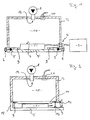
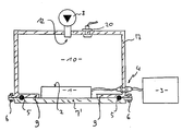
- a pressure chamber 10 is formed by a hood 7 which sits on a bottom surface 7 'and is sealed off from it by means of seals 5.
- a pressure sensor 20 which is connected to a display arrangement, not shown here. Furthermore, an inlet connector 12 is mounted in the hood 7, which is connected to a pump 8. Finally, a gas-tight plug connection 4 is provided in the hood 7, via which one can connect a sensor arrangement 1 introduced into the pressure chamber 10 to the associated evaluation device 3.
- Calibration is preferably carried out in such a way that the output signals of the sensor 20 are fed directly to the downstream evaluation device 3 and the calibration curves are stored in the evaluation device 3 as digital values which are used in subsequent current measurements to be offset against the measured values for their calibration.
- the arrangement according to FIG. 2 differs from that according to FIG. 1 in that the hood 7 is connected to the floor 7 'via an articulated connection 15 and can be held immovably to the floor 7' via a latching hook 14.
- the hood 7 has an inwardly projecting peripheral flange 9 to which a membrane 11 is tightly attached. If one wants to calibrate a sensor arrangement 1 with the aid of this device, one places the sensor arrangement 1 on the counter surface 13 formed by the base 7 'and pumps up the pressure chamber 10 via the pump 8. The membrane 1 then applies a uniform pressure to the sensor arrangement 1 without the entire sensor arrangement 1 having to be brought into the pressure space.
- the articulated connection 15 and the latching hook 14 are replaced by holding means 21 which comprise threaded bolts 22 which are fastened to the base 7 ′ and by bores in outwardly projecting flange edges the hood 7 (with play) protrude.
- holding means 21 comprise threaded bolts 22 which are fastened to the base 7 ′ and by bores in outwardly projecting flange edges the hood 7 (with play) protrude.
- nuts 23 and 24 are screwed onto the bolts 21 on both sides of the flange of the hood 7. This arrangement ensures that the hood 7 and thus also the membrane 11 attached to it can be held exactly above the counter surface 13 so that the membrane 11 runs essentially smoothly when the sensor arrangement 1 is inserted.
- the surface part of the membrane 11 that is not above the sensor arrangement is preferred 1 lies, filled with spacer elements 37 ', which have a thickness corresponding to the sensor arrangement 1. If the pressure chamber 10 is now pressurized, bulges of the membrane 11 can only occur in the remaining gaps, so that the membrane 11 can be made relatively thin and thus elastic.
- the device designed in this way can be set to different-sized sensor arrangements 1. If you want to calibrate a sensor arrangement 1 up to peak measured values of 250 N / cm2, a total force which is 930,000 N already occurs with an area of the membrane 11 of 30 cm ⁇ 40 cm. For this reason, it is advantageous to provide a large number of such holding devices 21.
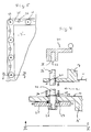
- the holding device 21 comprises a plurality of threaded bolts 21 which are fastened to the edge of the base 7 'so as to be rotatable but fixed in the longitudinal direction.
- This attachment takes place on the one hand by means of axial spherical roller bearings 27 and on the other hand by means of snap rings 28 which rest on the base 13 of the base 7 'via washers 29.
- the axial bearings 27 are arranged on the tension side, so that the high forces during calibration (when the pressure chamber is under pressure) are absorbed by these bearings.
- the threaded bolts 22 are seated in corresponding internal threads 31 in the outwardly projecting flange of the hood 7, the hood 7 being supported with respect to the base 7 ′ by springs 30. These springs 30 ensure that the frictional forces occurring when the bolts 22 are rotated are determined almost exclusively by the friction in the internal thread 31.
- the plurality of threaded bolts 25 each have clamped chain wheels 25 at their lower end (in FIG. 4), which are fixed on the threaded bolts 22 by nuts 26. About this chain wheels 25 runs a (single) chain 35 all around the edge of the bottom 7 ', which is held in engagement with the chain wheels 25 via deflection or tensioning chain wheels 36 becomes. If you now turn one of the threaded bolts 22, for example via a hand crank 34, which has a push-on opening 33 with a molded-on projection 32 corresponding to a step 32 'in the threaded bolt 22, this rotation is transmitted to all threaded bolts 22, so that the lifting and lowering of the bolts evenly Hood 7 relative to the floor 7 'is made possible.
- the holding means 21 comprise hydraulic cylinders which are fed by a common pressure source. This connection to a common pressure source ensures simultaneous actuation of the hydraulic cylinders, that is to say coupling all the pressure cylinders to one another.
- the evaluation device 3 is equipped with appropriate means (microprocessor) and with a valve between the pressure source 8 and the opening 12 in a controlling connection. Furthermore, the microprocessor of the evaluation device 3 is designed such that the valve is controlled so that the pressure generated in the pressure chamber 10 is adjusted in accordance with a calibration program.
- the pump 8 first generate a maximum pressure in the pressure chamber 10, then close the opening 12 (for example via a non-return valve) and via a valve (not shown) controlled by the evaluation device 3 the pressure in accordance with the desired Release calibration values into the atmosphere.
- calibration takes place both with increasing and also with falling pressure values, so that a (possibly present) hysteresis behavior of the sensors can be stored and taken into account in later measurements.
- the evaluation device 3 queries all sensors, accepts the instantaneous measured values as calibration values and stores them in the form of points in a characteristic field. Then the pressure is brought to the next calibration value.
Description
Die Erfindung betrifft ein Verfahren nach dem Oberbegriff des Patentanspruches 1 sowie eine Vorrichtung nach dem Oberbegriff des Anspruches 6.The invention relates to a method according to the preamble of claim 1 and a device according to the preamble of
Aus der DE-PS 25 29 475 und aus der DE-OS 30 11 266 sind Druckmeßaufnehmer für die Messung flächenhafter Druckverteilungen bekannt, also Meßvorrichtungen, bei denen eine Vielzahl von Meßpunkten, die in einer Ebene liegen, erfaßt werden. Den Sensoren sind hierbei Auswerteinrichtungen nachgeschaltet.From DE-PS 25 29 475 and from DE-OS 30 11 266 pressure transducers for measuring areal pressure distributions are known, ie measuring devices in which a multiplicity of measuring points lying in one plane are detected. Evaluation devices are connected downstream of the sensors.
Um die bekannten Meßaufnehmeranordnungen zu kalibrieren, hat man bisher jeden Einzelsensor mit einer konstanten Last (Gewicht) belastet und aus dem Differenzergebnis zwischen den Ausgangssignalen mit und ohne Last den Proportionalitätsfaktor, sowie gegebenenfalls die Lage des Nullpunktes des Sensors bestimmt. Dieses Verfahren ist zeitraubend, umständlich und führt trotz sorgfältiger Durchführung zu fehlerhaften Kalibrierungen.In order to calibrate the known sensor arrangements, each individual sensor has so far been loaded with a constant load (weight) and the proportionality factor and, if appropriate, the position of the zero point of the sensor have been determined from the difference between the output signals with and without load. This procedure is time-consuming, cumbersome and leads to incorrect calibrations despite careful implementation.
Ausgehend vom oben genannten Stand der Technik ist es Aufgabe der vorliegenden Erfindung, ein Verfahren der eingangs genannten Art dahingehend weiterzubilden, daß auf einfache Weise eine exakte Kalibrierung durchführbar ist.Starting from the above-mentioned prior art, it is an object of the present invention to develop a method of the type mentioned at the outset such that an exact calibration can be carried out in a simple manner.
Diese Aufgabe wird dadurch gelöst, daß man die Ausgangssignale bzw. Ausgangsamplituden aller Sensoren in unbelastetem Zustand mißt und aufzeichnet, die gesamte Meßaufnehmeranordnung mindestens teilweise in ein fluides Medium (Luft, Flüssigkeit) bringt, dessen Druck über dem Atmosphärendruck liegt und die Ausgangssignale der Sensoren sowie den Druck des fluiden Mediums mißt und aufzeichnet, die Proportionalitätsfaktoren und Nullpunkte aller Sensoren aus den Meßdaten bestimmt und in der Auswerteinrichtung speichert, und bei allen folgenden Messungen die Sensorausgangssignale nach Verschiebung um die gemessenen Nullpunktwerte mit dem betreffenden gespeicherten Proportionalitätsfaktor multipliziert. Wenn man das Verfahren in dieser Art durchführt, so gelangt man erstaunlicherweise zu wesentlich exakteren Kalibrierergebnissen, als dies bisher der Fall war. Dies rührt anscheinend insbesondere daher, daß bei der diskreten Kalibrierung aller Einzelsensoren die mechanische (zwangsläufig vorhandende) Kopplung zwischen den Sensoren das Meßergebnis verfälscht. Da andererseits bei aktuellen Messungen die Einzelsensoren zwar ungleichmäßig belastet werden, andererseits aber nebeneinaner liegende Sensoren aufgrund der normalerweise auftretenden "weichen" Übergänge der Kraft oder Druckverteilung mit ähnlichen Werten beaufschlagt sind. Dadurch hat die mechanische Kopplung zwischen den Einzelsensoren bei der aktuellen Messung einen geringeren Einfluß als bei der diskreten Kalibrierung, so daß das erfindungsgemäße Verfahren die Meßaufnehmeranordnung in einer Art und Weise belastet, die der aktuellen Messung wesentlich ähnlicher ist.This object is achieved by measuring and recording the output signals or output amplitudes of all sensors in the unloaded state, at least partially bringing the entire sensor arrangement into a fluid medium (air, liquid), the pressure of which is above atmospheric pressure and the output signals of the sensors as well measures and records the pressure of the fluid medium, determines the proportionality factors and zero points of all sensors from the measurement data and stores them in the evaluation device, and in all subsequent measurements multiplies the sensor output signals after being shifted by the measured zero point values by the relevant stored proportionality factor. If you carry out the method in this way, you will surprisingly get much more precise calibration results than was previously the case. This appears to be due in particular to the fact that the mechanical (inevitable) coupling between the sensors falsifies the measurement result in the discrete calibration of all individual sensors. On the other hand, since the individual sensors are loaded unevenly in current measurements, they are also juxtaposed lying sensors are exposed to similar values due to the normally occurring "soft" transitions in force or pressure distribution. As a result, the mechanical coupling between the individual sensors has less of an influence in the current measurement than in the discrete calibration, so that the method according to the invention loads the sensor arrangement in a manner which is much more similar to the current measurement.
Bei einer bevorzugten Ausführungsform des erfindungsgemäßen Verfahrens schließt man die Meßaufnehmeranordnung gegenüber dem fluiden Medium mit einer Schutzhülle ab. Die Schutzhülle verfälscht die vom fluiden Medium auf die Meßaufnehmeranordnung aufgebrachte Kraft praktisch nicht gewährleistet aber, daß man die Zuleitungskabel zur Meßaufnehmeranordnung ohne Abdichtmittel mit der nachgeschalteten Auswerteinrichtung verbinden kann. Besonders einfach wird das Verfahren dann, wenn man die Schutzhülle mit darüber liegendem fluidem Medium auf der einen Seite der Meßaufnehmeranordnung vorsieht und die Meßaufnehmeranordnung auf der anderen Seite ganzflächig abstützt.In a preferred embodiment of the method according to the invention, the sensor arrangement is sealed off from the fluid medium with a protective cover. The protective cover falsifies the force applied by the fluid medium to the sensor arrangement practically not guarantees, however, that the supply cable to the sensor arrangement can be connected to the downstream evaluation device without sealing means. The method becomes particularly simple when the protective cover with the fluid medium lying thereon is provided on one side of the sensor arrangement and the sensor arrangement is supported over the entire surface on the other side.
Zur Durchführung des Verfahrens eignet sich eine Vorrichtung, die einen Druckraum aufweist, der gegenüber der Atmosphäre dicht abschließbar und mit einer Befüllungsöffnung und einem Druckmeßfühler versehen ist. Die Befüllungsöffnung wird mit einer Pumpe verbunden, die gegebenenfalls auch fest auf dem Druckraum installiert sein kann.Suitable for carrying out the method is a device which has a pressure chamber which can be sealed off from the atmosphere and is provided with a filling opening and a pressure sensor. The filling opening is connected to a pump, which may also be installed permanently on the pressure chamber.
Bei einer bevorzugten Ausführungsform der Erfindung ist der Druckraum auf einer Seite durch eine Membran abgeschlossen und gegenüber einer Grundfläche fixierbar.In a preferred embodiment of the invention, the pressure space is closed on one side by a membrane and can be fixed relative to a base area.
Weitere erfindungswesentliche Merkmale ergeben sich aus der nachfolgenden Beschreibung von Ausführungsbeispielen, die anhand von Abbildungen näher erläutert sind. Hierbei zeigen:
- Fig. 1
- eine erste bevorzugte Ausführungsform einer Vorrichtung zur Durchführung des Kalibrierverfahrens;
- Fig. 2
- eine zweite bevorzugte Ausführungsform der Vorrichtung.
- Fig. 3
- eine weitere bevorzugte Ausführungsform der Erfindung in einer Ansicht ähnlich der nach Fig. 2;
- Fig. 4
- eine Detailansicht einer bevorzugten Ausführungsform der in Fig. 3 angedeuteten Haltemittel im Längsschnitt; und
- Fig. 5
- einen Schnitt entlang der Linie V-V aus Fig. 4.
- Fig. 1
- a first preferred embodiment of a device for performing the calibration method;
- Fig. 2
- a second preferred embodiment of the device.
- Fig. 3
- a further preferred embodiment of the invention in a view similar to that of FIG. 2;
- Fig. 4
- a detailed view of a preferred embodiment of the holding means indicated in Figure 3 in longitudinal section. and
- Fig. 5
- 3 shows a section along the line VV from FIG. 4.
Bei der in Fig. 1 gezeigten Vorrichtung wird ein Druckraum 10 von einer Haube 7 gebildet, die auf einer Bodenfläche 7' sitzt und gegenüber dieser mittels Dichtungen 5 abgedichtet ist. Die Haube 7 und der Boden 7' werden über Spannschrauben 6 zusammengehalten.In the device shown in FIG. 1, a
In der Haube 7 befindet sich ein Druckmeßfühler 20, der mit einer hier nicht gezeigten Anzeigeanordnung verbunden ist. Weiterhin ist in der Haube 7 ein Einlaßstutzen 12 montiert, der mit einer Pumpe 8 in Verbindung steht. Schließlich ist in der Haube 7 eine gasdichte Steckerverbindung 4 vorgesehen, über die man eine in den Druckraum 10 eingebrachte Meßaufnehmeranordnung 1 mit der dazugehörigen Auswerteinrichtung 3 verbinden kann.In the
Vorzugsweise geht man beim Kalibrieren derart vor, daß man die Ausgangssignale des Meßaufnehmers 20 direkt der nachgeschalteten Auswerteinrichtung 3 zuführt und die Kalibrierkurven in der Auswerteinrichtung 3 als Digitalwerte speichert, welche bei nachfolgenden akutellen Messungen mit den Meßwerten zu deren Kalibrierung verrechnet werden.Calibration is preferably carried out in such a way that the output signals of the
Die Anordnung nach Fig. 2 unterscheidet sich von der nach Fig. 1 insofern, als die Haube 7 mit dem Boden 7' über eine Gelenkverbindung 15 verbunden ist und zum Boden 7' über einen Rasthaken 14 unbeweglich gehalten werden kann. Die Haube 7 weist einen nach innen ragenden Umfangsflansch 9 auf, an dem eine Membran 11 dicht befestigt ist. Will man eine Meßaufnehmeranordnung 1 mit Hilfe dieser Vorrichtung kalibrieren, so legt man die Meßaufnehmeranordnung 1 auf die vom Boden 7' gebildete Gegenfläche 13 und pumpt den Druckraum 10 über die Pumpe 8 auf. Die Membran 1 beaufschlagt dann die Meßaufnehmeranordnung 1 mit einem gleichmäßigen Druck, ohne daß dabei die ganze Meßaufnehmeranordnung 1 in den Druckraum gebracht werden muß.The arrangement according to FIG. 2 differs from that according to FIG. 1 in that the
Bei einer weiteren bevorzugten Ausführungsform, die in Fig. 3 gezeigt ist, sind die Gelenkverbindung 15 und der Rasthaken 14 durch Haltemittel 21 ersetzt, die Gewindebolzen 22 umfassen, welche an dem Boden 7' befestigt sind und durch Bohrungen in nach außen ragenden Flansch-Rändern der Haube 7 (mit Spiel) ragen. Um die Haube 7 gegenüber dem Boden 13 in einem definierten Abstand zu halten, sind auf beiden Seiten des Flansches der Haube 7 Muttern 23 bzw. 24 auf die Bolzen 21 aufgeschraubt. Durch diese Anordnung ist gewährleistet, daß man die Haube 7 und damit auch die an ihr befestigte Membran 11 exakt so hoch über der Gegenfläche 13 halten kann, daß die Membran 11 bei eingeschobener Meßaufnehmeranordnung 1 im wesentlichen glatt verläuft. Weiterhin wird vorzugsweise der Flächenteil der Membran 11, der nicht über der Meßaufnehmeranordnung 1 liegt, mit Distanzelementen 37' ausgefüllt, die eine der Meßaufnehmeranordnung 1 entsprechende Dicke haben. Wenn nun der Druckraum 10 unter Druck gesetzt wird, so können nur an den verbleibenden Spalten Ausbeulungen der Membran 11 auftreten, so daß diese relativ dünn und damit elastisch ausgebildet werden kann. Darüber hinaus ist die so ausgebildete Vorrichtung auf verschieden dicke Meßaufnehmeranordnungen 1 einstellbar. Wenn man eine Meßaufnehmeranordnung 1 bis zu Spitzen-Meßwerten von 250 N/cm² kalibrieren will, so tritt bereits bei einer Fläche der Membran 11 von 30 cm x 40 cm eine Gesamtkraft auf, die bei 930.000 N liegt. Aus diesem Grunde ist es von Vorteil, wenn man eine große Vielzahl derartiger Haltevorrichtungen 21 vorsieht.In a further preferred embodiment, which is shown in FIG. 3, the articulated
Bei einer bevorzugten Ausführungsform, die in den Fig. 4 und 5 schematisiert dargestellt ist, umfaßt die Haltevorrichtung 21 eine Vielzahl von Gewindebolzen 21, die am Rand des Bodens 7' drehbar aber in Längsrichtung fixiert befestigt sind. Diese Befestigung geschieht einerseits durch Axial-Pendelrollenlager 27, andererseits durch Sprengringe 28, die über Beilegscheiben 29 auf der Grundfläche 13 des Bodens 7' aufliegen. Die Axiallager 27 sind hierbei zug-seitig angeordnet, so daß die hohen Kräfte beim Kalibrieren (wenn der Druckraum unter Druck steht) über diese Lager aufgefangen werden. Die Gewindebolzen 22 sitzen in entsprechenden Innengewinden 31 im nach außen ragenden Flansch der Haube 7, wobei die Haube 7 gegenüber dem Boden 7' über Federn 30 abgestützt wird. Durch diese Federn 30 ist gewährleistet, daß die beim Drehen der Bolzen 22 auftretenden Reibungskräfte fast ausschließlich durch die Reibung im Innengewinde 31 bestimmt werden.In a preferred embodiment, which is shown schematically in FIGS. 4 and 5, the
Die Vielzahl von Gewindebolzen 25 weisen an ihrem unteren Ende (in Fig. 4) jeweils aufgespannte Kettenräder 25 auf, die auf den Gewindebolzen 22 über Muttern 26 festgesetzt sind. Über diese Kettenräder 25 läuft eine (einzige) Kette 35 ringsum den Rand des Bodens 7', die über Umlenk- oder Spann-Kettenräder 36 mit den Kettenrädern 25 in Eingriff gehalten wird. Dreht man nun einen der Gewindebolzen 22, z.B. über eine Handkurbel 34, die eine Aufstecköffnung 33 mit angeformtem Ansatz 32 entsprechend einem Einschitt 32' im Gewindebolzen 22 aufweist, so wird diese Drehung auf alle Gewindebolzen 22 übertragen, so daß ein gleichmäßiges Heben und Senken der Haube 7 gegenüber dem Boden 7' ermöglicht wird. Hierdurch ist es möglich, eine besonders leichte und zusätzlich auch besonders gleichmäßige Verspannung zwischen der Haube 7 und dem Boden 7' zu erzielen, was in Anbetracht der auftretenden hohen Kräfte besonders wichtig ist. Statt einer Handkurbel 34 sind selbstverständlich auch motorische Antriebsmittel für die Kette 35 möglich.The plurality of threaded
Bei einer anderen, hier nicht gezeigten bevorzugten Ausführungsform der Erfindung umfassen die Haltemittel 21 Hydraulikzylinder, die von einer gemeinsamen Druckquelle gespeist werden. Durch diese Verbindung mit einer gemeinsamen Druckquelle ist eine gleichzeitige Betätigung der Hydraulikzylinder, also eine Kopplung aller Druckzylinder untereinander sichergestellt.In another preferred embodiment of the invention, not shown here, the holding means 21 comprise hydraulic cylinders which are fed by a common pressure source. This connection to a common pressure source ensures simultaneous actuation of the hydraulic cylinders, that is to say coupling all the pressure cylinders to one another.
Bei einer hier nicht gezeigten weiteren bevorzugten Ausführungsform der Erfindung ist die Auswerteinrichtung 3 mit entsprechenden Mitteln (Mikroprozessor) ausgestattet und mit einem Ventil zwischen der Druckquelle 8 und der Öffnung 12 in steuernder Verbindung. Weiterhin ist der Mikroprozessor der Auswerteinrichtung 3 derart ausgebildet, daß das Ventil so gesteuert wird, daß der im Druckraum 10 erzeugte Druck entsprechend einem Eichprogramm eingestellt wird. Selbstverständlich ist es auch möglich, die Pumpe 8 zunächst einen Maximaldruck im Druckraum 10 erzeugen zu lassen, dann die Öffnung 12 (z.B. über ein Rückschlagventil) zu schließen und über ein (nicht gezeigtes), von der Auswerteinrichtung 3 gesteuertes Ventil den Druck entsprechend den gewünschten Kalibrierwerten in die Atmosphäre abzulassen.In a further preferred embodiment of the invention, not shown here, the
Bei einer besonders bevorzugten Ausführungsform der Erfindung erfolgt eine Eichung sowohl mit steigenden, als auch zusätzlich mit fallenden Druckwerten, so daß ein (gegebenenfalls vorliegendes) Hystereseverhalten der Sensoren gespeichert und bei späteren Messungen berücksichtigt werden kann. Weiterhin ist es besonders bevorzugt, den von der Druckquelle 8 erzeugten Druck mit einem Druckfühler abzutasten und der Auswerteinrichtung 3 mitzuteilen, so daß die Auswerteinrichtung 3 entweder ein Magnetventil zur Konstanthaltung definierter Druckwerte steuern oder bei Erreichen eines definierten Druckwertes den Eichvorgang sampeln kann. Bei Erreichen dieses bestimmten Druckwertes fragt dann die Auswerteinrichtung 3 alle Sensoren ab, übernimmt die momentanen Meßwerte als Eichwerte und speichert sie in Form von Punkten eines Kennlinienfeldes ab. Danach wird der Druck auf den nächsten Eichwert gebracht.In a particularly preferred embodiment of the invention, calibration takes place both with increasing and also with falling pressure values, so that a (possibly present) hysteresis behavior of the sensors can be stored and taken into account in later measurements. Furthermore, it is particularly preferred to sense the pressure generated by the
Bei allen vorgenannten Ausführungsformen der Erfindung ist es also wesentlich, daß die erzeugten Kraftwerte von der Auswerteinrichtung 3 gesteuert werden.In all of the aforementioned embodiments of the invention, it is therefore essential that the force values generated are controlled by the
Claims (10)
- A calibration process for a sensor arrangement with a following analysis device for measuring the force/pressure distribution over a surface provided with sensors, e.g. individual sensors,
characterised in that
the output signals and amplitudes of all the sensors are measured and recorded in the unloaded state,
the entire sensor arrangement is at least partially introduced into a fluid medium, e.g. air, liquid, the pressure of which is greater than the atmospheric pressure, and that the output signals of the sensors and the pressure of the fluid medium are measured and recorded,
the proportionality factors and zero points of all the sensors are determined from the measurement data and stored in the analysis device and that
in the case of all the following measurements the sensor output signals, having been displaced by the measured zero point values, are multiplied by the respective, stored proportionality factors. - A calibration process as claimed in Claim 1, characterised in that the pressure above the atmospheric pressure is controlled by the analysis device.
- A calibration process as claimed in Claim 2, characterised in that the pressure above the atmospheric pressure is monitored via a sensor by the analysis device.
- A device for the implementation of a calibration process for a sensor arrangement with an analysis device connected to the output end of the sensor arrangement for measuring the force/pressure distribution over a surface provided with sensors, e.g. individual sensors, characterised in that a pressure chamber (10) is provided which can be tightly sealed in relation to the atmosphere and is provided with a filling opening (12) and a pressure sensor (20) and is constructed in such manner that the sensor arrangement (1) can be acted upon by the pressure in the pressure chamber (10), and that the analysis device comprises storage devices in order to store proportionality factors and zero points of all the sensors and to take these into consideration in following measurements.
- A device as claimed in Claim 4, characterised in that the pressure chamber (10) is sealed by a membrane (11) on one side and can be fixed in relation to a surface (13) of a base (7').
- A device as claimed in Claim 5, characterised in that the pressure chamber (10) is constructed in a dome (7) which on one side is sealed by the membrane (11) and on this side can be fixed at a predeterminable distance in relation to the base (7') via adjustable retention means.
- A device as claimed in Claim 6, characterised in that a plurality of retention means (21) are provided between the dome (7) and the base (7') for the distribution of the occurring forces, which retention means are coupled to one another via connecting means (25, 35) for simultaneous adjustment.
- A device as claimed in one of Claims 4 to 7, characterised in that the storage devices in the analysis device (3) are designed such that characteristic curves of all the sensors can be stored and can be called up for the linearisation of actual sensor output signals.
- A device as claimed in one of Claims 4 to 8, characterised in that the analysis device (3) is designed and connected to the pressure sensor (20) in such manner that the output values of the sensor arrangement are automatically allocated to the measured pressure values by the analysis device (3).
- A device as claimed in one of Claims 4 to 9, characterised in that the analysis device (3) is connected in controlling fashion to a remote-adjustable valve which is arranged between the filling opening (12) and a pressure source, and that the analysis device (3) is designed in such manner that the pressure in the pressure chamber (10) can be automatically adjusted via the valve.
Applications Claiming Priority (2)
| Application Number | Priority Date | Filing Date | Title |
|---|---|---|---|
| DE3725471 | 1987-07-31 | ||
| DE3725471 | 1987-07-31 |
Publications (3)
| Publication Number | Publication Date |
|---|---|
| EP0302385A2 EP0302385A2 (en) | 1989-02-08 |
| EP0302385A3 EP0302385A3 (en) | 1990-12-05 |
| EP0302385B1 true EP0302385B1 (en) | 1993-03-17 |
Family
ID=6332830
Family Applications (1)
| Application Number | Title | Priority Date | Filing Date |
|---|---|---|---|
| EP88112171A Expired - Lifetime EP0302385B1 (en) | 1987-07-31 | 1988-07-27 | Device and process for calibrating force distribution sensors |
Country Status (2)
| Country | Link |
|---|---|
| EP (1) | EP0302385B1 (en) |
| DE (1) | DE3879312D1 (en) |
Families Citing this family (9)
| Publication number | Priority date | Publication date | Assignee | Title |
|---|---|---|---|---|
| US4860587A (en) * | 1988-05-31 | 1989-08-29 | Keller Carl E | Stress gauge |
| FR2656096B1 (en) * | 1989-12-15 | 1992-04-17 | Clecim Sa | SENSOR CALIBRATION DEVICE. |
| US5440237A (en) * | 1993-06-01 | 1995-08-08 | Incontrol Solutions, Inc. | Electronic force sensing with sensor normalization |
| FR2725519B1 (en) * | 1994-10-10 | 1996-12-13 | Ainf Sa | METHOD AND DEVICE FOR TESTING THE INTEGRITY OF A DEFORMATION SENSOR |
| DE10119600A1 (en) * | 2001-04-21 | 2002-10-31 | Bosch Gmbh Robert | Device and method for calibrating a sensor |
| EP3657147A1 (en) | 2018-11-21 | 2020-05-27 | Bayer AG | Calibration device for calibrating a pressure measuring device and corresponding use to this calibration device |
| CN113310624A (en) * | 2021-06-24 | 2021-08-27 | 吉林大学 | Parking braking force sensor calibrating device |
| CN113654720B (en) * | 2021-09-02 | 2023-11-17 | 安徽中科本元信息科技有限公司 | Pneumatic flexible force sensor calibration device and calibration method |
| CN115389099A (en) * | 2022-10-26 | 2022-11-25 | 北京中科富海低温科技有限公司 | Pressure sensor calibration device |
Family Cites Families (2)
| Publication number | Priority date | Publication date | Assignee | Title |
|---|---|---|---|---|
| DE1473497A1 (en) * | 1964-10-21 | 1969-05-08 | Kistler Instrumente Ag | Pressure measuring device |
| FR2608760B1 (en) * | 1986-05-14 | 1989-03-10 | Lorraine Laminage | METHOD AND DEVICE FOR CONTROLLED ACTUATION OF CONSTRAINT SENSORS FOR THEIR CALIBRATION |
-
1988
- 1988-07-27 DE DE8888112171T patent/DE3879312D1/en not_active Expired - Fee Related
- 1988-07-27 EP EP88112171A patent/EP0302385B1/en not_active Expired - Lifetime
Also Published As
| Publication number | Publication date |
|---|---|
| DE3879312D1 (en) | 1993-04-22 |
| EP0302385A3 (en) | 1990-12-05 |
| EP0302385A2 (en) | 1989-02-08 |
Similar Documents
| Publication | Publication Date | Title |
|---|---|---|
| DE3447008C2 (en) | Sealing device for a gate valve | |
| DE3620391C2 (en) | ||
| DE2839180C2 (en) | ||
| EP0302385B1 (en) | Device and process for calibrating force distribution sensors | |
| DE3822486A1 (en) | DEVICE FOR MEASURING THE TENSION OF A GOODS | |
| DE2855582A1 (en) | PRESSURE SWITCH | |
| DE3111434C2 (en) | Device for measuring the axial force in a shaft supported by roller bearings | |
| DE2443158C2 (en) | Method and device for determining the shear stress in powdery and / or granular material | |
| DE19755244C1 (en) | Flange connection mechanism especially for chromatography column | |
| DE3238951C2 (en) | Force transducers | |
| DE3341721C2 (en) | Testing device for vehicle wheels | |
| EP0338325A1 (en) | Ring-shaped torsion-type force measuring device | |
| EP0179278A2 (en) | Pressure sensor | |
| EP3276310B1 (en) | Length measuring device | |
| EP0045355B1 (en) | Device for measuring the initial tension of two cylinders put one against the other | |
| EP3252451A1 (en) | Method for testing resistance | |
| DE3803041A1 (en) | DEVICE FOR PRESSURE DISPLAY | |
| DE3513991C1 (en) | Measuring arrangement for measuring clamping forces in anchor cables | |
| DE102019207127A1 (en) | Application unit with pressure force measurement | |
| DE3814646C2 (en) | Device for checking motor vehicle tires | |
| DE102017130769A1 (en) | measuring roller | |
| DE102018110482A1 (en) | Method for screwing a bolt system, bolt system and bolt tensioning device | |
| EP1212564B1 (en) | Device for checking a safety valve | |
| EP0069280A1 (en) | Indicator device for vehicle brakes, especially disc brakes of railway vehicles | |
| DE1478850C3 (en) | Manipulating device |
Legal Events
| Date | Code | Title | Description |
|---|---|---|---|
| PUAI | Public reference made under article 153(3) epc to a published international application that has entered the european phase |
Free format text: ORIGINAL CODE: 0009012 |
|
| AK | Designated contracting states |
Kind code of ref document: A2 Designated state(s): BE CH DE FR GB IT LI |
|
| PUAL | Search report despatched |
Free format text: ORIGINAL CODE: 0009013 |
|
| AK | Designated contracting states |
Kind code of ref document: A3 Designated state(s): BE CH DE FR GB IT LI |
|
| 17P | Request for examination filed |
Effective date: 19901217 |
|
| 17Q | First examination report despatched |
Effective date: 19910730 |
|
| GRAA | (expected) grant |
Free format text: ORIGINAL CODE: 0009210 |
|
| AK | Designated contracting states |
Kind code of ref document: B1 Designated state(s): BE CH DE FR GB IT LI |
|
| PG25 | Lapsed in a contracting state [announced via postgrant information from national office to epo] |
Ref country code: IT Free format text: LAPSE BECAUSE OF FAILURE TO SUBMIT A TRANSLATION OF THE DESCRIPTION OR TO PAY THE FEE WITHIN THE PRE;WARNING: LAPSES OF ITALIAN PATENTS WITH EFFECTIVE DATE BEFORE 2007 MAY HAVE OCCURRED AT ANY TIME BEFORE 2007. THE CORRECT EFFECTIVE DATE MAY BE DIFFERENT FROM THE ONE RECORDED.SCRIBED TIME-LIMIT Effective date: 19930317 Ref country code: BE Effective date: 19930317 |
|
| ET | Fr: translation filed | ||
| REF | Corresponds to: |
Ref document number: 3879312 Country of ref document: DE Date of ref document: 19930422 |
|
| GBT | Gb: translation of ep patent filed (gb section 77(6)(a)/1977) |
Effective date: 19930406 |
|
| PG25 | Lapsed in a contracting state [announced via postgrant information from national office to epo] |
Ref country code: LI Effective date: 19930731 Ref country code: CH Effective date: 19930731 |
|
| PLBE | No opposition filed within time limit |
Free format text: ORIGINAL CODE: 0009261 |
|
| STAA | Information on the status of an ep patent application or granted ep patent |
Free format text: STATUS: NO OPPOSITION FILED WITHIN TIME LIMIT |
|
| 26N | No opposition filed | ||
| REG | Reference to a national code |
Ref country code: CH Ref legal event code: PL |
|
| REG | Reference to a national code |
Ref country code: CH Ref legal event code: AUV Free format text: DAS OBENGENANNTE PATENT IST, MANGELS BEZAHLUNG DER 6. JAHRESGEBUEHR GELOESCHT WORDEN. |
|
| REG | Reference to a national code |
Ref country code: GB Ref legal event code: IF02 |
|
| PGFP | Annual fee paid to national office [announced via postgrant information from national office to epo] |
Ref country code: GB Payment date: 20040713 Year of fee payment: 17 |
|
| PGFP | Annual fee paid to national office [announced via postgrant information from national office to epo] |
Ref country code: FR Payment date: 20040720 Year of fee payment: 17 |
|
| PGFP | Annual fee paid to national office [announced via postgrant information from national office to epo] |
Ref country code: DE Payment date: 20040927 Year of fee payment: 17 |
|
| PG25 | Lapsed in a contracting state [announced via postgrant information from national office to epo] |
Ref country code: GB Free format text: LAPSE BECAUSE OF NON-PAYMENT OF DUE FEES Effective date: 20050727 |
|
| PG25 | Lapsed in a contracting state [announced via postgrant information from national office to epo] |
Ref country code: DE Free format text: LAPSE BECAUSE OF NON-PAYMENT OF DUE FEES Effective date: 20060201 |
|
| GBPC | Gb: european patent ceased through non-payment of renewal fee |
Effective date: 20050727 |
|
| PG25 | Lapsed in a contracting state [announced via postgrant information from national office to epo] |
Ref country code: FR Free format text: LAPSE BECAUSE OF NON-PAYMENT OF DUE FEES Effective date: 20060331 |
|
| REG | Reference to a national code |
Ref country code: FR Ref legal event code: ST Effective date: 20060331 |