EP0301514A2 - Verfahren und Apparat zur Erzeugung von ultrareinem Sauerstoff bei Flüssigbeschickung - Google Patents
Verfahren und Apparat zur Erzeugung von ultrareinem Sauerstoff bei Flüssigbeschickung Download PDFInfo
- Publication number
- EP0301514A2 EP0301514A2 EP88112153A EP88112153A EP0301514A2 EP 0301514 A2 EP0301514 A2 EP 0301514A2 EP 88112153 A EP88112153 A EP 88112153A EP 88112153 A EP88112153 A EP 88112153A EP 0301514 A2 EP0301514 A2 EP 0301514A2
- Authority
- EP
- European Patent Office
- Prior art keywords
- liquid
- vapor
- column
- high purity
- ultra high
- Prior art date
- Legal status (The legal status is an assumption and is not a legal conclusion. Google has not performed a legal analysis and makes no representation as to the accuracy of the status listed.)
- Granted
Links
- QVGXLLKOCUKJST-UHFFFAOYSA-N atomic oxygen Chemical compound [O] QVGXLLKOCUKJST-UHFFFAOYSA-N 0.000 title claims abstract description 65
- 239000001301 oxygen Substances 0.000 title claims abstract description 65
- 229910052760 oxygen Inorganic materials 0.000 title claims abstract description 65
- 238000000034 method Methods 0.000 title claims abstract description 23
- 239000007788 liquid Substances 0.000 title claims description 80
- 239000012535 impurity Substances 0.000 claims description 41
- XKRFYHLGVUSROY-UHFFFAOYSA-N Argon Chemical compound [Ar] XKRFYHLGVUSROY-UHFFFAOYSA-N 0.000 claims description 28
- VNWKTOKETHGBQD-UHFFFAOYSA-N methane Chemical compound C VNWKTOKETHGBQD-UHFFFAOYSA-N 0.000 claims description 26
- 239000012530 fluid Substances 0.000 claims description 25
- 238000000926 separation method Methods 0.000 claims description 21
- 230000008016 vaporization Effects 0.000 claims description 20
- 229910052786 argon Inorganic materials 0.000 claims description 14
- 239000007789 gas Substances 0.000 claims description 9
- 238000009833 condensation Methods 0.000 claims description 6
- 230000005494 condensation Effects 0.000 claims description 6
- 239000007791 liquid phase Substances 0.000 claims description 6
- 239000012071 phase Substances 0.000 claims description 6
- YBJHBAHKTGYVGT-ZKWXMUAHSA-N (+)-Biotin Chemical compound N1C(=O)N[C@@H]2[C@H](CCCCC(=O)O)SC[C@@H]21 YBJHBAHKTGYVGT-ZKWXMUAHSA-N 0.000 claims description 3
- 230000001174 ascending effect Effects 0.000 claims description 3
- FEPMHVLSLDOMQC-UHFFFAOYSA-N virginiamycin-S1 Natural products CC1OC(=O)C(C=2C=CC=CC=2)NC(=O)C2CC(=O)CCN2C(=O)C(CC=2C=CC=CC=2)N(C)C(=O)C2CCCN2C(=O)C(CC)NC(=O)C1NC(=O)C1=NC=CC=C1O FEPMHVLSLDOMQC-UHFFFAOYSA-N 0.000 claims description 3
- 238000009834 vaporization Methods 0.000 claims 3
- MYMOFIZGZYHOMD-UHFFFAOYSA-N Dioxygen Chemical compound O=O MYMOFIZGZYHOMD-UHFFFAOYSA-N 0.000 claims 1
- 238000012856 packing Methods 0.000 description 5
- 238000007084 catalytic combustion reaction Methods 0.000 description 4
- 238000004821 distillation Methods 0.000 description 4
- 238000004519 manufacturing process Methods 0.000 description 4
- 239000011555 saturated liquid Substances 0.000 description 3
- IJGRMHOSHXDMSA-UHFFFAOYSA-N Atomic nitrogen Chemical compound N#N IJGRMHOSHXDMSA-UHFFFAOYSA-N 0.000 description 2
- 230000006835 compression Effects 0.000 description 2
- 238000007906 compression Methods 0.000 description 2
- 238000005094 computer simulation Methods 0.000 description 2
- 238000010586 diagram Methods 0.000 description 2
- 230000000694 effects Effects 0.000 description 2
- 238000004508 fractional distillation Methods 0.000 description 2
- 229920006395 saturated elastomer Polymers 0.000 description 2
- 241000894007 species Species 0.000 description 2
- 239000012808 vapor phase Substances 0.000 description 2
- UFHFLCQGNIYNRP-UHFFFAOYSA-N Hydrogen Chemical compound [H][H] UFHFLCQGNIYNRP-UHFFFAOYSA-N 0.000 description 1
- AXGTXDWPVWSEOX-UHFFFAOYSA-N argon methane Chemical compound [Ar].[H]C[H].[H]C[H] AXGTXDWPVWSEOX-UHFFFAOYSA-N 0.000 description 1
- 239000003054 catalyst Substances 0.000 description 1
- 238000001944 continuous distillation Methods 0.000 description 1
- 238000005194 fractionation Methods 0.000 description 1
- 239000001307 helium Substances 0.000 description 1
- 229910052734 helium Inorganic materials 0.000 description 1
- SWQJXJOGLNCZEY-UHFFFAOYSA-N helium atom Chemical compound [He] SWQJXJOGLNCZEY-UHFFFAOYSA-N 0.000 description 1
- 229930195733 hydrocarbon Natural products 0.000 description 1
- 150000002430 hydrocarbons Chemical class 0.000 description 1
- 239000001257 hydrogen Substances 0.000 description 1
- 229910052739 hydrogen Inorganic materials 0.000 description 1
- 229910052743 krypton Inorganic materials 0.000 description 1
- DNNSSWSSYDEUBZ-UHFFFAOYSA-N krypton atom Chemical compound [Kr] DNNSSWSSYDEUBZ-UHFFFAOYSA-N 0.000 description 1
- 239000000203 mixture Substances 0.000 description 1
- 229910052757 nitrogen Inorganic materials 0.000 description 1
- 238000005057 refrigeration Methods 0.000 description 1
- 239000000126 substance Substances 0.000 description 1
- 238000010792 warming Methods 0.000 description 1
- 229910052724 xenon Inorganic materials 0.000 description 1
- FHNFHKCVQCLJFQ-UHFFFAOYSA-N xenon atom Chemical compound [Xe] FHNFHKCVQCLJFQ-UHFFFAOYSA-N 0.000 description 1
Images

Classifications
-
- B—PERFORMING OPERATIONS; TRANSPORTING
- B01—PHYSICAL OR CHEMICAL PROCESSES OR APPARATUS IN GENERAL
- B01D—SEPARATION
- B01D53/00—Separation of gases or vapours; Recovering vapours of volatile solvents from gases; Chemical or biological purification of waste gases, e.g. engine exhaust gases, smoke, fumes, flue gases, aerosols
- B01D53/34—Chemical or biological purification of waste gases
- B01D53/46—Removing components of defined structure
- B01D53/64—Heavy metals or compounds thereof, e.g. mercury
-
- F—MECHANICAL ENGINEERING; LIGHTING; HEATING; WEAPONS; BLASTING
- F25—REFRIGERATION OR COOLING; COMBINED HEATING AND REFRIGERATION SYSTEMS; HEAT PUMP SYSTEMS; MANUFACTURE OR STORAGE OF ICE; LIQUEFACTION SOLIDIFICATION OF GASES
- F25J—LIQUEFACTION, SOLIDIFICATION OR SEPARATION OF GASES OR GASEOUS OR LIQUEFIED GASEOUS MIXTURES BY PRESSURE AND COLD TREATMENT OR BY BRINGING THEM INTO THE SUPERCRITICAL STATE
- F25J3/00—Processes or apparatus for separating the constituents of gaseous or liquefied gaseous mixtures involving the use of liquefaction or solidification
- F25J3/08—Separating gaseous impurities from gases or gaseous mixtures or from liquefied gases or liquefied gaseous mixtures
-
- B—PERFORMING OPERATIONS; TRANSPORTING
- B01—PHYSICAL OR CHEMICAL PROCESSES OR APPARATUS IN GENERAL
- B01D—SEPARATION
- B01D53/00—Separation of gases or vapours; Recovering vapours of volatile solvents from gases; Chemical or biological purification of waste gases, e.g. engine exhaust gases, smoke, fumes, flue gases, aerosols
- B01D53/02—Separation of gases or vapours; Recovering vapours of volatile solvents from gases; Chemical or biological purification of waste gases, e.g. engine exhaust gases, smoke, fumes, flue gases, aerosols by adsorption, e.g. preparative gas chromatography
- B01D53/04—Separation of gases or vapours; Recovering vapours of volatile solvents from gases; Chemical or biological purification of waste gases, e.g. engine exhaust gases, smoke, fumes, flue gases, aerosols by adsorption, e.g. preparative gas chromatography with stationary adsorbents
-
- F—MECHANICAL ENGINEERING; LIGHTING; HEATING; WEAPONS; BLASTING
- F25—REFRIGERATION OR COOLING; COMBINED HEATING AND REFRIGERATION SYSTEMS; HEAT PUMP SYSTEMS; MANUFACTURE OR STORAGE OF ICE; LIQUEFACTION SOLIDIFICATION OF GASES
- F25J—LIQUEFACTION, SOLIDIFICATION OR SEPARATION OF GASES OR GASEOUS OR LIQUEFIED GASEOUS MIXTURES BY PRESSURE AND COLD TREATMENT OR BY BRINGING THEM INTO THE SUPERCRITICAL STATE
- F25J2200/00—Processes or apparatus using separation by rectification
- F25J2200/02—Processes or apparatus using separation by rectification in a single pressure main column system
-
- F—MECHANICAL ENGINEERING; LIGHTING; HEATING; WEAPONS; BLASTING
- F25—REFRIGERATION OR COOLING; COMBINED HEATING AND REFRIGERATION SYSTEMS; HEAT PUMP SYSTEMS; MANUFACTURE OR STORAGE OF ICE; LIQUEFACTION SOLIDIFICATION OF GASES
- F25J—LIQUEFACTION, SOLIDIFICATION OR SEPARATION OF GASES OR GASEOUS OR LIQUEFIED GASEOUS MIXTURES BY PRESSURE AND COLD TREATMENT OR BY BRINGING THEM INTO THE SUPERCRITICAL STATE
- F25J2200/00—Processes or apparatus using separation by rectification
- F25J2200/30—Processes or apparatus using separation by rectification using a side column in a single pressure column system
-
- F—MECHANICAL ENGINEERING; LIGHTING; HEATING; WEAPONS; BLASTING
- F25—REFRIGERATION OR COOLING; COMBINED HEATING AND REFRIGERATION SYSTEMS; HEAT PUMP SYSTEMS; MANUFACTURE OR STORAGE OF ICE; LIQUEFACTION SOLIDIFICATION OF GASES
- F25J—LIQUEFACTION, SOLIDIFICATION OR SEPARATION OF GASES OR GASEOUS OR LIQUEFIED GASEOUS MIXTURES BY PRESSURE AND COLD TREATMENT OR BY BRINGING THEM INTO THE SUPERCRITICAL STATE
- F25J2210/00—Processes characterised by the type or other details of the feed stream
- F25J2210/50—Oxygen
-
- F—MECHANICAL ENGINEERING; LIGHTING; HEATING; WEAPONS; BLASTING
- F25—REFRIGERATION OR COOLING; COMBINED HEATING AND REFRIGERATION SYSTEMS; HEAT PUMP SYSTEMS; MANUFACTURE OR STORAGE OF ICE; LIQUEFACTION SOLIDIFICATION OF GASES
- F25J—LIQUEFACTION, SOLIDIFICATION OR SEPARATION OF GASES OR GASEOUS OR LIQUEFIED GASEOUS MIXTURES BY PRESSURE AND COLD TREATMENT OR BY BRINGING THEM INTO THE SUPERCRITICAL STATE
- F25J2215/00—Processes characterised by the type or other details of the product stream
- F25J2215/50—Oxygen or special cases, e.g. isotope-mixtures or low purity O2
- F25J2215/56—Ultra high purity oxygen, i.e. generally more than 99,9% O2
-
- F—MECHANICAL ENGINEERING; LIGHTING; HEATING; WEAPONS; BLASTING
- F25—REFRIGERATION OR COOLING; COMBINED HEATING AND REFRIGERATION SYSTEMS; HEAT PUMP SYSTEMS; MANUFACTURE OR STORAGE OF ICE; LIQUEFACTION SOLIDIFICATION OF GASES
- F25J—LIQUEFACTION, SOLIDIFICATION OR SEPARATION OF GASES OR GASEOUS OR LIQUEFIED GASEOUS MIXTURES BY PRESSURE AND COLD TREATMENT OR BY BRINGING THEM INTO THE SUPERCRITICAL STATE
- F25J2235/00—Processes or apparatus involving steps for increasing the pressure or for conveying of liquid process streams
- F25J2235/02—Processes or apparatus involving steps for increasing the pressure or for conveying of liquid process streams using a pump in general or hydrostatic pressure increase
-
- F—MECHANICAL ENGINEERING; LIGHTING; HEATING; WEAPONS; BLASTING
- F25—REFRIGERATION OR COOLING; COMBINED HEATING AND REFRIGERATION SYSTEMS; HEAT PUMP SYSTEMS; MANUFACTURE OR STORAGE OF ICE; LIQUEFACTION SOLIDIFICATION OF GASES
- F25J—LIQUEFACTION, SOLIDIFICATION OR SEPARATION OF GASES OR GASEOUS OR LIQUEFIED GASEOUS MIXTURES BY PRESSURE AND COLD TREATMENT OR BY BRINGING THEM INTO THE SUPERCRITICAL STATE
- F25J2245/00—Processes or apparatus involving steps for recycling of process streams
- F25J2245/50—Processes or apparatus involving steps for recycling of process streams the recycled stream being oxygen
-
- F—MECHANICAL ENGINEERING; LIGHTING; HEATING; WEAPONS; BLASTING
- F25—REFRIGERATION OR COOLING; COMBINED HEATING AND REFRIGERATION SYSTEMS; HEAT PUMP SYSTEMS; MANUFACTURE OR STORAGE OF ICE; LIQUEFACTION SOLIDIFICATION OF GASES
- F25J—LIQUEFACTION, SOLIDIFICATION OR SEPARATION OF GASES OR GASEOUS OR LIQUEFIED GASEOUS MIXTURES BY PRESSURE AND COLD TREATMENT OR BY BRINGING THEM INTO THE SUPERCRITICAL STATE
- F25J2270/00—Refrigeration techniques used
- F25J2270/50—Quasi-closed internal or closed external oxygen refrigeration cycle
-
- F—MECHANICAL ENGINEERING; LIGHTING; HEATING; WEAPONS; BLASTING
- F25—REFRIGERATION OR COOLING; COMBINED HEATING AND REFRIGERATION SYSTEMS; HEAT PUMP SYSTEMS; MANUFACTURE OR STORAGE OF ICE; LIQUEFACTION SOLIDIFICATION OF GASES
- F25J—LIQUEFACTION, SOLIDIFICATION OR SEPARATION OF GASES OR GASEOUS OR LIQUEFIED GASEOUS MIXTURES BY PRESSURE AND COLD TREATMENT OR BY BRINGING THEM INTO THE SUPERCRITICAL STATE
- F25J2290/00—Other details not covered by groups F25J2200/00 - F25J2280/00
- F25J2290/62—Details of storing a fluid in a tank
-
- Y—GENERAL TAGGING OF NEW TECHNOLOGICAL DEVELOPMENTS; GENERAL TAGGING OF CROSS-SECTIONAL TECHNOLOGIES SPANNING OVER SEVERAL SECTIONS OF THE IPC; TECHNICAL SUBJECTS COVERED BY FORMER USPC CROSS-REFERENCE ART COLLECTIONS [XRACs] AND DIGESTS
- Y10—TECHNICAL SUBJECTS COVERED BY FORMER USPC
- Y10S—TECHNICAL SUBJECTS COVERED BY FORMER USPC CROSS-REFERENCE ART COLLECTIONS [XRACs] AND DIGESTS
- Y10S62/00—Refrigeration
- Y10S62/902—Apparatus
- Y10S62/908—Filter or absorber
Definitions
- High purity oxygen has a nominal purity of 99.5 percent.
- Commercial grade high purity oxygen is produced by the well known cryogenic fractional distillation of air, most often using a stacked double column arrangement.
- the commercially available high purity oxygen is suitable for use in a great many applications.
- high purity oxygen contains a small amount of impurities.
- the impurities include both light impurities having a vapor pressure greater than oxygen, and heavy impurities having a vapor pressure less than oxygen. Occasionally oxygen is required which has significantly less impurities than the commercially available high purity oxygen. In these instances, high purity oxygen has heretofore been upgraded to ultra high purity oxygen by means of catalytic combustion.
- the electronics industry requires the use of ultra high purity oxygen for many applications.
- the conventional catalytic combustion method for producing ultra high purity oxygen is not suitable because of the consequent production of particulates generated from the granulated catalyst.
- a process to produce ultra high purity oxygen from a liquid feed comprising:
- distillation means a distillation or fractionation column or zone, i.e., a contacting column or zone wherein liquid and vapor phases are countercurrently contacted to effect separation of a fluid mixture, as for example, by contacting of the vapor and liquid phases on a series of vertically spaced trays or plates mounted within the column or alternatively, on packing elements with which the column is filled.
- a distillation or fractionation column or zone i.e., a contacting column or zone wherein liquid and vapor phases are countercurrently contacted to effect separation of a fluid mixture, as for example, by contacting of the vapor and liquid phases on a series of vertically spaced trays or plates mounted within the column or alternatively, on packing elements with which the column is filled.
- the term "tray” means a contacting stage, which is not necessarily an equilibrium stage, and may mean other contacting apparatus such as packing having a separation capability equivalent to one tray.
- the term "equilibrium stage” means a vapor liquid contacting stage whereby the vapor and liquid leaving the stage are in mass transfer equilibrium, e.g. a tray having 100 percent efficiency or a packing element height equivalent to one theoretical plate (HETP).
- the term "stripping column” means a column operated with sufficient vapor upflow relative to liquid downflow to achieve separation of a volatile component such as argon from the liquid into the vapor in which the volatile component such as argon becomes progressively richer upwardly.
- the term "reboiler” means a heat exchange device which generates column upflow vapor from column bottom liquid.
- the term "condenser” means a heat exchange device which generates column downflow liquid from column top vapor.
- vaporizing side means that side of an indirect heat exchange device upon which saturated liquid undergoes phase change to saturated vapor.
- condensation side means that side of an indirect heat exchange device upon which saturated vapor undergoes phase change to saturated liquid.
- feed liquid 100 is introduced, preferably at the top, into stripping column 10 having reboiler 12.
- reboiler 12 is shown as being physically within stripping column 10.
- the stripping column operates at a pressure within the range of from 10.3 to 73.5 pounds per square inch absolute (psia) (0.7 to 5.0) atmospheres), preferably within the range of from 14.7 to 68.8 psia (1.0 to 4.0 atmospheres).
- Feed liquid 100 is comprised primarily of oxygen, generally at a concentration within the range of from 95 to 99.9 percent. Typically feed liquid 100 is commercial grade high purity oxygen having a concentration of about 99.5 percent oxygen. Feed liquid 100 also contains light impurities, such as argon, nitrogen, hydrogen and helium, which have a high vapor pressure or volatility than oxygen, and heavy impurities, such as krypton, xenon and hydrocarbons, which have a lower vapor pressure or volatility than oxygen. Feed liquid 100 may be from any source. In the embodiment of Figure 1 the feed liquid 100 is taken directly from a cryogenic air separation plant. In the case where the cryogenic air separation plant is of the double column type, preferably the feed liquid is taken from a point above the main condenser. Other sources of feed liquid include cryogenic storage tanks and reservoirs which are independent of an air separation plant.
- the feed liquid is passed down the stripping column and light impurities are stripped from the downflowing liquid into upflowing vapor.
- impurities means both one specie of impurity as well as more than one specie.
- Resulting stripped liquid is vaporized by indirect heat exchange on the vaporizing side of reboiler 12. Most of the resulting stripped liquid is so vaporized while a small retaining portion thereof is removed through valve 120 and drain 102.
- the drain liquid, containing some heavy impurities, may be discarded or returned to the hose air separation plant to conserve its refrigeration.
- Reboiler 12 is driven by any suitable fluid.
- reboiler 12 is driven by condensing vapor 121 from a cryogenic air separation plant.
- condensing vapor 121 would preferably be taken from the lower column, i.e., the higher pressure column.
- reboiler 12 is driven by condensing vapor 31 which is derived from a stream or streams internal to the invention.
- a first portion of the vaporized liquid from the vaporizing side of reboiler 12 is passed as stream 110, by any suitable conduit means, into the lower portion of absorbing column 11, preferably at the bottom of absorbing column 11.
- a second portion of the resulting vaporized liquid from the vaporizing side of reboiler 12 is passed up stripping column 10 as the upflowing vapor into which light impurities are stripped from the downflowing liquid.
- the resulting vapor containing stripped light impurities is removed from stripping column 10 as stream 101.
- stream 101 is passed into the cryogenic air separation plant; in the preferred double column case, stream 101 is passed into the upper column at a point above the point from which the feed liquid is taken.
- stream 101 preferably forms part of a recycle which is used to drive reboiler 12.
- Stripping column 10 is operated such that argon stripping factor S preferably exceeds 1.0 and most preferably exceeds 1.1.
- Argon stripping factor S KV/L where V is the vapor molar flow in the stripping column, L is the liquid molar flow in the stripping column, and K is the ratio of the mole fraction of argon impurity in the gas phase and the mole fraction of argon impurity in the liquid phase at thermodynamic equilibrium.
- stripping column 10 serves to reduce the concentration of argon from feed 100 to stream 110 by about three orders or magnitude. Since argon is at least volatile of the light impurities, all other light impurities will be reduced in concentration by operation of stripping column by an even greater factor.
- Vapor in stream 110 is passed into and up absorbing column 11 having condenser 13.
- condenser 13 is shown as being physically outside of the main part of absorbing column 11. However this arrangement is not necessary and the condenser could be within the main part of the absorbing column. That is, the condenser forms part of the absorbing column whether or not it is physically within the main column section.
- Fluid is passed by conduit means from the condensing side of reboiler 12 to the upper portion of absorbing column 11, e.g. to the vaporizing side of the condenser, to drive condenser 13.
- the absorbing column operates at a pressure preferably within the range of from 10.3 to 73.5 psia (0.7 to 5.0 atmospheres).
- the vapor is passed up the absorbing column and heavy impurities are absorbed from the ascending vapor into descending liquid thus producing ultra high purity oxygen vapor. At least some of the ultra high purity oxygen vapor is passed to the condensing side of condenser 13. Some of the ultra high purity oxygen vapor may be recovered as product ultra high purity oxygen.
- Ultra high purity oxygen liquid condensed in condenser 13 is than passed down absorbing column 11 as the descending liquid into which heavy impurities are absorbed. prior to being passed down absorbing column 11, a portion of the liquid ultra high purity oxygen may be recovered as product ultra high purity oxygen.
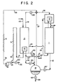
- Figures 1 and 2 illustrate the embodiment wherein the product ultra high purity oxygen is recovered as liquid stream 111.
- Product ultra high purity oxygen of this invention may be recovered as gas prior to condensation in condenser 13 or, as illustrated in Figures 1 and 2, it may be recovered as liquid after the condensation in condenser 13. In addition, the product ultra high purity oxygen may be recovered as both gas and liquid from both locations. Typically the product ultra high purity oxygen of this invention will have an oxygen purity of at least 99.999 percent and may have a purity of up to 99.99999 percent.
- Condenser 13 is driven by any suitable means.
- condenser 13 is driven by passing at least some of the condensed fluid from the condensing side of reboiler 12 by conduit means to the vaporizing side of condenser 13 wherein the fluid vaporizes to effect the aforesaid condensation of the ultra high purity oxygen.
- a portion 122 of the condensed fluid from reboiler 12 is passed through valve 123 and into the vaporizing side of condenser 13, while the remainder 124 is passed out of the process.
- the resulting vaporized fluid is passed from the vaporizing side of condenser 13 as stream 125 and into the cryogenic air separation plant.
- stream 125 is preferably passed into the upper column.
- a portion 32 of the condensed fluid from reboiler 12 is pumped by pump 17 and passed as stream 34 into the vaporizing side of condenser 13, while the remainder is passed out as stream 33.
- the resulting vaporized fluid is passed out of the vaporizing side of condenser 13 as stream 35.
- Descending liquid within the absorbing column containing absorbed heavy impurities is removed from the absorbing column as stream 112.
- stream 112 is passed into the cryogenic air separation plant; in the preferred double column case, stream 112 is passed into the plant at the main condenser.
- stream 112 preferably forms recycle fluid.
- Absorbing column 11 is operated such that methane absorbing factor A preferably exceeds 1.0 and most preferably exceeds 1.1.
- Methane absorbing factor A 1/kv where 1 is the liquid molar flow in the absorbing column, v is the vapor molar flow in the absorbing column, and k is the ratio of the mole fraction of methane impurity in the gas phase and the mole fraction of methane impurity in the liquid phase at thermodynamic equilibrium.
- absorbing column 11 serves to reduce the concentration of methane from stream, 110 to the product ultra high purity oxygen, such as might be recovered in stream 111, by about three orders of magnitude. Since methane is the most volatile of the heavy impurities, all other heavy impurities will be reduced in concentration by operation of the absorbing column by an even greater factor.
- Either of stripping column 10 or absorbing column 11, or both may be comprised of a series of vertically spaced trays or of column packing. Those skilled in the mass transfer art are familiar with the many types of trays and column packing available and no further detailed discussion is necessary here.
- liquid reservoir or tank 14 is fed by at least one, and preferably three, internal streams by conduit means.
- One reservoir feed stream is condensed fluid 33 from the condensing side of reboiler 12 which passes through valve 126 and into reservoir 14.
- Another reservoir feed stream is drain 102 from the lower portion, preferably the bottom, of stripping column 10.
- a third reservoir feed stream is stream 112 from the lower portion, preferably the bottom, of absorbing column 11 which is passed through valve 127 and into reservoir 14.
- vapor is flashed off the liquid and is passed out of the reservoir as stream 37. Flash vapor is produced due to throttling of saturated liquid across valves 120, 126 and 127.
- the flashed vapor is then passed, such by conduit means, to the condensing side of reboiler 12 to drive reboiler 12.
- stream 35 and 101 are combined with flashed vapor 37 to form stream 38 which is recycled to the condensing side of reboiler 12.
- Liquid stream 128 is passed out of reservoir 14 through valve 129.
- This stream would generally have an oxygen concentration of at least 99.5 percent and is recovered as commercial high purity oxygen. This stream is not recycled in order to prevent excess heavy impurity buildup.
- stream 37 In addition to stream 37, either one or both of two other streams could be passed, such as by conduit means, to the vaporizing side of reboiler 12.
- One such stream is stream 101 taken from the upper portion, preferably the top, of stripping column 10.
- the other stream is stream 35 which is vaporized fluid from the vaporizing side of condenser 13.
- Preferably all three of streams 37, 35 and 101 are passed to the condensing side of reboiler 12 to drive reboiler 12.
- Figure 2 illustrates a preferred embodiment wherein these three stream are combined, after stream 101 passes through valve 130, to form stream 38.
- Stream 38 is warmed by indirect heat exchange by passage through heat exchanger 15. Warmed stream 39 is compressed by compressor 16 and aftercooled by cooler 131. Stream 39 is then passed as reliquefaction feed stream 30 through heat exchanger 15 wherein it is cooled by indirect heat exchange against warming stream 38. The cooled reliquefaction stream emerges from heat exchanger 15 and is passed as stream 31 to the condensing side of reboiler 12 to drive reboiler 12. A portion 132 may be passed out of stream 39 through valve 133 prior to its becoming reliquefaction stream 30. The flowrate of stream 132 depends upon heat leakage into the process and could be nearly zero if a significant amount of the product ultra high purity oxygen is recovered in gaseous form.
- Table 1 The results of a computer simulation of the invention carried out with the embodiment illustrated in Figure 1 are presented in Table 1.
- the stream numbers in Table 1 correspond to those of Figure 1.
- the abreviation CFH stands for cubic foot per hour, at standard conditions of 1 atmosphere and 70 degrees Farenheit, °K stands for degrees Kelvin, and PPm stands for parts per million.
- the stripping column operated at an argon stripping factor of 1.2 and had 33 equilibrium stages or theoretical trays and the absorbing column operated at a methane absorbing factor of 1.2 and had 31 equilibrium stages or theoretical trays.
- the invention was operated as an addition to a double column air separation plant.
- the argon impurity is reduced from 4000 to 5 ppm and the methane impurity is reduced from 8.1 to 0.03 ppm.
- TABLE 1 Stream No. Flow, CFH Pressure, PSIA Temperature °K Impurity, PPM Argon Methane 100-liquid 8250 25.4 95.8 4000 8.1 101-gas 6620 25.4 95.8 4986 2.5 102-liquid 30 28.0 96.9 4 94.5 110-gas 1600 28.0 96.9 4 29.5 111-liquid 1000 25.4 95.8 5 0.03 112-liquid 600 28.0 96.5 2.5 78.6
- a major advantage of the embodiment of the invention such as is illustrated in Figure 1 is that there is no need for additional oxygen compression or additional heat pump compression.
- a major advantage of the standalone embodiment of the invention such as is illustrated in Figure 2 is that the state of oxygen is largely preserved, i.e. nearly all of the oxygen can be removed from the process in liquid form. This advantage is demonstrated by the data presented in Table 2 which is a computer simulation of the invention of the embodiment illustrated in Figure 2. The stream numbers in Table 2 correspond to those of Figure 2. TABLE 2 Stream No.
- stripping and absorbing columns were the same as, and were operated in manners similar to those, described with the embodiment illustrated in Figure 1, and values for stream numbers 100, 101, 102, 110, 111 and 112 were the same as those given in Table 1.
- oxygen effluent streams 111 and 128 equal 8160 CFH while feed stream 100 equals 8250 CFH resulting in liquid state conservation of about 99 percent.
Landscapes
- Engineering & Computer Science (AREA)
- Chemical & Material Sciences (AREA)
- Analytical Chemistry (AREA)
- Thermal Sciences (AREA)
- General Engineering & Computer Science (AREA)
- Mechanical Engineering (AREA)
- Physics & Mathematics (AREA)
- General Chemical & Material Sciences (AREA)
- Oil, Petroleum & Natural Gas (AREA)
- Chemical Kinetics & Catalysis (AREA)
- Health & Medical Sciences (AREA)
- Biomedical Technology (AREA)
- Environmental & Geological Engineering (AREA)
- Separation By Low-Temperature Treatments (AREA)
Applications Claiming Priority (2)
| Application Number | Priority Date | Filing Date | Title |
|---|---|---|---|
| US07/078,852 US4780118A (en) | 1987-07-28 | 1987-07-28 | Process and apparatus to produce ultra high purity oxygen from a liquid feed |
| US78852 | 1987-07-28 |
Publications (3)
| Publication Number | Publication Date |
|---|---|
| EP0301514A2 true EP0301514A2 (de) | 1989-02-01 |
| EP0301514A3 EP0301514A3 (en) | 1989-08-09 |
| EP0301514B1 EP0301514B1 (de) | 1992-01-02 |
Family
ID=22146593
Family Applications (1)
| Application Number | Title | Priority Date | Filing Date |
|---|---|---|---|
| EP88112153A Expired - Lifetime EP0301514B1 (de) | 1987-07-28 | 1988-07-27 | Verfahren und Apparat zur Erzeugung von ultrareinem Sauerstoff bei Flüssigbeschickung |
Country Status (7)
| Country | Link |
|---|---|
| US (1) | US4780118A (de) |
| EP (1) | EP0301514B1 (de) |
| JP (1) | JPS6446563A (de) |
| KR (1) | KR930000281B1 (de) |
| BR (1) | BR8803729A (de) |
| CA (1) | CA1285212C (de) |
| DE (1) | DE3867357D1 (de) |
Cited By (1)
| Publication number | Priority date | Publication date | Assignee | Title |
|---|---|---|---|---|
| EP1308681A1 (de) * | 2001-11-02 | 2003-05-07 | Linde Aktiengesellschaft | Verfahren und Vorrichtung zur Erzeugung einer hoch reinen Luftkomponente |
Families Citing this family (9)
| Publication number | Priority date | Publication date | Assignee | Title |
|---|---|---|---|---|
| DE3913880A1 (de) * | 1989-04-27 | 1990-10-31 | Linde Ag | Verfahren und vorrichtung zur tieftemperaturzerlegung von luft |
| US5058387A (en) * | 1989-07-05 | 1991-10-22 | The Boc Group, Inc. | Process to ultrapurify liquid nitrogen imported as back-up for nitrogen generating plants |
| US5195324A (en) * | 1992-03-19 | 1993-03-23 | Prazair Technology, Inc. | Cryogenic rectification system for producing nitrogen and ultra high purity oxygen |
| US5682763A (en) * | 1996-10-25 | 1997-11-04 | Air Products And Chemicals, Inc. | Ultra high purity oxygen distillation unit integrated with ultra high purity nitrogen purifier |
| US5918482A (en) * | 1998-02-17 | 1999-07-06 | Praxair Technology, Inc. | Cryogenic rectification system for producing ultra-high purity nitrogen and ultra-high purity oxygen |
| JP4467190B2 (ja) | 1998-11-09 | 2010-05-26 | 大陽日酸株式会社 | 酸素同位体重成分の濃縮方法および装置 |
| US6263701B1 (en) | 1999-09-03 | 2001-07-24 | Air Products And Chemicals, Inc. | Process for the purification of a major component containing light and heavy impurities |
| US6327873B1 (en) | 2000-06-14 | 2001-12-11 | Praxair Technology Inc. | Cryogenic rectification system for producing ultra high purity oxygen |
| KR100793107B1 (ko) * | 2007-10-15 | 2008-01-10 | (주)이에스 | 메탄가스정화시스템이 구비된 고효율 열병합 발전 시스템 |
Citations (2)
| Publication number | Priority date | Publication date | Assignee | Title |
|---|---|---|---|---|
| DE921809C (de) * | 1952-07-04 | 1954-12-30 | Adolf Messer G M B H | Verfahren zur Erzeugung von reinem Sauerstoff neben der Gewinnung von Sauerstoff geringerer Reinheit |
| FR1436385A (fr) * | 1964-06-02 | 1966-04-22 | Air Reduction | Perfectionnement à la production d'oxygène ultra-pur |
Family Cites Families (13)
| Publication number | Priority date | Publication date | Assignee | Title |
|---|---|---|---|---|
| US2519892A (en) * | 1945-01-16 | 1950-08-22 | Air Reduction | Method of producing liquid oxygen |
| US2815650A (en) * | 1955-07-01 | 1957-12-10 | Phillips Petroleum Co | Reboiled absorber operation |
| US3620032A (en) * | 1968-05-16 | 1971-11-16 | Air Liquide | Method for producing high-purity oxygen from commercially pure oxygen feed-stream |
| US3718006A (en) * | 1968-12-11 | 1973-02-27 | Linde Ag | Process for selective absorption |
| US4433990A (en) * | 1981-12-08 | 1984-02-28 | Union Carbide Corporation | Process to recover argon from oxygen-only air separation plant |
| US4410343A (en) * | 1981-12-24 | 1983-10-18 | Union Carbide Corporation | Air boiling process to produce low purity oxygen |
| GB2129115B (en) * | 1982-10-27 | 1986-03-12 | Air Prod & Chem | Producing gaseous nitrogen |
| US4448595A (en) * | 1982-12-02 | 1984-05-15 | Union Carbide Corporation | Split column multiple condenser-reboiler air separation process |
| US4543115A (en) * | 1984-02-21 | 1985-09-24 | Air Products And Chemicals, Inc. | Dual feed air pressure nitrogen generator cycle |
| US4560397A (en) * | 1984-08-16 | 1985-12-24 | Union Carbide Corporation | Process to produce ultrahigh purity oxygen |
| JPS61190277A (ja) * | 1985-02-16 | 1986-08-23 | 大同酸素株式会社 | 高純度窒素および酸素ガス製造装置 |
| JPS61262584A (ja) * | 1985-05-17 | 1986-11-20 | 株式会社日立製作所 | 空気分離方法及び装置 |
| US4615716A (en) * | 1985-08-27 | 1986-10-07 | Air Products And Chemicals, Inc. | Process for producing ultra high purity oxygen |
-
1987
- 1987-07-28 US US07/078,852 patent/US4780118A/en not_active Expired - Fee Related
-
1988
- 1988-07-27 EP EP88112153A patent/EP0301514B1/de not_active Expired - Lifetime
- 1988-07-27 JP JP63185701A patent/JPS6446563A/ja active Pending
- 1988-07-27 BR BR8803729A patent/BR8803729A/pt unknown
- 1988-07-27 KR KR1019880009453A patent/KR930000281B1/ko active IP Right Grant
- 1988-07-27 DE DE8888112153T patent/DE3867357D1/de not_active Expired - Lifetime
- 1988-07-27 CA CA000573176A patent/CA1285212C/en not_active Expired - Lifetime
Patent Citations (2)
| Publication number | Priority date | Publication date | Assignee | Title |
|---|---|---|---|---|
| DE921809C (de) * | 1952-07-04 | 1954-12-30 | Adolf Messer G M B H | Verfahren zur Erzeugung von reinem Sauerstoff neben der Gewinnung von Sauerstoff geringerer Reinheit |
| FR1436385A (fr) * | 1964-06-02 | 1966-04-22 | Air Reduction | Perfectionnement à la production d'oxygène ultra-pur |
Cited By (1)
| Publication number | Priority date | Publication date | Assignee | Title |
|---|---|---|---|---|
| EP1308681A1 (de) * | 2001-11-02 | 2003-05-07 | Linde Aktiengesellschaft | Verfahren und Vorrichtung zur Erzeugung einer hoch reinen Luftkomponente |
Also Published As
| Publication number | Publication date |
|---|---|
| JPS6446563A (en) | 1989-02-21 |
| KR890001623A (ko) | 1989-03-28 |
| BR8803729A (pt) | 1989-02-14 |
| EP0301514B1 (de) | 1992-01-02 |
| DE3867357D1 (de) | 1992-02-13 |
| US4780118A (en) | 1988-10-25 |
| CA1285212C (en) | 1991-06-25 |
| EP0301514A3 (en) | 1989-08-09 |
| KR930000281B1 (ko) | 1993-01-15 |
Similar Documents
| Publication | Publication Date | Title |
|---|---|---|
| US4560397A (en) | Process to produce ultrahigh purity oxygen | |
| US5402647A (en) | Cryogenic rectification system for producing elevated pressure nitrogen | |
| US4871382A (en) | Air separation process using packed columns for oxygen and argon recovery | |
| US4594085A (en) | Hybrid nitrogen generator with auxiliary reboiler drive | |
| US5098456A (en) | Cryogenic air separation system with dual feed air side condensers | |
| US6023945A (en) | Annular column for cryogenic rectification | |
| US5233838A (en) | Auxiliary column cryogenic rectification system | |
| US4568528A (en) | Process to produce a krypton-xenon concentrate and a gaseous oxygen product | |
| EP0301514A2 (de) | Verfahren und Apparat zur Erzeugung von ultrareinem Sauerstoff bei Flüssigbeschickung | |
| KR910002050B1 (ko) | 가압산소를 제조하기 위한 공기분리공정 | |
| US4902321A (en) | Cryogenic rectification process for producing ultra high purity nitrogen | |
| US4574006A (en) | Process to produce a krypton-xenon concentrate from a liquid feed | |
| US4755202A (en) | Process and apparatus to produce ultra high purity oxygen from a gaseous feed | |
| US5074898A (en) | Cryogenic air separation method for the production of oxygen and medium pressure nitrogen | |
| US4647299A (en) | Process to produce an oxygen-free krypton-xenon concentrate | |
| US5263327A (en) | High recovery cryogenic rectification system | |
| US4604117A (en) | Hybrid nitrogen generator with auxiliary column drive | |
| US5918482A (en) | Cryogenic rectification system for producing ultra-high purity nitrogen and ultra-high purity oxygen | |
| US5386691A (en) | Cryogenic air separation system with kettle vapor bypass | |
| EP0218741A1 (de) | Verfahren zur Gewinnung eines Krypton-Xenonkonzentrats und ein gasförmiges Sauerstoffprodukt | |
| US6276172B1 (en) | Process for producing ultrapure nitrogen | |
| EP0218740B1 (de) | Verfahren zum Gewinnen eines Krypton-Xenonkonzentrats aus einer flüssigen Mischung | |
| US5666828A (en) | Cryogenic hybrid system for producing low purity oxygen and high purity oxygen | |
| KR960003274B1 (ko) | 혼성아르곤컬럼을 갖는 저온공기분리시스템 |
Legal Events
| Date | Code | Title | Description |
|---|---|---|---|
| PUAI | Public reference made under article 153(3) epc to a published international application that has entered the european phase |
Free format text: ORIGINAL CODE: 0009012 |
|
| AK | Designated contracting states |
Kind code of ref document: A2 Designated state(s): BE DE ES FR IT |
|
| PUAL | Search report despatched |
Free format text: ORIGINAL CODE: 0009013 |
|
| AK | Designated contracting states |
Kind code of ref document: A3 Designated state(s): BE DE ES FR IT |
|
| 17P | Request for examination filed |
Effective date: 19890825 |
|
| 17Q | First examination report despatched |
Effective date: 19900419 |
|
| ITF | It: translation for a ep patent filed | ||
| GRAA | (expected) grant |
Free format text: ORIGINAL CODE: 0009210 |
|
| AK | Designated contracting states |
Kind code of ref document: B1 Designated state(s): BE DE ES FR IT |
|
| PG25 | Lapsed in a contracting state [announced via postgrant information from national office to epo] |
Ref country code: FR Effective date: 19920102 Ref country code: ES Free format text: THE PATENT HAS BEEN ANNULLED BY A DECISION OF A NATIONAL AUTHORITY Effective date: 19920102 Ref country code: BE Effective date: 19920102 |
|
| REF | Corresponds to: |
Ref document number: 3867357 Country of ref document: DE Date of ref document: 19920213 |
|
| EN | Fr: translation not filed | ||
| PLBE | No opposition filed within time limit |
Free format text: ORIGINAL CODE: 0009261 |
|
| STAA | Information on the status of an ep patent application or granted ep patent |
Free format text: STATUS: NO OPPOSITION FILED WITHIN TIME LIMIT |
|
| 26N | No opposition filed | ||
| PG25 | Lapsed in a contracting state [announced via postgrant information from national office to epo] |
Ref country code: DE Effective date: 19930401 |
|
| PG25 | Lapsed in a contracting state [announced via postgrant information from national office to epo] |
Ref country code: IT Free format text: LAPSE BECAUSE OF NON-PAYMENT OF DUE FEES;WARNING: LAPSES OF ITALIAN PATENTS WITH EFFECTIVE DATE BEFORE 2007 MAY HAVE OCCURRED AT ANY TIME BEFORE 2007. THE CORRECT EFFECTIVE DATE MAY BE DIFFERENT FROM THE ONE RECORDED. Effective date: 20050727 |