EP0300964A1 - Apparatus for mixing media capable of flowing - Google Patents
Apparatus for mixing media capable of flowing Download PDFInfo
- Publication number
- EP0300964A1 EP0300964A1 EP88810472A EP88810472A EP0300964A1 EP 0300964 A1 EP0300964 A1 EP 0300964A1 EP 88810472 A EP88810472 A EP 88810472A EP 88810472 A EP88810472 A EP 88810472A EP 0300964 A1 EP0300964 A1 EP 0300964A1
- Authority
- EP
- European Patent Office
- Prior art keywords
- hollow body
- bore
- wall
- flow
- annular gap
- Prior art date
- Legal status (The legal status is an assumption and is not a legal conclusion. Google has not performed a legal analysis and makes no representation as to the accuracy of the status listed.)
- Granted
Links
- 238000002347 injection Methods 0.000 claims abstract description 26
- 239000007924 injection Substances 0.000 claims abstract description 26
- 230000001804 emulsifying effect Effects 0.000 claims abstract description 19
- 239000000203 mixture Substances 0.000 claims abstract description 10
- 239000012530 fluid Substances 0.000 claims abstract description 8
- 239000007789 gas Substances 0.000 claims abstract description 4
- 230000002708 enhancing effect Effects 0.000 claims description 6
- 230000001965 increasing effect Effects 0.000 claims description 4
- 230000001154 acute effect Effects 0.000 claims description 2
- 229940090044 injection Drugs 0.000 description 20
- XLYOFNOQVPJJNP-UHFFFAOYSA-N water Substances O XLYOFNOQVPJJNP-UHFFFAOYSA-N 0.000 description 11
- 239000000839 emulsion Substances 0.000 description 9
- 239000012071 phase Substances 0.000 description 9
- 239000000126 substance Substances 0.000 description 5
- 238000003780 insertion Methods 0.000 description 4
- 230000037431 insertion Effects 0.000 description 4
- 238000004519 manufacturing process Methods 0.000 description 3
- 238000004945 emulsification Methods 0.000 description 2
- 230000004048 modification Effects 0.000 description 2
- 238000012986 modification Methods 0.000 description 2
- 239000007787 solid Substances 0.000 description 2
- 239000002253 acid Substances 0.000 description 1
- 150000007513 acids Chemical class 0.000 description 1
- 239000008346 aqueous phase Substances 0.000 description 1
- 239000003518 caustics Substances 0.000 description 1
- 238000010276 construction Methods 0.000 description 1
- 230000000694 effects Effects 0.000 description 1
- 239000003995 emulsifying agent Substances 0.000 description 1
- 238000005265 energy consumption Methods 0.000 description 1
- 230000002209 hydrophobic effect Effects 0.000 description 1
- 239000012535 impurity Substances 0.000 description 1
- 239000008384 inner phase Substances 0.000 description 1
- 238000000034 method Methods 0.000 description 1
- 239000002245 particle Substances 0.000 description 1
- 238000007789 sealing Methods 0.000 description 1
- 238000000926 separation method Methods 0.000 description 1
- 239000000243 solution Substances 0.000 description 1
- 230000003068 static effect Effects 0.000 description 1
Images


Classifications
-
- B—PERFORMING OPERATIONS; TRANSPORTING
- B01—PHYSICAL OR CHEMICAL PROCESSES OR APPARATUS IN GENERAL
- B01F—MIXING, e.g. DISSOLVING, EMULSIFYING OR DISPERSING
- B01F25/00—Flow mixers; Mixers for falling materials, e.g. solid particles
- B01F25/40—Static mixers
- B01F25/42—Static mixers in which the mixing is affected by moving the components jointly in changing directions, e.g. in tubes provided with baffles or obstructions
- B01F25/43—Mixing tubes, e.g. wherein the material is moved in a radial or partly reversed direction
- B01F25/433—Mixing tubes wherein the shape of the tube influences the mixing, e.g. mixing tubes with varying cross-section or provided with inwardly extending profiles
-
- B—PERFORMING OPERATIONS; TRANSPORTING
- B01—PHYSICAL OR CHEMICAL PROCESSES OR APPARATUS IN GENERAL
- B01F—MIXING, e.g. DISSOLVING, EMULSIFYING OR DISPERSING
- B01F25/00—Flow mixers; Mixers for falling materials, e.g. solid particles
- B01F25/30—Injector mixers
- B01F25/31—Injector mixers in conduits or tubes through which the main component flows
- B01F25/312—Injector mixers in conduits or tubes through which the main component flows with Venturi elements; Details thereof
- B01F25/3121—Injector mixers in conduits or tubes through which the main component flows with Venturi elements; Details thereof with additional mixing means other than injector mixers, e.g. screens, baffles or rotating elements
Definitions
- an apparatus of the invention comprises an injection nozzle for injecting pre-mixed media and a hollow body with a bore, disposed mirror-inverted and at a small distance thereto, the outlet end of said nozzle and inlet end of said hollow body, seen in the direction of flow, being a part of an annular gap working as pre-emulsifying chamber, said inlet end of the hollow body with the bore being sharp-edged, and further comprising a following homogenizing chamber having at its internal walls means for enhancing the turbulence of the mixture.
- the apparatus of a second embodiment comprises further at least one injection channel disposed perpendicularly to the injection nozzle for the continuous phase, said injection channel reaching into the annular gap for injecting the discontinuous phase.
- the apparatus of a first preferred embodiment of the invention for emulsifying pre-mixed media are best shown in the figures 4 and 6, disregarding the injection channel 3.
- the apparatus comprises an injection nozzle1, opposite and in a small distance to it, a hollow body in the form of a truncated cone 7, disposed in a mirror-inverted manner, and a homogenizing chamber 5, having at its internal surface 12 swirling means 13 (Fig. 1).
- the said sharp-edged front part 8 is the inlet front end of the inner wall, formed around the bore 28.
Landscapes
- Chemical & Material Sciences (AREA)
- Chemical Kinetics & Catalysis (AREA)
- Dispersion Chemistry (AREA)
- Coating Apparatus (AREA)
Abstract
Description
- The present invention relates to an apparatus for mixing, dispersing, and emulsifying media capable to flow, for example gases or fluids, in particular for the production of emulsions. Different methods and apparatus are known for dispersing and emulsifying media capable to flow, such as rotating systems with a rotor and a stator with teeth, whereby the media are sheared and dispersed or emulsified. Another group comprises high pressure systems, up to a pressure of 5x10⁷Pa, where the fluids are ejected at high pressure and therefore high velocity from a nozzle. A third, low pressure - up to 2x10⁶Pa - system is known for example from the Austrian Patent No. 329,012, comprising a mixing chamber with a torus arranged around the inlet nozzle, said torus being conical on the inlet side, and further comprising at the opposite mixing chamber wall a corresponding, parallely arranged conical surface for building an annular gap for obtaining a cavitation of the medium to be mixed. The inlet pipe and the mixing chamber walls comprise twist generating elements.
- However, it appeared that this apparatus, althought an improvement over the prior art existing at that time could not treat all media in a satifactorily manner.
- It is therefore an object of the present invention to provide an apparatus for treating media capable to flow with an improved mixing ability and increased stability, in particular for difficult to emulgate media, such as for example few water in much oil. To solve this problem a first embodiment of an apparatus of the invention comprises an injection nozzle for injecting pre-mixed media and a hollow body with a bore, disposed mirror-inverted and at a small distance thereto, the outlet end of said nozzle and inlet end of said hollow body, seen in the direction of flow, being a part of an annular gap working as pre-emulsifying chamber, said inlet end of the hollow body with the bore being sharp-edged, and further comprising a following homogenizing chamber having at its internal walls means for enhancing the turbulence of the mixture.
- The apparatus of a second embodiment comprises further at least one injection channel disposed perpendicularly to the injection nozzle for the continuous phase, said injection channel reaching into the annular gap for injecting the discontinuous phase.
- The invention will be described further by way of examples with reference to the accompanying drawings, in which:
- Figure 1 shows in a partial longitudinal section the main parts of the apparatus according to the invention,
- Figures 2 and 3 show each a modification of the embodiment of Figure 1,
- Figure 4 shows in an enlarged scale the slightly modified apparatus of Figure 1,
- Figure 5 shows a modification of Figure 4,
- Figure 6 shows in an exploded view parts of the apparatus according to Figure 1,
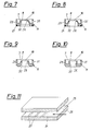
- Figures 7-10 show several embodiments of the pre-emulsifying chamber, and
- Figure 11 shows schematically a parallelepipedic homogenizing chamber.
- The main parts of the apparatus of a first preferred embodiment of the invention for emulsifying pre-mixed media are best shown in the figures 4 and 6, disregarding the
injection channel 3. According to it the apparatus comprises an injection nozzle1, opposite and in a small distance to it, a hollow body in the form of a truncatedcone 7, disposed in a mirror-inverted manner, and ahomogenizing chamber 5, having at itsinternal surface 12 swirling means 13 (Fig. 1). - Between the
end 9 of the conicallyshaped injection nozzle 1 and the front of the hollow truncated cone 7 apre-emulsifying chamber 2 is build, in the form of a smallannular gap 10. The front of the hollowtruncated cone 7, looking toward the injection nozzle, is formed assharp edge 8. The hollow part 4 of thebody 7, thechamber 5, and thepiece 6 form the homogenizer; part 4 in thehollow body 7 being the inlet, and piece 6 (Fig. 4) the outlet of it. - The figures 1-10 show different variations of the
hollow body 7. The figures 1-6, and 7 show a truncated cone as hollow body, figures 8 and 9 with concave, resp. convex sides. Figure 10 shows a cylindrical hollow body. It follows in particular from the figures 7-10 that thehollow body 7 is contained in aninsertion piece 11 and that theannular gap 10 is formed around thebore 28 ofbody 7 thus as to obtain anouter wall 29 and aninner wall 30, wherein theouter wall 30 is higher thaninner wall 29. The function ofaperture 31, also shown in those figures, will be explained later on. At its outlet side theinsertion piece 11 contains a recess for receiving a O-ring 21. - It follows also that the said sharp-edged
front part 8 is the inlet front end of the inner wall, formed around thebore 28. - The aim of each mixing, emulsifying or dispersing apparatus is to achieve a fine and homogen mixture of the components. In the case of media capable to flow, like fluids, it is important to disrupt any film formed by the media, for instance by water and oil respectively. The sharp-edged front of the hollow body, the annular gap between said body and the injection nozzle are some of the very effective means to disrupt any film and to achieve pre-emulsification of injected pre-mixed media.
- Emulsions are systems with at least two phases, which are not or only to a small extent soluble one in another. It is distinguished between a continuous phase, in which the other, the discontinuous one is distributed in the form of small droplets, forming two groups. There are the oil-in-water and the water-in-oil emulsions. Every high polar, hydrophile fluid fells into the category water, whereas the hydrophobic, non-polar fluids are looked at as oil. If oil and water are brought together and treated very strongly mechanically, one is dispersed into the other and a multitude of droplets are formed. If the system stays at rest, differences in the density leads to the separation of the phases. By admixing substances for lowering the surface tension, the coalescense is stopped. The invention allows a substantial improvement of the problem of manufacturing stable mixtures, in particular emulsions.
- A further important item of the invention is the
homogenizing chamber 5, to which the mixture arrives through the short inlet piece 4, the cavity of thehollow body 7. Theinternal surface 12 ofchamber 5 is rough, for enhancing and maintaining the swirling effect of theannular gap 10 andsharp edge 8, hindering a film to form. Thehomogenizing chamber 5 can have any shape, a cylindrical, elliptical, conical or rectangular section. According to a first embodiment, the roughness of theinternal surface 12 can be effectuated by insertedsmall plates 13, with one orseveral bores 14 each, said bores having different edges, sharp or not, or being in the form of a sharp-edged thread 15 (Fig. 6), or the like other edged or rough means. Figure 6 shows from the left to the right thehollow body 7 with thesharp edge 8 at the bore, contained in theinsertion piece 11, afirst plate 13 with abore 14 having aninternal edge 16, asecond plate 13 withbore 14 having anotherinternal edge 17, a third and afourth plate 13 with abore 14 havingdifferent edges internal thread 15. - The
outlet piece 6 can have like the homogenizing chamber a cylindrical, elliptical, conical or rectangular section. The substantial parameters for the flow and the degree of quality of the emulsion are mainly the homogenizing pressure, the volume flow, the density of the media to be mixed as well as their viscosity and the geometries of the nozzle, of the pre-emulsifying chamber, of the homogenizing chamber, and of the outlet piece; and at least of the condition of flow. - Figure 11 shows a parallelepipedic
homogenizing chamber 24 with parallel to each other arrangedlateral walls ribs 27 instead of theplates 13, for enhancing the turbulence of the flow of the pre-emulsion. The ribs are disposed transversally to the direction of the flow, indicated by an arrow. - As mentioned before, the media to be mixed, homogenized, emulsified or dispersed can be pre-mixed and injected by the
injection nozzle 1, from where it impinges on thesharp edge 8 of the hollow body and into the small annular gap, resulting in a pre-emulsification which is completed in thehomogenizing chamber 5. - There exist media where pre-mixing is not desired or feasible. One of such system is a water-in-oil system where the water is injected separatedly. In the preferred second embodiment of the invention the supporting medium, for example oil, is injected by
injection nozzle 1. Thereby it is possible to use a not shown inlet pipe comprising twist generating means according to the Austrian Patent No. 329,012. The second medium, for example water, is injected by aninjection channel 3, as best shown in Fig. 4.Injection channel 3 is disposed perpendicularly toinjection nozzle 1 and reaches via aperture 31 (Figures 7-10) into theannular gap 10, where the water impinges on the swirled oil. In this case, the annular gap functions as pre-mixing and pre-emulsifying chamber. - The water can contain solid particles, and instead of water acids or caustic solutions can be treated.
- The
injection channel 3 is constructed asinsertion part 23, comprising a O-ring 22 for sealing it. In thepre-mixing chamber 10 the second medium, the discontinuous phase, water, is admixed perpendicularly to the main medium, the continuous phase, oil, ring-like around the thin-walledhollow body 7. Thesharp edge 8 is very important in this connection, with which the film building up at the innner wall of the hollow body is torn apart, causing a good pre-mixing and pre-emulsifying. - In particular, the dispersing or comminution of the medium, resp. media is achieved such, that one phase is injected under pressure by an injection nozzle into the
pre-emulsifying chamber 2 into which the further phase, according to the construction, is either sucked in by the injection action or pumped in. In thispre-emulsifying chamber 2, which is constructed asannular gap 10 with thesharp edge 8, the inner phase is pre-comminuted for the following homogenizing. The pre-emulsified mixture is subsequently treated as in the first example. - The apparatus according to the invention is particularly valuable for the production of stable emulsions. Instead of oil, any fat substance can be treated, and also aqueous phases. The media can contain pre-distributed solid substances, for example catalysators.
- It is also possible to provide the apparatus with more than one
injection channel 3, necessitating to provide for an aperture in the annular gap for each injection channel. - The apparatus according to the invention can be qualified as static low pressure homogenizator, that is, besides the pump(s) no moveable parts are required, and it is possible to work with relatively thin walls. Low pressure results also in low energy consumption. The medium injected through the
main injection nozzle 1 needs a pressure of about 1 to 20 x 10⁵Pa (1 to 20 Bar), preferably 10 x 10⁵Pa. - By maintaining determined values of the parameters it is possible to obtain very good and stable emulsions, resp. a very good thoroughly mixing by mechanical-physical treatment, so that the addition of chemical emulsifying agents can be substantially omitted. Thus, the emulsions can be preserved substantially in its chemical structure. It is further possible, by variating the geometries of the four main elements, namely injector nozzle, pre-emulsifying chamber (annular gap), homogenizing chamber and outlet piece, to exclude nearly totally cavitation and thus the addition of impurities.
Claims (10)
Applications Claiming Priority (2)
| Application Number | Priority Date | Filing Date | Title |
|---|---|---|---|
| AT1761/87 | 1987-07-13 | ||
| AT176187 | 1987-07-13 |
Publications (2)
| Publication Number | Publication Date |
|---|---|
| EP0300964A1 true EP0300964A1 (en) | 1989-01-25 |
| EP0300964B1 EP0300964B1 (en) | 1994-08-17 |
Family
ID=3520432
Family Applications (1)
| Application Number | Title | Priority Date | Filing Date |
|---|---|---|---|
| EP88810472A Expired - Lifetime EP0300964B1 (en) | 1987-07-13 | 1988-07-08 | Apparatus for mixing media capable of flowing |
Country Status (5)
| Country | Link |
|---|---|
| US (1) | US4989988A (en) |
| EP (1) | EP0300964B1 (en) |
| JP (1) | JPS6434426A (en) |
| AT (1) | ATE110002T1 (en) |
| DE (1) | DE3851106T2 (en) |
Cited By (8)
| Publication number | Priority date | Publication date | Assignee | Title |
|---|---|---|---|---|
| EP0350858A1 (en) * | 1988-07-11 | 1990-01-17 | M&T CHEMICALS GMBH Galvanotechnik Spezialchemikalien | Process for separating nickel from diluted aqueous solutions containing nickel ions |
| LT3894B (en) | 1989-05-05 | 1996-04-25 | Framo Dev Ltd | Multiphase process mixing and measuring system |
| WO2000067892A1 (en) * | 1999-05-07 | 2000-11-16 | Astrazeneca Ab | Method and device for forming particles |
| WO2006038810A1 (en) * | 2004-10-01 | 2006-04-13 | Propure As | Multi fluid injection mixer |
| CN100540128C (en) * | 2004-10-01 | 2009-09-16 | 普罗普里公司 | Multi-Fluid Injection Mixer |
| RU179469U1 (en) * | 2017-12-25 | 2018-05-15 | Акционерное общество "ГМС Нефтемаш" | Device for increasing flow uniformity |
| US11673104B2 (en) | 2018-12-07 | 2023-06-13 | Produced Water Absorbents Inc. | Multi-fluid injection mixer and related methods |
| US11833481B2 (en) | 2018-10-05 | 2023-12-05 | Produced Water Absorbents Inc. | Multi-channel, variable-flow mixers and related methods |
Families Citing this family (17)
| Publication number | Priority date | Publication date | Assignee | Title |
|---|---|---|---|---|
| DE3916465A1 (en) * | 1989-05-20 | 1990-11-22 | Bayer Ag | PRODUCTION OF SPHERICAL DISPERSIONS BY CRYSTALLIZATION OF EMULSIONS |
| CN1066916A (en) * | 1991-05-20 | 1992-12-09 | 谢志强 | The technology for mixing water in heavy oil of emulsifier free and emulsifier unit |
| JP2683168B2 (en) * | 1991-05-30 | 1997-11-26 | シャープ株式会社 | Contact charging device |
| US5624186A (en) * | 1996-02-06 | 1997-04-29 | Chem Financial, Inc. | Multi-chamber high pressure dispersion apparatus |
| AU1807997A (en) * | 1996-02-06 | 1997-08-28 | Chem Financial, Inc. | Multi-chamber high pressure dispersion apparatus |
| US6443610B1 (en) | 1998-12-23 | 2002-09-03 | B.E.E. International | Processing product components |
| DE102004041770A1 (en) * | 2004-08-28 | 2006-03-02 | Tetra Laval Holdings & Finance S.A. | Device and method for microparticulation of filtration retentates |
| NO343579B1 (en) * | 2004-10-01 | 2019-04-08 | Propure As | injection Mixer |
| US20080061008A1 (en) * | 2006-09-12 | 2008-03-13 | Kelsey Robert L | Systems and methods for treating metalworking fluids |
| CA2678227A1 (en) * | 2007-02-13 | 2008-08-21 | Vrtx Technologies, Llc | Systems and methods for treatment of wastewater |
| US7651621B2 (en) * | 2007-04-18 | 2010-01-26 | Vrtx Technologies, Llc | Methods for degassing one or more fluids |
| US20080257411A1 (en) * | 2007-04-18 | 2008-10-23 | Kelsey Robert L | Systems and methods for preparation of emulsions |
| US20080257828A1 (en) * | 2007-04-18 | 2008-10-23 | Kelsey Robert L | Systems and methods for reduction of metal contaminants in fluids |
| US20090152212A1 (en) * | 2007-04-18 | 2009-06-18 | Kelsey Robert L | Systems and methods for treatment of groundwater |
| US7887862B2 (en) * | 2007-10-10 | 2011-02-15 | Industrias Centli S.A. De C.V. | Method and apparatus for separating, purifying, promoting interaction and improving combustion |
| BRPI0802233A2 (en) * | 2008-06-30 | 2010-03-02 | Inst Nac De Tecnologia | nanoparticle production process containing active substances and their pharmaceutical compositions |
| US9546351B2 (en) | 2010-04-12 | 2017-01-17 | Industrias Centli, S.A. De C.V. | Method and system for processing biomass |
Citations (4)
| Publication number | Priority date | Publication date | Assignee | Title |
|---|---|---|---|---|
| DE1557212A1 (en) * | 1967-05-26 | 1970-04-02 | Schoppe Fritz | Method for mixing a liquid with at least one second gaseous, liquid or powdery component and device for carrying out the method |
| AT329012B (en) * | 1972-03-13 | 1976-04-26 | Hutter Karl | DEVICE FOR MIXING ELECTRIC MEDIA |
| US4026817A (en) * | 1974-07-04 | 1977-05-31 | Snam Progetti S.P.A. | Method for the preparation in a continuous way of water/oil emulsions and apparatus suitable therefor |
| US4416610A (en) * | 1980-03-14 | 1983-11-22 | Hydroil, Inc. | Water-in-oil emulsifier and oil-burner boiler system incorporating such emulsifier |
Family Cites Families (8)
| Publication number | Priority date | Publication date | Assignee | Title |
|---|---|---|---|---|
| US1140548A (en) * | 1914-06-08 | 1915-05-25 | John B Vogelsang | Device for combining and emulsifying substances. |
| US2656648A (en) * | 1942-01-28 | 1953-10-27 | Friedmann Giovanni | Means for transporting and distributing fertilizers on fields |
| US3788557A (en) * | 1970-02-02 | 1974-01-29 | Spirolet Corp | Liquid injection adaptor |
| DE2310321B1 (en) * | 1973-03-01 | 1974-01-31 | Int Laboratoriums App Gmbh | EMULSIFYING AND DISPERSING DEVICE WITH ROTATING CONCENTRIC TOOL EDGE |
| US4127332A (en) * | 1976-11-19 | 1978-11-28 | Daedalean Associates, Inc. | Homogenizing method and apparatus |
| ZA841337B (en) * | 1983-03-02 | 1984-10-31 | Leschonski K | A method of and an apparatus for producing a gas-solid two phase flow jet having a constant mass or volume flow rate and predetermined velocity |
| SU1326326A1 (en) * | 1985-10-01 | 1987-07-30 | Ивано-Франковский Институт Нефти И Газа | Vortex mixer |
| US4811786A (en) * | 1985-10-31 | 1989-03-14 | Chevron Research Company | Downhole gaseous liquid flow agitator |
-
1988
- 1988-07-08 DE DE3851106T patent/DE3851106T2/en not_active Expired - Fee Related
- 1988-07-08 EP EP88810472A patent/EP0300964B1/en not_active Expired - Lifetime
- 1988-07-08 AT AT88810472T patent/ATE110002T1/en not_active IP Right Cessation
- 1988-07-12 JP JP63173635A patent/JPS6434426A/en active Pending
- 1988-07-13 US US07/218,306 patent/US4989988A/en not_active Expired - Fee Related
Patent Citations (4)
| Publication number | Priority date | Publication date | Assignee | Title |
|---|---|---|---|---|
| DE1557212A1 (en) * | 1967-05-26 | 1970-04-02 | Schoppe Fritz | Method for mixing a liquid with at least one second gaseous, liquid or powdery component and device for carrying out the method |
| AT329012B (en) * | 1972-03-13 | 1976-04-26 | Hutter Karl | DEVICE FOR MIXING ELECTRIC MEDIA |
| US4026817A (en) * | 1974-07-04 | 1977-05-31 | Snam Progetti S.P.A. | Method for the preparation in a continuous way of water/oil emulsions and apparatus suitable therefor |
| US4416610A (en) * | 1980-03-14 | 1983-11-22 | Hydroil, Inc. | Water-in-oil emulsifier and oil-burner boiler system incorporating such emulsifier |
Cited By (12)
| Publication number | Priority date | Publication date | Assignee | Title |
|---|---|---|---|---|
| EP0350858A1 (en) * | 1988-07-11 | 1990-01-17 | M&T CHEMICALS GMBH Galvanotechnik Spezialchemikalien | Process for separating nickel from diluted aqueous solutions containing nickel ions |
| LT3894B (en) | 1989-05-05 | 1996-04-25 | Framo Dev Ltd | Multiphase process mixing and measuring system |
| WO2000067892A1 (en) * | 1999-05-07 | 2000-11-16 | Astrazeneca Ab | Method and device for forming particles |
| US6551532B1 (en) | 1999-05-07 | 2003-04-22 | Astrazeneca Ab | Method and device for forming particles |
| AU759786B2 (en) * | 1999-05-07 | 2003-05-01 | Astrazeneca Ab | Method and device for forming particles |
| WO2006038810A1 (en) * | 2004-10-01 | 2006-04-13 | Propure As | Multi fluid injection mixer |
| EA012104B1 (en) * | 2004-10-01 | 2009-08-28 | Пропуре Ас | Multi fluid injection mixer |
| CN100540128C (en) * | 2004-10-01 | 2009-09-16 | 普罗普里公司 | Multi-Fluid Injection Mixer |
| US10710033B2 (en) | 2004-10-01 | 2020-07-14 | Produced Water Absorbents, Inc. | Multi fluid injection mixer |
| RU179469U1 (en) * | 2017-12-25 | 2018-05-15 | Акционерное общество "ГМС Нефтемаш" | Device for increasing flow uniformity |
| US11833481B2 (en) | 2018-10-05 | 2023-12-05 | Produced Water Absorbents Inc. | Multi-channel, variable-flow mixers and related methods |
| US11673104B2 (en) | 2018-12-07 | 2023-06-13 | Produced Water Absorbents Inc. | Multi-fluid injection mixer and related methods |
Also Published As
| Publication number | Publication date |
|---|---|
| ATE110002T1 (en) | 1994-09-15 |
| EP0300964B1 (en) | 1994-08-17 |
| DE3851106D1 (en) | 1994-09-22 |
| US4989988A (en) | 1991-02-05 |
| JPS6434426A (en) | 1989-02-03 |
| DE3851106T2 (en) | 1994-12-01 |
Similar Documents
| Publication | Publication Date | Title |
|---|---|---|
| EP0300964A1 (en) | Apparatus for mixing media capable of flowing | |
| US4441823A (en) | Static line mixer | |
| EP1280598B1 (en) | Cavitation mixer | |
| US4674888A (en) | Gaseous injector for mixing apparatus | |
| DE4433744C2 (en) | Device for mixing media to produce liquid systems | |
| US4908154A (en) | Method of forming a microemulsion | |
| RU2239492C2 (en) | Method of homogenization of a pressured thin emulsion | |
| US4533254A (en) | Apparatus for forming emulsions | |
| RU2553861C1 (en) | Hydrodynamic mixer | |
| EP4323094B1 (en) | Device and method for dispersing gases into liquids | |
| JP5143942B2 (en) | Refinement mixing equipment | |
| JP2015027675A (en) | Method and apparatus for phase inversion by using stationary type mixer and coagulator | |
| US20080257411A1 (en) | Systems and methods for preparation of emulsions | |
| RU2223815C1 (en) | Method of preparation of emulsion and system and device for realization of this method | |
| WO2014134115A1 (en) | Variable velocity apparatus and method for blending and emulsifying | |
| JP4879232B2 (en) | Refinement mixing equipment | |
| RU2021005C1 (en) | Hydrodynamic homogenizer-mixer | |
| RU2075619C1 (en) | Device for processing liquid fuel by cavitation | |
| DE2242348C3 (en) | Device for generating vibrations in liquids | |
| JP5285231B2 (en) | Mixing equipment | |
| RU2619783C1 (en) | Acoustic mixer | |
| SU1502064A1 (en) | Method and apparatus for atomizing liquids in flow | |
| KR880003102Y1 (en) | Sludge Grinding Emulsifier | |
| RU64938U1 (en) | GAS-LIQUID DISPERSANT | |
| RU2167704C2 (en) | Emulsifier |
Legal Events
| Date | Code | Title | Description |
|---|---|---|---|
| PUAI | Public reference made under article 153(3) epc to a published international application that has entered the european phase |
Free format text: ORIGINAL CODE: 0009012 |
|
| AK | Designated contracting states |
Kind code of ref document: A1 Designated state(s): AT BE CH DE ES FR GB IT LI LU NL SE |
|
| 17P | Request for examination filed |
Effective date: 19890722 |
|
| 17Q | First examination report despatched |
Effective date: 19910517 |
|
| GRAA | (expected) grant |
Free format text: ORIGINAL CODE: 0009210 |
|
| AK | Designated contracting states |
Kind code of ref document: B1 Designated state(s): AT BE CH DE ES FR GB IT LI LU NL SE |
|
| PG25 | Lapsed in a contracting state [announced via postgrant information from national office to epo] |
Ref country code: IT Free format text: LAPSE BECAUSE OF FAILURE TO SUBMIT A TRANSLATION OF THE DESCRIPTION OR TO PAY THE FEE WITHIN THE PRE;WARNING: LAPSES OF ITALIAN PATENTS WITH EFFECTIVE DATE BEFORE 2007 MAY HAVE OCCURRED AT ANY TIME BEFORE 2007. THE CORRECT EFFECTIVE DATE MAY BE DIFFERENT FROM THE ONE RECORDED.SCRIBED TIME-LIMIT Effective date: 19940817 Ref country code: NL Effective date: 19940817 Ref country code: ES Free format text: THE PATENT HAS BEEN ANNULLED BY A DECISION OF A NATIONAL AUTHORITY Effective date: 19940817 Ref country code: BE Effective date: 19940817 |
|
| REF | Corresponds to: |
Ref document number: 110002 Country of ref document: AT Date of ref document: 19940915 Kind code of ref document: T |
|
| REF | Corresponds to: |
Ref document number: 3851106 Country of ref document: DE Date of ref document: 19940922 |
|
| PG25 | Lapsed in a contracting state [announced via postgrant information from national office to epo] |
Ref country code: SE Effective date: 19941117 |
|
| ET | Fr: translation filed | ||
| NLV1 | Nl: lapsed or annulled due to failure to fulfill the requirements of art. 29p and 29m of the patents act | ||
| PLBE | No opposition filed within time limit |
Free format text: ORIGINAL CODE: 0009261 |
|
| STAA | Information on the status of an ep patent application or granted ep patent |
Free format text: STATUS: NO OPPOSITION FILED WITHIN TIME LIMIT |
|
| PGFP | Annual fee paid to national office [announced via postgrant information from national office to epo] |
Ref country code: GB Payment date: 19950620 Year of fee payment: 8 |
|
| PGFP | Annual fee paid to national office [announced via postgrant information from national office to epo] |
Ref country code: FR Payment date: 19950710 Year of fee payment: 8 |
|
| PG25 | Lapsed in a contracting state [announced via postgrant information from national office to epo] |
Ref country code: LU Free format text: LAPSE BECAUSE OF NON-PAYMENT OF DUE FEES Effective date: 19950731 |
|
| 26N | No opposition filed | ||
| PG25 | Lapsed in a contracting state [announced via postgrant information from national office to epo] |
Ref country code: GB Effective date: 19960708 |
|
| PGFP | Annual fee paid to national office [announced via postgrant information from national office to epo] |
Ref country code: AT Payment date: 19960731 Year of fee payment: 9 |
|
| GBPC | Gb: european patent ceased through non-payment of renewal fee |
Effective date: 19960708 |
|
| PG25 | Lapsed in a contracting state [announced via postgrant information from national office to epo] |
Ref country code: FR Effective date: 19970328 |
|
| REG | Reference to a national code |
Ref country code: FR Ref legal event code: ST |
|
| PG25 | Lapsed in a contracting state [announced via postgrant information from national office to epo] |
Ref country code: AT Free format text: LAPSE BECAUSE OF NON-PAYMENT OF DUE FEES Effective date: 19970708 |
|
| PGFP | Annual fee paid to national office [announced via postgrant information from national office to epo] |
Ref country code: DE Payment date: 20020731 Year of fee payment: 15 |
|
| PG25 | Lapsed in a contracting state [announced via postgrant information from national office to epo] |
Ref country code: DE Free format text: LAPSE BECAUSE OF NON-PAYMENT OF DUE FEES Effective date: 20040203 |
|
| PGFP | Annual fee paid to national office [announced via postgrant information from national office to epo] |
Ref country code: CH Payment date: 20070720 Year of fee payment: 20 |
|
| REG | Reference to a national code |
Ref country code: CH Ref legal event code: PL |