EP0300925B1 - Installation for the production of charcoal - Google Patents
Installation for the production of charcoal Download PDFInfo
- Publication number
- EP0300925B1 EP0300925B1 EP88401934A EP88401934A EP0300925B1 EP 0300925 B1 EP0300925 B1 EP 0300925B1 EP 88401934 A EP88401934 A EP 88401934A EP 88401934 A EP88401934 A EP 88401934A EP 0300925 B1 EP0300925 B1 EP 0300925B1
- Authority
- EP
- European Patent Office
- Prior art keywords
- ovens
- line
- installation
- oven
- carbonization
- Prior art date
- Legal status (The legal status is an assumption and is not a legal conclusion. Google has not performed a legal analysis and makes no representation as to the accuracy of the status listed.)
- Expired - Lifetime
Links
Images

Classifications
-
- C—CHEMISTRY; METALLURGY
- C10—PETROLEUM, GAS OR COKE INDUSTRIES; TECHNICAL GASES CONTAINING CARBON MONOXIDE; FUELS; LUBRICANTS; PEAT
- C10B—DESTRUCTIVE DISTILLATION OF CARBONACEOUS MATERIALS FOR PRODUCTION OF GAS, COKE, TAR, OR SIMILAR MATERIALS
- C10B7/00—Coke ovens with mechanical conveying means for the raw material inside the oven
- C10B7/14—Coke ovens with mechanical conveying means for the raw material inside the oven with trucks, containers, or trays
-
- C—CHEMISTRY; METALLURGY
- C10—PETROLEUM, GAS OR COKE INDUSTRIES; TECHNICAL GASES CONTAINING CARBON MONOXIDE; FUELS; LUBRICANTS; PEAT
- C10B—DESTRUCTIVE DISTILLATION OF CARBONACEOUS MATERIALS FOR PRODUCTION OF GAS, COKE, TAR, OR SIMILAR MATERIALS
- C10B53/00—Destructive distillation, specially adapted for particular solid raw materials or solid raw materials in special form
- C10B53/02—Destructive distillation, specially adapted for particular solid raw materials or solid raw materials in special form of cellulose-containing material
-
- Y—GENERAL TAGGING OF NEW TECHNOLOGICAL DEVELOPMENTS; GENERAL TAGGING OF CROSS-SECTIONAL TECHNOLOGIES SPANNING OVER SEVERAL SECTIONS OF THE IPC; TECHNICAL SUBJECTS COVERED BY FORMER USPC CROSS-REFERENCE ART COLLECTIONS [XRACs] AND DIGESTS
- Y02—TECHNOLOGIES OR APPLICATIONS FOR MITIGATION OR ADAPTATION AGAINST CLIMATE CHANGE
- Y02E—REDUCTION OF GREENHOUSE GAS [GHG] EMISSIONS, RELATED TO ENERGY GENERATION, TRANSMISSION OR DISTRIBUTION
- Y02E50/00—Technologies for the production of fuel of non-fossil origin
- Y02E50/10—Biofuels, e.g. bio-diesel
Definitions
- the present invention relates to an installation for producing charcoal.
- the invention relates to an installation in which incineration ovens are used which can be moved, for example, using a forklift.
- the installation provides for the use of ovens which allow the arrival of combustion air from the top and the evacuation of vapors and fumes from the bottom.
- One of the aims of the present invention is to provide a rational installation for producing charcoal which makes it possible to avoid the release of polluting vapors and also to carry out drying of the wood to be charred.
- the installation according to the invention is of the type comprising a line of carbonization ovens, connected by a sheath to an incineration oven with the interposition of a fan, the outlet of the incineration oven being connected to a line of ovens for drying the wood to be charred and is characterized in that the furnaces of the charring and drying lines are identical and of the type comprising at the upper part a combustion air intake sleeve and at the lower part a discharge sleeve fumes and vapors, said ovens being arranged so that they can be transported and, the installation comprising a first duct provided with branches intended to be connected, each in a removable manner, to the socket of an oven of a line of furnaces in action of carbonization, and connected to the incineration furnace and a pipe provided with branches connected, each, in a removable manner, to a sleeve of an furnace of a line of furnaces rem plies of wood intended to be dried before carbonization, the sockets of the ovens of the drying
- the vapors produced by combustion and which are superheated are used to dehydrate the wood to be carbonized, the gases discharged to the outside being non-polluting and containing only water vapor, carbon dioxide and oxygen.
- such an installation allows a very significant time saving since the ovens of the drying linen after carbonization of the wood of the ovens of the carbonization line directly replace these.
- the installation comprises a filter inserted between the pipe connected to the sockets of the ovens of the drying line and the chimney.
- the filter is a hydraulic filter comprising a tarpaulin filled with water, a pump sucking water from the tarpaulin and delivering it through a sprayer boom in a capacity connected to the tarpaulin and in the lower part of which opens the pipe, while its upper part is connected to the chimney.
- the incineration oven comprises a burner, a fan and a hopper intended to be filled with charcoal dust.
- the pyroligneous vapors are completely burned, the temperature being close to 900 ° C.
- the fan is placed between the incineration oven, the pipe provided with branches intended to be connected to the sleeves of the ovens of the drying line and there is provided a pipe opening, on the one hand, to the outside and on the other hand, on the suction side of the fan.
- the superheated steam is diluted and the temperature thereof is lowered at the outlet of the oven and it is possible, in the case where the installation is located in a room, to extract the stale air from it and thus achieve ventilation of the premises.
- the installation comprises a storage area for the wood to be carbonized, an area for filling the ovens with at least one charring line and at least one corresponding drying line, an area for cooling the ovens after charring and at least one emptying the ovens.
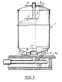
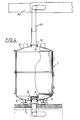
- the ovens used correspond, preferably to ovens comprising a body 1 supported by feet 6 provided with partins 7 for the grip by the fork of a forklift.
- the upper part of the body 1 is closed by a cover 8 with a sleeve 9 in which is guided a chimney 3 connected to a bell 2 movable in said body 1.
- the sleeve 9 is bordered by a circular channel 10 intended to be filled with sand and the lower part of the body 1 comprises a central duct 4 provided with a socket 5 pierced with holes 11 and making it possible to connect the oven to a sheath 12.
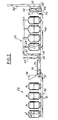
- Figure 1 shows the general layout a charcoal production installation which includes a wood storage area 20, a filling area 21 for the ovens, three charring lines 22, three corresponding drying lines 23, a cooling area 25 where the ovens are stored after carbonization and a station 26 where the ovens are emptied after cooling and where the charcoal is transported to a bagging line.
- Each carbonization line 22 comprises a concrete slab 30 on which the carbonization furnaces 1 stand on the spike, these being by lateral sheaths 12 connected to a central sheath 33 disposed below the concrete slab 30.
- the furnaces of the charring line 22 are therefore under vacuum and the combustion air is sucked through openings in the chimney 3, the wood being lit under the bell 2, the fumes, pyrolignous vapors etc. being sucked into the sheaths 12 and 33 through the openings 11 of the sleeve 5.
- the sheath 33 is connected to an incineration oven 35 which includes a burner 36, a fan 37 and a hopper 38 filled with charcoal dust.
- the fan 36 provides the air necessary for combustion in the oven 35 at the same time as it brings into the latter charcoal dust intended to promote the burning of pyroligneous vapors and to raise the temperature in the oven.
- the outlet of the incineration oven 35 is connected by a line 40 to the suction of a fan 41, the discharge of which opens into a line 42 on which branch lines 43 are connected which cover the sleeves 9 of the ovens of the drying line and whose free edge is inserted in the sand of the canals 10.
- a pipe 45 which being thus connected to the suction of the fan 41 makes it possible to suck in the ambient air to extract the stale air from the room and thus allow the renewal of the air and the ventilation of the local.
- Line 45 also makes it possible to dilute the superheated steam leaving the oven 35 and to lower the temperature thereof.
- the bell 2 In order to allow efficient drying of the wood contained in the ovens of the drying line, the bell 2 is not mounted in them, the superheated steam which is at a temperature of the order of 170 ° C. is sent by the sleeves 9 in the ovens of the drying line pass through the wood and exit through the holes 11 of the sockets 5, the latter being connected to a sheath 46 disposed under the concrete slab 30.
- the superheated steam does not exceed a temperature of around 170 ° C in order to avoid spontaneous ignition of the wood.
- the sheath 46 circulates a vapor whose temperature oscillates between 100 ° C and 150 ° C, this passing through a hydraulic filter 47 before being evacuated outside by a chimney 48.
- the hydraulic filter comprises a pump 49 which draws water into a tank 50 and discharges it into a pipe 51 terminated by a ramp 52 which sends the water in the form of droplets in the upper part of a capacity 53 connected to the cover 50 and connected on the one hand to the sheath 46 and, on the other hand, to the chimney 48.
- the hydraulic filter 47 makes it possible to wash the gases before leaving the atmosphere and to retain the particles in suspension.
- the diagram in FIG. 1 makes it possible to understand the advantage of the installation.
- the ovens are filled with wood and then with a forklift they are transported to a drying line 23. There they are connected to the branches 43.
- the bells 2 Beforehand the ovens of the drying line 23 were moved with a forklift and placed on the line carbonization 22, the bells 2 having been put in place, then, the ovens of the carbonization line 22 are ignited and the superheated vapors are used to dry the wood of the ovens of the drying line as already described above.
- the bells 2 ensure the suffocation of the ovens of the carbonization line, these then being transported from the carbonization line to the cooling area. When cooled the ovens are emptied at station 26.
Description
La présente invention vise une installation de production de charbon de bois.The present invention relates to an installation for producing charcoal.
L'invention se rapporte à une installation dans laquelle on utilise des fours à incinération qui peuvent être déplacés, par exemple, à l'aide d'un chariot élévateur.The invention relates to an installation in which incineration ovens are used which can be moved, for example, using a forklift.
De préférence, mais non exclusivement l'installation prévoit l'utilisation de fours qui permettent l'arrivée d'air comburant par le haut et l'évacuation des vapeurs et fumées par la partie inférieure.Preferably, but not exclusively, the installation provides for the use of ovens which allow the arrival of combustion air from the top and the evacuation of vapors and fumes from the bottom.
On sait, que lors de la phase de carbonisation dans un four il se dégage des vapeurs pyroligneuses, des goudrons, brais, huiles, acides acétiques etc. qui ont un pouvoir calorifique important et qui sont également polluants.We know that during the carbonization phase in an oven, pyroligneous vapors, tar, pitches, oils, acetic acids, etc. are released. which have a high calorific value and which are also polluting.
On sait, également qu'il est préférable avant la carbonisation de procéder à une déshydratation, même partielle du bois.It is also known that it is preferable before carbonization to carry out dehydration, even partial of the wood.
L'un des buts de la présente invention est de réaliser une installation rationnelle de production de charbon de bois qui permet d'éviter le dégagement de vapeurs polluantes et également de procéder à un séchage du bois à carboniser.One of the aims of the present invention is to provide a rational installation for producing charcoal which makes it possible to avoid the release of polluting vapors and also to carry out drying of the wood to be charred.
L'installation, selon l'invention est du type comprenant une ligne de fours de carbonisation, reliés par une gaîne à un four d'incinération avec interposition d'un ventilateur, la sortie du four d'incinération étant reliée à une ligne de fours de séchage du bois à carboniser et est caractérisée en ce que les fours des lignes de carbonisation et de séchage sont identiques et du type comportant à la partie supérieure un manchon d'arrivée d'air comburant et à la partie inférieure une douille d'évacuation des fumées et vapeurs, lesdits fours étant agencés de manière à pouvoir être transportés et, l'installation comprenant une première gaîne pourvue de dérivations destinées à être reliées, chacune d'une manière amovible, à la douille d'un four d'une ligne de fours en action de carbonisation, et reliée au four d'incinération et une conduite pourvue de dérivations reliées, chacune, d'une manière amovible, à un manchon d'un four d'une ligne de fours remplis de bois destiné à être séché avant carbonisation, les douilles des fours de la ligne de séchage étant reliées à une conduite débouchant dans une cheminée.The installation according to the invention is of the type comprising a line of carbonization ovens, connected by a sheath to an incineration oven with the interposition of a fan, the outlet of the incineration oven being connected to a line of ovens for drying the wood to be charred and is characterized in that the furnaces of the charring and drying lines are identical and of the type comprising at the upper part a combustion air intake sleeve and at the lower part a discharge sleeve fumes and vapors, said ovens being arranged so that they can be transported and, the installation comprising a first duct provided with branches intended to be connected, each in a removable manner, to the socket of an oven of a line of furnaces in action of carbonization, and connected to the incineration furnace and a pipe provided with branches connected, each, in a removable manner, to a sleeve of an furnace of a line of furnaces rem plies of wood intended to be dried before carbonization, the sockets of the ovens of the drying line being connected to a pipe opening into a chimney.
Ainsi grâce à l'invention on utilise les vapeurs produites par la combustion et qui sont surchauffées pour déshydrater le bois à carboniser, les gaz rejetés à l'extérieur étant non polluants et ne contenant que de la vapeur d'eau, du gaz carbonique et de l'oxygène. De plus, une telle installation permet un gain de temps très important puisque les fours de la linge de séchage après carbonisation du bois des fours de la ligne de carbonisation remplacent directement ceux-ci.Thus, thanks to the invention, the vapors produced by combustion and which are superheated are used to dehydrate the wood to be carbonized, the gases discharged to the outside being non-polluting and containing only water vapor, carbon dioxide and oxygen. In addition, such an installation allows a very significant time saving since the ovens of the drying linen after carbonization of the wood of the ovens of the carbonization line directly replace these.
Suivant une autre caractéristique, l'installation comprend un filtre inséré entre la conduite reliée aux douilles des fours de la ligne de séchage et la cheminée.According to another characteristic, the installation comprises a filter inserted between the pipe connected to the sockets of the ovens of the drying line and the chimney.
Suivant un détail constructif, le filtre est un filtre hydraulique comprenant une bâche remplie d'eau, une pompe aspirant l'eau de la bâche et la refoulant à travers une rampe de pulvérisation dans une capacité reliée à la bâche et dans la partie inférieure de laquelle débouche la conduite, tandis que sa partie supérieure est reliée à la cheminée.According to a constructive detail, the filter is a hydraulic filter comprising a tarpaulin filled with water, a pump sucking water from the tarpaulin and delivering it through a sprayer boom in a capacity connected to the tarpaulin and in the lower part of which opens the pipe, while its upper part is connected to the chimney.
Suivant encore une caractéristique constructive, le four à incinération comprend un brûleur, un ventilateur et une trémie destinée à être remplie de poussière de charbon de bois. Ainsi dans le four à incinération les vapeurs pyroligneuses sont complètement brûlées, la température étant voisine de 900°C.According to yet another constructive characteristic, the incineration oven comprises a burner, a fan and a hopper intended to be filled with charcoal dust. Thus in the incineration oven the pyroligneous vapors are completely burned, the temperature being close to 900 ° C.
Suivant encore une autre caractéristique, le ventilateur est placé entre le four à incinération, la conduite pourvue de dérivations destinées à être reliées aux manchons des fours de la ligne de séchage et il est prévu une conduite s'ouvrant, d'une part, à l'extérieur et d'autre par, du côté de l'aspiration du ventilateur.According to yet another characteristic, the fan is placed between the incineration oven, the pipe provided with branches intended to be connected to the sleeves of the ovens of the drying line and there is provided a pipe opening, on the one hand, to the outside and on the other hand, on the suction side of the fan.
Grâce à cette caractéristique, on dilue la vapeur surchauffée et on abaisse la température de celle-ci à la sortie du four et on peut, dans le cas où l'installation est située dans un local extraire l'air vicié de celui-ci et réaliser ainsi la ventilation des locaux.Thanks to this characteristic, the superheated steam is diluted and the temperature thereof is lowered at the outlet of the oven and it is possible, in the case where the installation is located in a room, to extract the stale air from it and thus achieve ventilation of the premises.
Enfin, l'installation comprend une aire de stockage du bois à carboniser, une aire de remplissage des fours au moins une ligne de carbonisation et au moins une ligne correspondante de séchage, une aire de refroidissement des fours après carbonisation et au moins un poste de vidage des fours.Finally, the installation comprises a storage area for the wood to be carbonized, an area for filling the ovens with at least one charring line and at least one corresponding drying line, an area for cooling the ovens after charring and at least one emptying the ovens.
On réalise ainsi une installation permettant une bonne productivité.This produces an installation allowing good productivity.
L'invention va maintenant être décrite avec plus de détails en se référant à un mode de réalisation particulier donné à titre d'exemple seulement et représenté aux dessins annexés, dans lesquels:
- Figure 1 montre en plan l'implantation générale de l'installation selon l'invention.
- Figure 2 montre schématiquement en coupe une ligne de carbonisation et la ligne de séchage à laquelle elle est reliée.
- Figure 3 est une vue en élévation partiellement en coupe montrant un four d'une ligne de carbonisation.
- Figure 4 est une vue en élévation partiellement en coupe montrant une four d'une ligne de séchage.
- Figure 1 shows in plan the general layout of the installation according to the invention.
- Figure 2 schematically shows in section a charring line and the drying line to which it is connected.
- Figure 3 is an elevational view partially in section showing an oven of a charring line.
- Figure 4 is an elevational view partially in section showing an oven with a drying line.
Les fours utilisés correspondant, de préférence aux fours comprenant un corps 1 supporté par des pieds 6 munis de partins 7 pour la prise par la fourche d'un chariot élévateur. La partie supérieure du corps 1 est fermée par un couvercle 8 avec un manchon 9 dans lequel est guidée une cheminée 3 reliée à une cloche 2 mobile dans ledit corps 1.The ovens used correspond, preferably to ovens comprising a
Le manchon 9 est bordé par un canal circulaire 10 destiné à être rempli de sable et la partie inférieure du corps 1 comporte un conduit central 4 pourvu d'une douille 5 percée de trous 11 et permettant de relier le four à une gaine 12.The sleeve 9 is bordered by a
La figure 1 montre l'implantation générale d'une installation de production de charbon de bois et qui comprend une aire de stockage du bois 20, une aire de remplissage 21 des fours, trois lignes 22 de carbonisation, trois lignes correspondantes 23 de séchage, une aire de refroidissement 25 où les fours sont stockés après carbonisation et un poste 26 où les fours sont vidés après refroidissement et où le charbon de bois est acheminé vers une chaîne d'ensachage.Figure 1 shows the general layout a charcoal production installation which includes a
Chaque ligne de carbonisation 22 comprend une dalle de béton 30 sur laquelle reposent en épi des fours de carbonisation 1 ceux-ci étant par des gaines latérales 12 reliés à une gaine centrale 33 disposée en dessous de la dalle de béton 30.Each
Les fours de la ligne de carbonisation 22 sont donc en dépression et l'air comburant est aspiré à travers des ouvertures de la cheminée 3, le bois étant allumé sous la cloche 2, les fumées, vapeurs pyroligneuses etc. étant aspirées dans les gaines 12 et 33 à travers les ouvertures 11 de la douille 5.The furnaces of the
La gaine 33 est reliée à un four à incinération 35 qui comprend un brûleur 36, un ventilateur 37 et une trémie 38 remplie de poussière de charbon de bois. Le ventilateur 36 fournit l'air nécessaire à la combustion dans le four 35 en même temps qu'il amène dans ce dernier de la poussière de charbon de bois destinée à favoriser le brûlage des vapeurs pyroligneuses et à faire monter la température dans le four.The
La sortie du four à incinération 35 est reliée par une conduite 40 à l'aspiration d'un ventilateur 41 dont le refoulement débouche dans une conduite 42 sur laquelle sont branchées des dérivations 43 qui viennent coiffer les manchons 9 des fours de la ligne de séchage et dont le bord libre s'insère dans le sable des canaux 10.The outlet of the
Sur la conduite 40 est branchée une conduite 45 qui étant ainsi reliée à l'aspiration du ventilateur 41 permet d'aspirer le l'air ambiant pour extraire l'air vicié du local et ainsi permettre le renouvellement de l'air et la ventilation des locaux. La conduite 45 permet également de diluer la vapeur surchauffée sortant du four 35 et d'abaisser la température de celle-ci.On the
Afin de permettre un séchage efficace du bois contenu dans les fours de la ligne de séchage, la cloche 2 n'est pas montée dans ceux-ci, la vapeur surchaffée qui est à une température de l'ordre de 170°C est envoyée par les manchons 9 dans les fours de la ligne de séchage traverse le bois et ressort par les trous 11 des douilles 5, celles-ci étant reliées à une gaine 46 disposée sous la dalle de béton 30.In order to allow efficient drying of the wood contained in the ovens of the drying line, the
Il est important que la vapeur surchaffée ne dépasse pas une température de l'ordre de 170°C afin d'éviter les inflammations spontanées du bois.It is important that the superheated steam does not exceed a temperature of around 170 ° C in order to avoid spontaneous ignition of the wood.
Dans la gaine 46 circule une vapeur dont la température oscille entre 100°C et 150°C, celle-ci traversant un filtre hydraulique 47 avant d'être évacuée à l'extérieur par une cheminée 48.In the sheath 46 circulates a vapor whose temperature oscillates between 100 ° C and 150 ° C, this passing through a hydraulic filter 47 before being evacuated outside by a
Le filtre hydraulique comprend une pompe 49 qui aspire l'eau dans une bâche 50 et refoule celle-ci dans un tuyau 51 terminé par une rampe 52 qui envoie l'eau sous forme de gouttelettes dans la partie supérieure d'une capacité 53 reliée à la bâche 50 et reliée d'une part à la gaine 46 et, d'autre part, à la cheminée 48.The hydraulic filter comprises a pump 49 which draws water into a
Le filtre hydraulique 47 permet de laver les gaz avant la sortie dans l'atmosophère et de retenir les particules en suspension.The hydraulic filter 47 makes it possible to wash the gases before leaving the atmosphere and to retain the particles in suspension.
Une telle installation permet une production rationnelle, n'est pas polluante et offre de grands avantages de productivité.Such an installation allows rational production, is not polluting and offers great productivity advantages.
Le schéma de la figure 1 permet de bien comprendre l'intérêt de l'installation. Les fours sont remplis de bois puis avec un chariot élévateur ils sont transportés à une ligne de séchage 23. Là ils sont branchés aux dérivations 43. Préalablement les fours de la ligne de séchage 23 ont été déplacés avec un chariot élévateur et placés sur la ligne de carbonisation 22, les cloches 2 ayant été mises en place, puis, les fours de la ligne de carbonisation 22 sont allumés et on utilise les vapeurs surchauffées pour sécher le bois des fours de la ligne de séchage comme déjà exposé plus haut. En fin de carbonisation les cloches 2 assurent l'étouffement des fours de la ligne de carbonisation, ceux-ci étant alors transportés depuis la ligne de carbonisation à l'aire 25 de refroidissement. Lorsqu'ils sont refroidis les fours sont vidés au poste 26.The diagram in FIG. 1 makes it possible to understand the advantage of the installation. The ovens are filled with wood and then with a forklift they are transported to a
Bien entendu, l'invention n'est pas limitée au mode de réalisation qui vient d'être décrit en représenté. On pourra y apporter de nombreuses modifications de détail sans sortir pour cela du cadre de l'invention.Of course, the invention is not limited to the embodiment which has just been described in the illustration. Many detailed modifications can be made without departing from the scope of the invention.
Claims (6)
Applications Claiming Priority (3)
| Application Number | Priority Date | Filing Date | Title |
|---|---|---|---|
| FR8710540 | 1987-07-24 | ||
| FR8710540A FR2618448B1 (en) | 1987-07-24 | 1987-07-24 | CHARCOAL PRODUCTION FACILITY |
| EP88400764A EP0335044A1 (en) | 1987-07-24 | 1988-03-29 | Plant for the production of charcoal |
Publications (2)
| Publication Number | Publication Date |
|---|---|
| EP0300925A1 EP0300925A1 (en) | 1989-01-25 |
| EP0300925B1 true EP0300925B1 (en) | 1991-01-02 |
Family
ID=39683825
Family Applications (2)
| Application Number | Title | Priority Date | Filing Date |
|---|---|---|---|
| EP88400764A Withdrawn EP0335044A1 (en) | 1987-07-24 | 1988-03-29 | Plant for the production of charcoal |
| EP88401934A Expired - Lifetime EP0300925B1 (en) | 1987-07-24 | 1988-07-25 | Installation for the production of charcoal |
Family Applications Before (1)
| Application Number | Title | Priority Date | Filing Date |
|---|---|---|---|
| EP88400764A Withdrawn EP0335044A1 (en) | 1987-07-24 | 1988-03-29 | Plant for the production of charcoal |
Country Status (4)
| Country | Link |
|---|---|
| EP (2) | EP0335044A1 (en) |
| DE (1) | DE3861361D1 (en) |
| ES (1) | ES2020337B3 (en) |
| FR (1) | FR2618448B1 (en) |
Families Citing this family (3)
| Publication number | Priority date | Publication date | Assignee | Title |
|---|---|---|---|---|
| KR0141512B1 (en) * | 1994-06-14 | 1998-07-15 | 마재열 | Advanced operating travelling system of bicycle |
| GB9723782D0 (en) * | 1997-11-12 | 1998-01-07 | Webster Robin | Double oven retort |
| CN108359508A (en) * | 2018-03-16 | 2018-08-03 | 应佩荣 | The bamboo and wood charcoal producing technique of charcoal kiln charing is reloaded into after bamboo timber stoving |
Family Cites Families (5)
| Publication number | Priority date | Publication date | Assignee | Title |
|---|---|---|---|---|
| FR577471A (en) * | 1924-02-20 | 1924-09-05 | Horizontal mobile retort furnace for continuous carbonization of wood in a forest in isolation | |
| FR599916A (en) * | 1925-04-24 | 1926-01-25 | Portable device for carbonization of wood in the forest | |
| FR883470A (en) * | 1941-06-11 | 1943-07-06 | Wood and cellulosic distillation furnace with recovery of by-products and drying oven | |
| US4280878A (en) * | 1979-10-30 | 1981-07-28 | Sprenger Gerald E | Structure and process for reclaiming heat from charcoal production facility |
| FR2586031A1 (en) * | 1985-08-06 | 1987-02-13 | Sennesael Etienne | Self-drying and cooling carbonisation unit |
-
1987
- 1987-07-24 FR FR8710540A patent/FR2618448B1/en not_active Expired - Fee Related
-
1988
- 1988-03-29 EP EP88400764A patent/EP0335044A1/en not_active Withdrawn
- 1988-07-25 ES ES88401934T patent/ES2020337B3/en not_active Expired - Lifetime
- 1988-07-25 DE DE8888401934T patent/DE3861361D1/en not_active Expired - Lifetime
- 1988-07-25 EP EP88401934A patent/EP0300925B1/en not_active Expired - Lifetime
Also Published As
| Publication number | Publication date |
|---|---|
| ES2020337B3 (en) | 1991-08-01 |
| FR2618448A1 (en) | 1989-01-27 |
| EP0335044A1 (en) | 1989-10-04 |
| EP0300925A1 (en) | 1989-01-25 |
| FR2618448B1 (en) | 1994-04-08 |
| DE3861361D1 (en) | 1991-02-07 |
Similar Documents
| Publication | Publication Date | Title |
|---|---|---|
| EP0055261B1 (en) | Method and device for the treatment of wet product | |
| EP0152317B1 (en) | Boiler for wood with a preheating chamber for the fuel | |
| FR2511027A1 (en) | INSTALLATION FOR DRYING, PYROLYSIS AND, WHERE APPROPRIATE, FOR GASIFICATION, AND METHOD FOR ITS IMPLEMENTATION | |
| EP0300925B1 (en) | Installation for the production of charcoal | |
| EA004014B1 (en) | Method of assembling a portable kiln, method of using a portable kiln, a portable apparatus | |
| CA2240532A1 (en) | Method and plant for treating solid waste products by thermolysis | |
| EP0893651B1 (en) | Burner for liquid and gaseous fuel with low nitric oxyde emission | |
| CN208090674U (en) | Continous way high temperature garbage pyrocrack furnace | |
| FR2583427A1 (en) | Process for the manufacture of charcoal, device for its use and products obtained by this process | |
| CA2101917A1 (en) | Device for extracting and storing residues, and corresponding filter cartridge | |
| FR2995666A1 (en) | Hearth for combusting e.g. woody solid fuel elements, has pot whose bottom is completely closed to form base chamber, and lateral wall provided with ring of openings to form primary combustion chamber for base of solid fuel elements | |
| EP0330789A1 (en) | Process and apparatus for producing charcoal | |
| FR2465173A1 (en) | Combined incinerator and pre dryer - has dryer supplied with hot gases from incinerator exhaust | |
| CN108240626B (en) | Continous way high temperature garbage pyrocrack furnace | |
| EP0841519A1 (en) | Process and installation for the treatment by combustion of waste, and for heat recovery | |
| CN107842857A (en) | Gasification, and combustion waste incinerator | |
| FR2765585A1 (en) | Charcoal production by carbonisation of wood | |
| CN207279651U (en) | A kind of burned waste gas device | |
| JP3057364B2 (en) | Incinerator | |
| FR2535026A1 (en) | Boiler using wood or other solid combustible materials | |
| EP0214010A1 (en) | Burner with a gasifying stage for a heating device, and heating device comprising such a burner | |
| JPS59145282A (en) | Preparation of charcoal and equipment therefor | |
| FR2505029A2 (en) | Furnace for burning rubbish - has inclined sealed rotating chamber fed with gas and rubbish simultaneously | |
| US1141747A (en) | Apparatus for burning stumps. | |
| FR2514073A1 (en) | PYROLYSIS INSTALLATION, IN PARTICULAR FOR PLANT WASTES SUCH AS HULLS OR ENVELOPES OF SEEDS, AND METHOD OF OPERATION |
Legal Events
| Date | Code | Title | Description |
|---|---|---|---|
| PUAI | Public reference made under article 153(3) epc to a published international application that has entered the european phase |
Free format text: ORIGINAL CODE: 0009012 |
|
| AK | Designated contracting states |
Kind code of ref document: A1 Designated state(s): BE DE ES IT |
|
| 17P | Request for examination filed |
Effective date: 19890404 |
|
| 17Q | First examination report despatched |
Effective date: 19891222 |
|
| ITF | It: translation for a ep patent filed |
Owner name: STUDIO D'ORIO |
|
| GRAA | (expected) grant |
Free format text: ORIGINAL CODE: 0009210 |
|
| AK | Designated contracting states |
Kind code of ref document: B1 Designated state(s): BE DE ES IT |
|
| REF | Corresponds to: |
Ref document number: 3861361 Country of ref document: DE Date of ref document: 19910207 |
|
| PLBE | No opposition filed within time limit |
Free format text: ORIGINAL CODE: 0009261 |
|
| STAA | Information on the status of an ep patent application or granted ep patent |
Free format text: STATUS: NO OPPOSITION FILED WITHIN TIME LIMIT |
|
| 26N | No opposition filed | ||
| PGFP | Annual fee paid to national office [announced via postgrant information from national office to epo] |
Ref country code: BE Payment date: 19930730 Year of fee payment: 6 |
|
| PGFP | Annual fee paid to national office [announced via postgrant information from national office to epo] |
Ref country code: ES Payment date: 19930731 Year of fee payment: 6 |
|
| PGFP | Annual fee paid to national office [announced via postgrant information from national office to epo] |
Ref country code: DE Payment date: 19930806 Year of fee payment: 6 |
|
| PG25 | Lapsed in a contracting state [announced via postgrant information from national office to epo] |
Ref country code: ES Free format text: LAPSE BECAUSE OF NON-PAYMENT OF DUE FEES Effective date: 19940726 |
|
| PG25 | Lapsed in a contracting state [announced via postgrant information from national office to epo] |
Ref country code: BE Effective date: 19940731 |
|
| BERE | Be: lapsed |
Owner name: DEVALLET ANDRE Effective date: 19940731 |
|
| PG25 | Lapsed in a contracting state [announced via postgrant information from national office to epo] |
Ref country code: DE Effective date: 19950401 |
|
| REG | Reference to a national code |
Ref country code: ES Ref legal event code: FD2A Effective date: 20020603 |
|
| PG25 | Lapsed in a contracting state [announced via postgrant information from national office to epo] |
Ref country code: IT Free format text: LAPSE BECAUSE OF NON-PAYMENT OF DUE FEES;WARNING: LAPSES OF ITALIAN PATENTS WITH EFFECTIVE DATE BEFORE 2007 MAY HAVE OCCURRED AT ANY TIME BEFORE 2007. THE CORRECT EFFECTIVE DATE MAY BE DIFFERENT FROM THE ONE RECORDED. Effective date: 20050725 |