EP0300899B1 - Filter device for peridural anaesthesia - Google Patents
Filter device for peridural anaesthesia Download PDFInfo
- Publication number
- EP0300899B1 EP0300899B1 EP88401876A EP88401876A EP0300899B1 EP 0300899 B1 EP0300899 B1 EP 0300899B1 EP 88401876 A EP88401876 A EP 88401876A EP 88401876 A EP88401876 A EP 88401876A EP 0300899 B1 EP0300899 B1 EP 0300899B1
- Authority
- EP
- European Patent Office
- Prior art keywords
- membrane
- filter device
- filter
- bore
- support surface
- Prior art date
- Legal status (The legal status is an assumption and is not a legal conclusion. Google has not performed a legal analysis and makes no representation as to the accuracy of the status listed.)
- Expired - Lifetime
Links
Images


Classifications
-
- A—HUMAN NECESSITIES
- A61—MEDICAL OR VETERINARY SCIENCE; HYGIENE
- A61M—DEVICES FOR INTRODUCING MEDIA INTO, OR ONTO, THE BODY; DEVICES FOR TRANSDUCING BODY MEDIA OR FOR TAKING MEDIA FROM THE BODY; DEVICES FOR PRODUCING OR ENDING SLEEP OR STUPOR
- A61M5/00—Devices for bringing media into the body in a subcutaneous, intra-vascular or intramuscular way; Accessories therefor, e.g. filling or cleaning devices, arm-rests
- A61M5/14—Infusion devices, e.g. infusing by gravity; Blood infusion; Accessories therefor
- A61M5/165—Filtering accessories, e.g. blood filters, filters for infusion liquids
-
- A—HUMAN NECESSITIES
- A61—MEDICAL OR VETERINARY SCIENCE; HYGIENE
- A61M—DEVICES FOR INTRODUCING MEDIA INTO, OR ONTO, THE BODY; DEVICES FOR TRANSDUCING BODY MEDIA OR FOR TAKING MEDIA FROM THE BODY; DEVICES FOR PRODUCING OR ENDING SLEEP OR STUPOR
- A61M19/00—Local anaesthesia; Hypothermia
-
- A—HUMAN NECESSITIES
- A61—MEDICAL OR VETERINARY SCIENCE; HYGIENE
- A61M—DEVICES FOR INTRODUCING MEDIA INTO, OR ONTO, THE BODY; DEVICES FOR TRANSDUCING BODY MEDIA OR FOR TAKING MEDIA FROM THE BODY; DEVICES FOR PRODUCING OR ENDING SLEEP OR STUPOR
- A61M5/00—Devices for bringing media into the body in a subcutaneous, intra-vascular or intramuscular way; Accessories therefor, e.g. filling or cleaning devices, arm-rests
- A61M5/14—Infusion devices, e.g. infusing by gravity; Blood infusion; Accessories therefor
- A61M5/165—Filtering accessories, e.g. blood filters, filters for infusion liquids
- A61M2005/1657—Filter with membrane, e.g. membrane, flat sheet type infusion filter
Definitions
- the present invention concerns a filter device for peridural or epidural anaesthesia.
- This type of local/regional anaesthesia is increasingly used nowadays to treat pain, especially for chronic illnesses, surgical operations and childbirth.
- the practioner has first to find the peridural space containing the rachidian nerve to be anaesthetised by inserting the tip of a bevelled peridural needle upwardly between the second and third lumbar vertebrae.
- the tip enters the peridural space delimited by the dura mater and the walls of the rachidian canal into which a flexible catheter will be introduced through the needle to enable the anaesthetic to be injected.
- a first type consists of a circular filter membrane the edge of which is welded to a plastics material casing in two parts, placed on either side of the membrane; each of these two parts comprises an enclosure with an inlet or outlet orifice the axis of which is perpendicular to the plane of the filter membrane.
- a second type of filter has been launched onto the market which differs from the previous type in that the axes of the inlet and outlet orifices leading to and from the spaces situated on either side of the filter membrane are not perpendicular but rather parallel to the plane of the membrane which is itself parallel to the filter casing.
- this kind of arrangement means that only one side of the filter, that opposite the side from which the membrane access orifices project, can be attached to the body of the patient.
- both orifices are situated on the same side of the membrane there has to be provided for one of them a U-shaped passage providing access to the opposite side of the membrane, which requires the presence of a third plastics material member, of circular ring shape, to delimit this access channel.
- a structure of this kind with three plastics material components increases the unit cost of manufacturing this type of filter and also, because of the U-shaped channel providing access to one side of the membrane, produces a head loss which reduces the sensitivity of the equipment when used by the anaesthetist.
- GB-A-2,043,478 discloses a filter device wherein a membrane is sealed along a groove formed in the annular shoulder of a shallow disc-shaped plastic base having an inlet and an outlet provided on opposite sides of the shoulder so that fluid passing through the filter device must pass through the membrane and a substantially flat cap is applied to the plastic base for completing the filter device.
- a substantially flat cap is applied to the plastic base for completing the filter device.
- An object of the present invention is a filter device whose structure makes it possible to overcome these disadvantages.
- the flat, reversible and disposable filter device in accordance with the invention for peridural anaesthesia comprises a rigid casing consisting of only two plastics material parts which are welded to each other and disposed on either side of a filter membrane, each plastics material part comprising an inlet or outlet bore communicating with a space comprising membrane support members and one of the two support surfaces for the surface membrane is free of any relief members projecting beyond said support surface.
- This filter device is characterised by the fact that the membrane support members of each of the two plastics material parts have a circular support surface defining a plane at an acute angle to the axes of the inlet and outlet bores.
- the access orifices situated on either side of the membrane can be disposed on the filter device without them projecting beyond the edges of the membrane.
- a structure of this kind makes the filter device entirely reversible so that it can be placed on the body of the patient either way up, which eliminates the possibility of positioning errors.
- one of the membrane support surfaces provided in one of the two plastics material parts does not comprise any relief members projecting beyond this surface makes it possible to weld the membrane to this surface using an automatic device working from a continuous strip of filter material from which the membrane is cut out.
- the filter device for peridural anaesthesia shown in figures 1 and 2 comprises a casing consisting of two plastics material parts 1 and 2 between which is disposed a filter membrane 3.
- the lower part or base 1 is shown in figures 3 and 4 and the upper part or lid 2 is shown in figures 5 and 6.
- the base 1 comprises a substantially cylindrical vertical wall 16 having a lower and 15 situated in a horizontal plane and an upper end 18 situated in a plane at an acute angle alpha to the horizontal.
- This angle alpha is preferably between 5 and 15° and in the example shown in figures 1 through 6 is equal to 10°.
- the base 1 also comprises a bottom 17 the plane of which is at the same acute angle as the upper end 18 of the wall 16 so as to form a female member.
- the upper surface of the bottom 17, which forms an inclined plane, comprises a plane peripheral ring 19 delimited by an external circular groove 20 and an internal circular groove 21.
- All of the surface located inside the plane ring 19 comprises parallel longitudinal grooves 22 which open into the internal groove 21 and are delimited by parallel longitudinal ribs 23.
- the tops of the ribs 23 are in substantially the same plane as the plane peripheral ring 19 so as to form a lower inclined support surface for the filter membrane 3.
- the space defined by the internal circular groove 21 and the longitudinal grooves 22 constitutes the sole means giving access to the lower surface of the filter membrane 3.
- Such a structure allows the air to escape through the filter membrane, when the liquid is fed, before the membrane, wet by the liquid, becomes gas-tight.
- the base 1 also comprises an outlet bore 5 the axis of which, as shown in figure 3, is parallel to the plane of the lower end 15 and which is conical in shape with a double external screwthread forming a conventional "LUER" type connector as used for catheters.
- the bore 5 passes through the wall 16 and communicates at right angles with a feed channel 24 which opens directly into the internal circular groove 21.
- the feed channel 24 preferably has a U-shaped tranverse cross-section (see figure 4) in which the base of the U opens into the groove 21 and the two branches of the U, the length of which can increase as said section moves closer to the groove 21, open into two parallel longitudinal grooves 22.
- the upper part or lid 2 of the filter device in accordance with the invention comprises, as shown in figure 5, a vertical wall 25 having a plane upper end 26 situated in a horizontal plane and a lower end 27 situated in a plane at the same acute angle alpha to the horizontal as the base 1.
- the lid 2 also comprises a bottom 28 the plane of which is at the same acute angle as the lower end 27 of the wall 25 and which is joined to the latter by a substantially cylindral wall 29 the diameter of which is slightly less than that of the wall 25 so as to form a male member the dimensions of which correspond approximately to the female member of the base 1.
- this vertical cylindrical wall 29 is such that the lower surface of the bottom 28 does not comprise any relief members projecting beyond this surface.
- the lower surface of the bottom 28, which forms an inclined plane comprises a plane peripheral ring 30 delimited by the vertical wall 29 and by an internal circular groove 31. All of the surface situated inside the plane ring 30 comprises parallel longitudinal grooves 32 which open into the internal grooves 31 and are delimited by parallel longitudinal ribs 33.
- tops of the ribs 33 are in substantially the same plane as the plane peripheral rings 30 so as to form an upper inclined support surface for the filter membrane 3.
- the axial rib 23 of the base 1 and the axial rib 33 of the lid 2 are situated in the same plane and extend in the same direction as the axes of the inlet bore 4 and the outlet bore 5, so as to facilitate the flow of the liquid to be filtered.
- the space defined by the internal circular groove 31 and the longitudinal grooves 32 constitutes the sole means giving access to the upper surface of the filter membrane 3.
- This structure of the upper inclined support surface for the filter membrane in the lid 2 is quite similar to the one of lower inclined support surface for the membrane in the base 1.
- the lid 2 also comprises an inlet bore 4 the axis of which, as shown in figure 5, is parallel to the plane of the upper end 26 and which is conical in shape to serve as a connector for the end of a syringe.
- the bore 4 passes through the wall 25 and communicates at right angles with a feed channel 34 which opens directly into the internal circular groove 31.
- this feed channel 34 preferably has a U-shaped transverse cross-section (see figure 6) in which the base of the U opens into the groove 31 and the two branches of the U, the length of which can increase towards the groove 31, open into two parallel longitudinal grooves 32.
- the circular filter membrane 3 is welded to the plane peripheral ring 30 of the lid 2 and this welding may easily be performed by automatic means working from a continuous strip of filter material, given the absence of any relief members projecting beyond the lower surface of the bottom 28.
- the base 1 is placed and aligned on the lid 2 so that these two plastics members, which constitute the casing of the filter device in accordance with the invention, can be ultrasonically welded to each other in their final position along the cylindrical wall 29.
- the filter membrane 3 is sandwiched between the ribs 23 and 33, the tops of which are supporting it on each side. Due to this welding and these support members, located as well upstream as downstream, the filter membrane is maintained flat and cannot loose its shape, rendering the filter device perfectly reversible.
- the materials of the filter membrane 3 and the plastics material parts 1 and 2 are conventional and do not form any part of the present invention.
- the filter membrane which generally has a pore diameter between 0.1 and 0.5 microns, may be made from a cellulose ester, a polyolefin or polytetrafluorethylene and the plastics material of the envelope may be polyvinylchloride, a polyolefin or styrene-acrylonitrile resin.
- the filter device according to the invention is particularly suitable for hydrophilic filter membranes and allows notably the use of such membranes which are very brittle, such as those made of cellulosic esters.
- the path of the filtered liquid is designed to minimise head losses and to obtain an average flowrate by gravity which is higher than that obtained with filter devices previously available through commercial channels for peridural anaesthesia with the same filter membrane surface area and characteristics.
- the filter unit due to its structure, may operate, whatever be its position, whether horizontal, vertical or other and it can be used therefore directly in contact with a patient, without to be maintained compulsorily in a vertical position.
Description
- The present invention concerns a filter device for peridural or epidural anaesthesia.
- This type of local/regional anaesthesia is increasingly used nowadays to treat pain, especially for chronic illnesses, surgical operations and childbirth.
- The practioner has first to find the peridural space containing the rachidian nerve to be anaesthetised by inserting the tip of a bevelled peridural needle upwardly between the second and third lumbar vertebrae. The tip enters the peridural space delimited by the dura mater and the walls of the rachidian canal into which a flexible catheter will be introduced through the needle to enable the anaesthetic to be injected.
- To prevent transfer of the anaesthetic causing bacterial or microparticle contamination (glass, rubber, etc), it is essential to use a filter device between the syringe and the catheter.
- Two different types of filter device have been used hitherto for peridural anaesthesia.
- A first type consists of a circular filter membrane the edge of which is welded to a plastics material casing in two parts, placed on either side of the membrane; each of these two parts comprises an enclosure with an inlet or outlet orifice the axis of which is perpendicular to the plane of the filter membrane.
- Although this first type of filter was entirely satisfactory from the technical point of view, it did not suit in practice because of its pear-shaped structure, which prevented it being attached conveniently and comfortably to the body of the patient under treatment.
- A second type of filter has been launched onto the market which differs from the previous type in that the axes of the inlet and outlet orifices leading to and from the spaces situated on either side of the filter membrane are not perpendicular but rather parallel to the plane of the membrane which is itself parallel to the filter casing.
- However, in this second type of filter the inlet and outlet orifices project from the same side of the membrane, which has a two-fold disadvantage.
- On the one hand, this kind of arrangement means that only one side of the filter, that opposite the side from which the membrane access orifices project, can be attached to the body of the patient.
- On the other hand as both orifices are situated on the same side of the membrane there has to be provided for one of them a U-shaped passage providing access to the opposite side of the membrane, which requires the presence of a third plastics material member, of circular ring shape, to delimit this access channel. A structure of this kind with three plastics material components increases the unit cost of manufacturing this type of filter and also, because of the U-shaped channel providing access to one side of the membrane, produces a head loss which reduces the sensitivity of the equipment when used by the anaesthetist.
- At last, GB-A-2,043,478 discloses a filter device wherein a membrane is sealed along a groove formed in the annular shoulder of a shallow disc-shaped plastic base having an inlet and an outlet provided on opposite sides of the shoulder so that fluid passing through the filter device must pass through the membrane and a substantially flat cap is applied to the plastic base for completing the filter device. In this prior device, wherein one support surface for the filter membrane is free of any relief member projecting beyond the support surface, the membrane, which is not in contact with the substantially flat cap, is supported only on one side and the filter device is therefore not reversible.
- An object of the present invention is a filter device whose structure makes it possible to overcome these disadvantages.
- The flat, reversible and disposable filter device in accordance with the invention for peridural anaesthesia comprises a rigid casing consisting of only two plastics material parts which are welded to each other and disposed on either side of a filter membrane, each plastics material part comprising an inlet or outlet bore communicating with a space comprising membrane support members and one of the two support surfaces for the surface membrane is free of any relief members projecting beyond said support surface.
- This filter device is characterised by the fact that the membrane support members of each of the two plastics material parts have a circular support surface defining a plane at an acute angle to the axes of the inlet and outlet bores.
- By virtue of the inclination of the filter membrane, the access orifices situated on either side of the membrane can be disposed on the filter device without them projecting beyond the edges of the membrane.
- A structure of this kind makes the filter device entirely reversible so that it can be placed on the body of the patient either way up, which eliminates the possibility of positioning errors.
- Also the fact that one of the membrane support surfaces provided in one of the two plastics material parts does not comprise any relief members projecting beyond this surface makes it possible to weld the membrane to this surface using an automatic device working from a continuous strip of filter material from which the membrane is cut out.
- Finally the circular shape of the filter membrane support surfaces and the inclination of the membrane relative to the direction of movement of the filtered liquid make it possible to avoid the formation of any air pocket a source of bubbles which can cause unwanted disturbance to the flow of the fluid after it passes through the filter device in accordance with the invention.
- The present invention will now be described in one specific embodiment shown in the appended drawings in which:
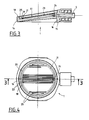
- ― figure 1 is a view of the filter device in accordance with the invention in cross-section on the line 1-1 in figure 2;
- ― figure 2 is a plan view of the device from figure 1;
- ― figures 3 and 4 are respectively a view in cross-section on the line 3-3 in figure 4 and a plan view of the lower part of the plastics material casing; and
- ― figures 5 and 6 are respectively a view in cross-section on the line 5-5 in figure 6 including the filter membrane and a bottom view without the filter membrane of the upper part of the plastics material casing of the filter device in accordance with the invention.
- The filter device for peridural anaesthesia shown in figures 1 and 2 comprises a casing consisting of two
plastics material parts filter membrane 3. - The lower part or
base 1 is shown in figures 3 and 4 and the upper part orlid 2 is shown in figures 5 and 6. - As shown in figure 3 in particular the
base 1 comprises a substantially cylindricalvertical wall 16 having a lower and 15 situated in a horizontal plane and anupper end 18 situated in a plane at an acute angle alpha to the horizontal. - This angle alpha is preferably between 5 and 15° and in the example shown in figures 1 through 6 is equal to 10°.
- The
base 1 also comprises abottom 17 the plane of which is at the same acute angle as theupper end 18 of thewall 16 so as to form a female member. - The upper surface of the
bottom 17, which forms an inclined plane, comprises a planeperipheral ring 19 delimited by an externalcircular groove 20 and an internalcircular groove 21. - All of the surface located inside the
plane ring 19 comprises parallellongitudinal grooves 22 which open into theinternal groove 21 and are delimited by parallellongitudinal ribs 23. - The tops of the
ribs 23 are in substantially the same plane as the planeperipheral ring 19 so as to form a lower inclined support surface for thefilter membrane 3. - The space defined by the internal
circular groove 21 and thelongitudinal grooves 22 constitutes the sole means giving access to the lower surface of thefilter membrane 3. - Such a structure allows the air to escape through the filter membrane, when the liquid is fed, before the membrane, wet by the liquid, becomes gas-tight.
- This disposition allows, due to the absence of any chamber in permanent contact with the surface of the filter membrane, to avoid the formation of an air bubble, known under the name of air lock, which reduces the filtering surface available and consequently the efficiency of the filter device.
- The
base 1 also comprises an outlet bore 5 the axis of which, as shown in figure 3, is parallel to the plane of thelower end 15 and which is conical in shape with a double external screwthread forming a conventional "LUER" type connector as used for catheters. - The
bore 5 passes through thewall 16 and communicates at right angles with afeed channel 24 which opens directly into the internalcircular groove 21. - The
feed channel 24 preferably has a U-shaped tranverse cross-section (see figure 4) in which the base of the U opens into thegroove 21 and the two branches of the U, the length of which can increase as said section moves closer to thegroove 21, open into two parallellongitudinal grooves 22. - The upper part or
lid 2 of the filter device in accordance with the invention comprises, as shown in figure 5, avertical wall 25 having a planeupper end 26 situated in a horizontal plane and alower end 27 situated in a plane at the same acute angle alpha to the horizontal as thebase 1. - The
lid 2 also comprises abottom 28 the plane of which is at the same acute angle as thelower end 27 of thewall 25 and which is joined to the latter by a substantiallycylindral wall 29 the diameter of which is slightly less than that of thewall 25 so as to form a male member the dimensions of which correspond approximately to the female member of thebase 1. - The length of this vertical
cylindrical wall 29 is such that the lower surface of thebottom 28 does not comprise any relief members projecting beyond this surface. - The lower surface of the
bottom 28, which forms an inclined plane (see figure 5), comprises a planeperipheral ring 30 delimited by thevertical wall 29 and by an internalcircular groove 31. All of the surface situated inside theplane ring 30 comprises parallellongitudinal grooves 32 which open into theinternal grooves 31 and are delimited by parallellongitudinal ribs 33. - The tops of the
ribs 33 are in substantially the same plane as the planeperipheral rings 30 so as to form an upper inclined support surface for thefilter membrane 3. - In the embodiment shown in figures 1 through 6 the
axial rib 23 of thebase 1 and theaxial rib 33 of thelid 2 are situated in the same plane and extend in the same direction as the axes of the inlet bore 4 and the outlet bore 5, so as to facilitate the flow of the liquid to be filtered. - The space defined by the internal
circular groove 31 and thelongitudinal grooves 32 constitutes the sole means giving access to the upper surface of thefilter membrane 3. - This structure of the upper inclined support surface for the filter membrane in the
lid 2 is quite similar to the one of lower inclined support surface for the membrane in thebase 1. - The
lid 2 also comprises an inlet bore 4 the axis of which, as shown in figure 5, is parallel to the plane of theupper end 26 and which is conical in shape to serve as a connector for the end of a syringe. - The bore 4 passes through the
wall 25 and communicates at right angles with afeed channel 34 which opens directly into the internalcircular groove 31. - Like the
channel 24, thisfeed channel 34 preferably has a U-shaped transverse cross-section (see figure 6) in which the base of the U opens into thegroove 31 and the two branches of the U, the length of which can increase towards thegroove 31, open into two parallellongitudinal grooves 32. - This particular shape of the transverse cross-section of the
channel 24 of thebase 1 and thechannel 34 of thelid 2 makes it possible to mould these twoparts - As shown in figure 5, the
circular filter membrane 3 is welded to the planeperipheral ring 30 of thelid 2 and this welding may easily be performed by automatic means working from a continuous strip of filter material, given the absence of any relief members projecting beyond the lower surface of thebottom 28. - After welding the
filter membrane 3 to therings 30, thebase 1 is placed and aligned on thelid 2 so that these two plastics members, which constitute the casing of the filter device in accordance with the invention, can be ultrasonically welded to each other in their final position along thecylindrical wall 29. - After this welding, the
filter membrane 3 is sandwiched between theribs - The materials of the
filter membrane 3 and theplastics material parts - However, the filter membrane, which generally has a pore diameter between 0.1 and 0.5 microns, may be made from a cellulose ester, a polyolefin or polytetrafluorethylene and the plastics material of the envelope may be polyvinylchloride, a polyolefin or styrene-acrylonitrile resin.
- The filter device according to the invention is particularly suitable for hydrophilic filter membranes and allows notably the use of such membranes which are very brittle, such as those made of cellulosic esters.
- It should be noted that all the welds necessary for assembling the claimed filter device are performed externally of the filter surface, which makes it possible to avoid burrs or molten material debris interfering with the filtration process.
- Also, the path of the filtered liquid is designed to minimise head losses and to obtain an average flowrate by gravity which is higher than that obtained with filter devices previously available through commercial channels for peridural anaesthesia with the same filter membrane surface area and characteristics.
- These enhanced properties are obtained by virtue of a structure that is simple to manufacture as there are fewer component parts to be welded together, safer in use as the sensitivity that the anaesthetist requires is retained and more practical as it is more compact and entirely reversible.
- The filter unit, due to its structure, may operate, whatever be its position, whether horizontal, vertical or other and it can be used therefore directly in contact with a patient, without to be maintained compulsorily in a vertical position.
Claims (9)
Applications Claiming Priority (2)
| Application Number | Priority Date | Filing Date | Title |
|---|---|---|---|
| FR8710479 | 1987-07-23 | ||
| FR8710479A FR2618338B1 (en) | 1987-07-23 | 1987-07-23 | FILTRATION ASSEMBLY FOR PERIDURAL ANESTHESIA |
Publications (2)
| Publication Number | Publication Date |
|---|---|
| EP0300899A1 EP0300899A1 (en) | 1989-01-25 |
| EP0300899B1 true EP0300899B1 (en) | 1991-09-18 |
Family
ID=9353495
Family Applications (1)
| Application Number | Title | Priority Date | Filing Date |
|---|---|---|---|
| EP88401876A Expired - Lifetime EP0300899B1 (en) | 1987-07-23 | 1988-07-20 | Filter device for peridural anaesthesia |
Country Status (4)
| Country | Link |
|---|---|
| US (1) | US4902415A (en) |
| EP (1) | EP0300899B1 (en) |
| DE (1) | DE3864934D1 (en) |
| FR (1) | FR2618338B1 (en) |
Families Citing this family (7)
| Publication number | Priority date | Publication date | Assignee | Title |
|---|---|---|---|---|
| DE3804429A1 (en) * | 1988-02-12 | 1989-08-24 | Schleicher & Schuell Gmbh | DISPOSABLE FILTER |
| FR2748953B1 (en) * | 1996-05-24 | 1998-10-02 | Millipore Sa | ELLIPSE-SHAPED FILTRATION UNIT |
| US5800702A (en) * | 1996-06-18 | 1998-09-01 | Shurflo Pump Manufacturing Co. | Heavy duty strainer |
| IT1402591B1 (en) * | 2010-11-09 | 2013-09-13 | Lucomed S P A | COMPACT EPIDURAL FILTER FOR EASIER USE |
| US20200069295A1 (en) * | 2018-08-29 | 2020-03-05 | Salter Labs | Hydrophobic gas permeable filter assembly for microfiltration of exhaled gases |
| WO2022076205A1 (en) * | 2020-10-06 | 2022-04-14 | GE Precision Healthcare LLC | Containers for retaining anesthetic agent and manufacturing methods thereof |
| CN112604068A (en) * | 2020-11-30 | 2021-04-06 | 四川普瑞斯生物科技有限公司 | Filtering exhaust dropping funnel |
Family Cites Families (6)
| Publication number | Priority date | Publication date | Assignee | Title |
|---|---|---|---|---|
| US3506130A (en) * | 1967-12-26 | 1970-04-14 | Baxter Laboratories Inc | Filter assembly for apparatus used in parenteral administration of liquids |
| US4326957A (en) * | 1978-07-21 | 1982-04-27 | Pall Corporation | Vented filter spigot for intravenous liquid administration apparatus |
| IL58323A0 (en) * | 1979-02-28 | 1979-12-30 | Baxter Travenol Lab | Reinforced filter for medical fluids |
| US4422939A (en) * | 1979-11-07 | 1983-12-27 | Texas Medical Products, Inc. | Blood and perfusate filter |
| US4336036A (en) * | 1981-01-08 | 1982-06-22 | Amf Incorporated | Filter and method of making same |
| US4690757A (en) * | 1986-03-21 | 1987-09-01 | Costar Corporation | Small volume laboratory filter |
-
1987
- 1987-07-23 FR FR8710479A patent/FR2618338B1/en not_active Expired - Fee Related
-
1988
- 1988-07-19 US US07/221,148 patent/US4902415A/en not_active Expired - Lifetime
- 1988-07-20 EP EP88401876A patent/EP0300899B1/en not_active Expired - Lifetime
- 1988-07-20 DE DE8888401876T patent/DE3864934D1/en not_active Expired - Fee Related
Also Published As
| Publication number | Publication date |
|---|---|
| FR2618338B1 (en) | 1997-04-04 |
| US4902415A (en) | 1990-02-20 |
| EP0300899A1 (en) | 1989-01-25 |
| FR2618338A1 (en) | 1989-01-27 |
| DE3864934D1 (en) | 1991-10-24 |
Similar Documents
| Publication | Publication Date | Title |
|---|---|---|
| EP0784988B1 (en) | Intravenous filter device | |
| US4009714A (en) | Intravenous solution filter unit | |
| US3854907A (en) | Vented filter holder | |
| US4906260A (en) | Self-priming intravenous filter | |
| US4341538A (en) | Intravenous filter | |
| US4525182A (en) | I.V. Filter apparatus | |
| US7141097B2 (en) | Bacterial retentive, air venting, intravenous filter | |
| EP0153928B1 (en) | In-line filter | |
| US4294249A (en) | Swage-molded injection site | |
| US3815754A (en) | Box filter | |
| US7901579B2 (en) | Blood treatment dialyzer/filter for permitting gas removal | |
| US4267053A (en) | Inline intravenous final filter unit | |
| US4187182A (en) | Box filter | |
| US4014797A (en) | Intravenous injection apparatus and needle adapter with filter and method of making same | |
| EP0390949A1 (en) | Flow rate regulator for liquid medicine or blood transfusion unit | |
| EP0061328A1 (en) | Gas separating and venting filter | |
| EP0300899B1 (en) | Filter device for peridural anaesthesia | |
| EP0226718B1 (en) | Parenteral fluid administration set | |
| US5302299A (en) | Biological semi-fluid processing assembly | |
| GB2043478A (en) | Filter device | |
| US3970490A (en) | Intravenous injection apparatus and needle adapter with filter and method of making same | |
| US3970084A (en) | Intravenous injection apparatus and needle adapter with filter and method of making same | |
| EP0824921A1 (en) | Medical filter | |
| JPH01166767A (en) | Air vent filter | |
| GB2077611A (en) | Partially flexible fluid filter assembly |
Legal Events
| Date | Code | Title | Description |
|---|---|---|---|
| PUAI | Public reference made under article 153(3) epc to a published international application that has entered the european phase |
Free format text: ORIGINAL CODE: 0009012 |
|
| AK | Designated contracting states |
Kind code of ref document: A1 Designated state(s): BE DE FR GB IT SE |
|
| 17P | Request for examination filed |
Effective date: 19890215 |
|
| 17Q | First examination report despatched |
Effective date: 19900711 |
|
| GRAA | (expected) grant |
Free format text: ORIGINAL CODE: 0009210 |
|
| AK | Designated contracting states |
Kind code of ref document: B1 Designated state(s): BE DE FR GB IT SE |
|
| ET | Fr: translation filed | ||
| REF | Corresponds to: |
Ref document number: 3864934 Country of ref document: DE Date of ref document: 19911024 |
|
| ITF | It: translation for a ep patent filed |
Owner name: STUDIO TORTA SOCIETA' SEMPLICE |
|
| PLBE | No opposition filed within time limit |
Free format text: ORIGINAL CODE: 0009261 |
|
| STAA | Information on the status of an ep patent application or granted ep patent |
Free format text: STATUS: NO OPPOSITION FILED WITHIN TIME LIMIT |
|
| 26N | No opposition filed | ||
| EAL | Se: european patent in force in sweden |
Ref document number: 88401876.3 |
|
| REG | Reference to a national code |
Ref country code: GB Ref legal event code: IF02 |
|
| REG | Reference to a national code |
Ref country code: FR Ref legal event code: TP |
|
| REG | Reference to a national code |
Ref country code: GB Ref legal event code: 732E |
|
| PGFP | Annual fee paid to national office [announced via postgrant information from national office to epo] |
Ref country code: FR Payment date: 20030428 Year of fee payment: 16 |
|
| PGFP | Annual fee paid to national office [announced via postgrant information from national office to epo] |
Ref country code: SE Payment date: 20030618 Year of fee payment: 16 |
|
| PGFP | Annual fee paid to national office [announced via postgrant information from national office to epo] |
Ref country code: DE Payment date: 20030708 Year of fee payment: 16 |
|
| PGFP | Annual fee paid to national office [announced via postgrant information from national office to epo] |
Ref country code: GB Payment date: 20030715 Year of fee payment: 16 |
|
| PGFP | Annual fee paid to national office [announced via postgrant information from national office to epo] |
Ref country code: BE Payment date: 20030812 Year of fee payment: 16 |
|
| PG25 | Lapsed in a contracting state [announced via postgrant information from national office to epo] |
Ref country code: GB Free format text: LAPSE BECAUSE OF NON-PAYMENT OF DUE FEES Effective date: 20040720 |
|
| PG25 | Lapsed in a contracting state [announced via postgrant information from national office to epo] |
Ref country code: SE Free format text: LAPSE BECAUSE OF NON-PAYMENT OF DUE FEES Effective date: 20040721 |
|
| PG25 | Lapsed in a contracting state [announced via postgrant information from national office to epo] |
Ref country code: BE Free format text: LAPSE BECAUSE OF NON-PAYMENT OF DUE FEES Effective date: 20040731 |
|
| BERE | Be: lapsed |
Owner name: *MILLIPORE S.A.S. Effective date: 20040731 |
|
| PG25 | Lapsed in a contracting state [announced via postgrant information from national office to epo] |
Ref country code: DE Free format text: LAPSE BECAUSE OF NON-PAYMENT OF DUE FEES Effective date: 20050201 |
|
| EUG | Se: european patent has lapsed | ||
| GBPC | Gb: european patent ceased through non-payment of renewal fee |
Effective date: 20040720 |
|
| PG25 | Lapsed in a contracting state [announced via postgrant information from national office to epo] |
Ref country code: FR Free format text: LAPSE BECAUSE OF NON-PAYMENT OF DUE FEES Effective date: 20050331 |
|
| REG | Reference to a national code |
Ref country code: FR Ref legal event code: ST |
|
| PG25 | Lapsed in a contracting state [announced via postgrant information from national office to epo] |
Ref country code: IT Free format text: LAPSE BECAUSE OF NON-PAYMENT OF DUE FEES;WARNING: LAPSES OF ITALIAN PATENTS WITH EFFECTIVE DATE BEFORE 2007 MAY HAVE OCCURRED AT ANY TIME BEFORE 2007. THE CORRECT EFFECTIVE DATE MAY BE DIFFERENT FROM THE ONE RECORDED. Effective date: 20050720 |
|
| BERE | Be: lapsed |
Owner name: *MILLIPORE S.A.S. Effective date: 20040731 |