EP0300816A2 - Luftschraube - Google Patents
Luftschraube Download PDFInfo
- Publication number
- EP0300816A2 EP0300816A2 EP88306765A EP88306765A EP0300816A2 EP 0300816 A2 EP0300816 A2 EP 0300816A2 EP 88306765 A EP88306765 A EP 88306765A EP 88306765 A EP88306765 A EP 88306765A EP 0300816 A2 EP0300816 A2 EP 0300816A2
- Authority
- EP
- European Patent Office
- Prior art keywords
- propellor
- housing
- attachment
- collar
- lower plate
- Prior art date
- Legal status (The legal status is an assumption and is not a legal conclusion. Google has not performed a legal analysis and makes no representation as to the accuracy of the status listed.)
- Withdrawn
Links
Images

Classifications
-
- B—PERFORMING OPERATIONS; TRANSPORTING
- B64—AIRCRAFT; AVIATION; COSMONAUTICS
- B64C—AEROPLANES; HELICOPTERS
- B64C11/00—Propellers, e.g. of ducted type; Features common to propellers and rotors for rotorcraft
- B64C11/30—Blade pitch-changing mechanisms
- B64C11/32—Blade pitch-changing mechanisms mechanical
- B64C11/34—Blade pitch-changing mechanisms mechanical automatic
Definitions
- This invention relates to aircraft propellors, and more particularly to a variable pitch propellor for a so-called microlight aircraft.
- the optimum pitch of the propellor of an aircraft varies according to the nature of the flight.
- the propellor blades need to have a fine pitch.
- the propellor blades need to have a coarse pitch for reasons of economy.
- the change in pitch of the propellor is achieved by hydraulic means.
- microlight aircraft are usually powered by two-stroke engines which do not have an oil pump, since there is no oil circulation in the engine. The pitch of the propellor cannot therefore be altered hydraulically without considerable difficulty and expense.
- microlight aircraft are presently fitted with either a coarse pitch or a fine pitch propellor, depending on whether a steep climb is required at take off, or a compromise between the two.
- Clearly none of these alternatives are ideal since the performance of the aircraft cannot be optimum at all stages of a flight.
- a propellor attachment comprising a collar for engaging the propellor located in a housing, the housing being movable against resilient biassing means when the propellor develops sufficient thrust, whereby motion of said housing effects rotation of the collar thereby altering the pitch of the propellor.
- a propellor attachment in accordance with the invention is intended for so-called microlight aircraft, although it could also be used on conventional light aircraft just as effectively.
- the propellor attachment is attached to the drive shaft of a motor by means of an associated flange plate.
- the propellor attachment preferably comprises an upper plate and a lower plate which are joined by means of a plurality of elongate bolts. These bolts may also serve to fix the propellor attachment to the flange plate.
- the housing is preferably located between the two plates and is freee to slide on the elongate bolts.
- the resilient biassing means may be springs located on each elongate bolt between the housing and the lower plate.
- a rod is fixed to the lower plate and extends into the housing where it is engageeable with a flange on the collar located adjacent the end of the rod so that when the housing moves towards the lower plate, the end of the rod contacts the flange and causes the collar to rotate.
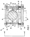
- a propellor attachment 10 comprises an upper plate 12 and a lower plate 14 which are connected by means of elongate bolts 16. These bolts 16 also serve to fix the propellor attachment 10 to a flange plate 18 of a drive shaft 20.
- a housing 22 comprises an upper member 24 and a lower member 26 which are connected by struts 28, said housing being slidable on bolts 16.
- Springs 30 are located on the bolts 16 between the lower member 26 of the housing and the lower plate 14.
- a rod 32 is fixed to the lower plate 14 and extends through the lower member 26 into the housing 22.
- a collar 34 is situated in the housing and this grips the centre of a propellor 36. The collar 34 has a flange 38 located adjacent the end of the rod 32.
- the propellor When a microlight aircraft takes off, the propellor must develop sufficient thrust to achieve take off. For a typical microlight aircraft the maximum thrust is approximately 320 LBS. However, when flying at a constant altitude the thrust developed by the propellor may be reduced to about 240 LBS.
- the springs 30 are designed so that they will only compress when a certain pre-determined force is applied thereon which is conveniently midway between the above two values, say 280 LBS. Consequently when the aircraft is in the process of taking off and the necessary thrust is developed by the propellor, the housing 22 will move towards the lower plate 14 in the direction of arrows A (since the propellor is situated at the rear of the aircraft) thereby compressing springs 30.
- a distinct advantage of the invention is that it allows the pitch of an aircraft propellor to be varied automatically thereby ensuring that the performance of the aircraft is optimum at all times, without requiring complicated and expensive hydraulic means.
Landscapes
- Engineering & Computer Science (AREA)
- Mechanical Engineering (AREA)
- Aviation & Aerospace Engineering (AREA)
- Structures Of Non-Positive Displacement Pumps (AREA)
- Emergency Lowering Means (AREA)
Applications Claiming Priority (2)
| Application Number | Priority Date | Filing Date | Title |
|---|---|---|---|
| GB878717437A GB8717437D0 (en) | 1987-07-23 | 1987-07-23 | Variable pitch propellor |
| GB8717437 | 1987-07-23 |
Publications (2)
| Publication Number | Publication Date |
|---|---|
| EP0300816A2 true EP0300816A2 (de) | 1989-01-25 |
| EP0300816A3 EP0300816A3 (de) | 1990-01-31 |
Family
ID=10621160
Family Applications (1)
| Application Number | Title | Priority Date | Filing Date |
|---|---|---|---|
| EP88306765A Withdrawn EP0300816A3 (de) | 1987-07-23 | 1988-07-22 | Luftschraube |
Country Status (3)
| Country | Link |
|---|---|
| EP (1) | EP0300816A3 (de) |
| AU (1) | AU1970688A (de) |
| GB (1) | GB8717437D0 (de) |
Family Cites Families (1)
| Publication number | Priority date | Publication date | Assignee | Title |
|---|---|---|---|---|
| DE2949433A1 (de) * | 1979-12-08 | 1981-06-11 | Anwander, Hermann, Ing.(grad.), 7928 Giengen | Verstelluftschraube fuer flugzeuge |
-
1987
- 1987-07-23 GB GB878717437A patent/GB8717437D0/en active Pending
-
1988
- 1988-07-22 EP EP88306765A patent/EP0300816A3/de not_active Withdrawn
- 1988-07-22 AU AU19706/88A patent/AU1970688A/en not_active Abandoned
Also Published As
| Publication number | Publication date |
|---|---|
| EP0300816A3 (de) | 1990-01-31 |
| GB8717437D0 (en) | 1987-08-26 |
| AU1970688A (en) | 1989-01-27 |
Similar Documents
| Publication | Publication Date | Title |
|---|---|---|
| US4613098A (en) | Devices which may be borne in air and on devices applicable therein | |
| US5615846A (en) | Extendable wing for guided missles and munitions | |
| US4695220A (en) | Actuator for variable vanes | |
| US4743163A (en) | Ram air turbine control system | |
| US7992820B2 (en) | Tandem powered tilt rotor aircraft | |
| EP0448672B1 (de) | Antriebssystem für schwenkbaren rotor | |
| US4678141A (en) | Aircraft launcher and retriever | |
| US5209429A (en) | Helicopter with retractable rotor for transport | |
| DE69332507T2 (de) | Rotorblattanordnung für unbemanntes Fluggerät | |
| US4842484A (en) | Blade gearing and pitch changing mechanisms for coaxial counterrotating propellers | |
| US2986877A (en) | Rotatable afterburners for jet aircraft | |
| GB2145777A (en) | Aircraft propeller system | |
| US2998080A (en) | Automatically adjustable propeller | |
| EP0811822B1 (de) | Ausfaltbares Flügelelement | |
| EP0341024A3 (de) | Geteilte Konfiguration für Flugzeug mit Turboproptriebwerk | |
| EP0300816A2 (de) | Luftschraube | |
| US4695014A (en) | Aircraft wing section movement apparatus | |
| US5149013A (en) | Retractable helicopter rotor | |
| US4890979A (en) | No-back apparatus for propeller pitch control | |
| IL101464A (en) | Support structure for main rotor assembly | |
| US4302154A (en) | Integrated transmission and rotor head | |
| GB1080209A (en) | Torsion joint or bearing | |
| US3469806A (en) | Drive mechanism operating against variable resistance | |
| US2862361A (en) | Fluid coupling | |
| US4245803A (en) | Two-dimensional inlet for a high speed winged flight vehicle |
Legal Events
| Date | Code | Title | Description |
|---|---|---|---|
| PUAI | Public reference made under article 153(3) epc to a published international application that has entered the european phase |
Free format text: ORIGINAL CODE: 0009012 |
|
| AK | Designated contracting states |
Kind code of ref document: A2 Designated state(s): AT BE CH DE ES FR GB GR IT LI LU NL SE |
|
| PUAL | Search report despatched |
Free format text: ORIGINAL CODE: 0009013 |
|
| AK | Designated contracting states |
Kind code of ref document: A3 Designated state(s): AT BE CH DE ES FR GB GR IT LI LU NL SE |
|
| STAA | Information on the status of an ep patent application or granted ep patent |
Free format text: STATUS: THE APPLICATION IS DEEMED TO BE WITHDRAWN |
|
| 18D | Application deemed to be withdrawn |
Effective date: 19900801 |