EP0300517B1 - Maschine zur Herstellung von Meandern in Widerstandsdraht - Google Patents
Maschine zur Herstellung von Meandern in Widerstandsdraht Download PDFInfo
- Publication number
- EP0300517B1 EP0300517B1 EP88200978A EP88200978A EP0300517B1 EP 0300517 B1 EP0300517 B1 EP 0300517B1 EP 88200978 A EP88200978 A EP 88200978A EP 88200978 A EP88200978 A EP 88200978A EP 0300517 B1 EP0300517 B1 EP 0300517B1
- Authority
- EP
- European Patent Office
- Prior art keywords
- wire
- machine
- shaping
- counter
- resistance wire
- Prior art date
- Legal status (The legal status is an assumption and is not a legal conclusion. Google has not performed a legal analysis and makes no representation as to the accuracy of the status listed.)
- Expired - Lifetime
Links
- 238000007493 shaping process Methods 0.000 title claims abstract description 9
- 230000015572 biosynthetic process Effects 0.000 claims description 7
- 238000002347 injection Methods 0.000 claims description 5
- 239000007924 injection Substances 0.000 claims description 5
- 230000002093 peripheral effect Effects 0.000 claims description 5
- 238000005452 bending Methods 0.000 abstract description 8
- 238000010276 construction Methods 0.000 description 2
- 238000000034 method Methods 0.000 description 2
- 239000007795 chemical reaction product Substances 0.000 description 1
- 238000010586 diagram Methods 0.000 description 1
- 230000005611 electricity Effects 0.000 description 1
- 239000012467 final product Substances 0.000 description 1
- 239000000047 product Substances 0.000 description 1
Images
Classifications
-
- B—PERFORMING OPERATIONS; TRANSPORTING
- B21—MECHANICAL METAL-WORKING WITHOUT ESSENTIALLY REMOVING MATERIAL; PUNCHING METAL
- B21F—WORKING OR PROCESSING OF METAL WIRE
- B21F1/00—Bending wire other than coiling; Straightening wire
- B21F1/04—Undulating
-
- H—ELECTRICITY
- H01—ELECTRIC ELEMENTS
- H01C—RESISTORS
- H01C17/00—Apparatus or processes specially adapted for manufacturing resistors
- H01C17/04—Apparatus or processes specially adapted for manufacturing resistors adapted for winding the resistive element
Definitions
- the invention relates to a machine for shaping resistance wire which permits a high quality product to be obtained and is based on an original shaping principle which is highly innovative compared to techniques in current use and eliminates the relative disadvantages.
- the machines which are currently used to shape resistance wire into undulations for the construction of electrical resistances for electrical household appliances generally employ a shaping system constituted by gears or disks into which wedges have been inserted. When they rotate, these gears or disks with inserted wedges drag and pull the resistance wire and shape it in accordance with the parameters of the resistance to be constructed.
- the action of pulling the resistance wire causes stretching and also buckling of the wire, creating considerable disadvantages during the construction stage because of cracks in the wire and during utilisation in an electrical household appliance because of the production of hot spots and a consequent interruption in the flow of electricity in said appliance.
- the machine according to the present invention eliminates the disadvantages of the technique currently used, since it is based on the original principle of injecting the resistance wire instead of pulling it and thus does not use gears or disks with wedges for shaping
- the technical problem is solved by the invention, in which the wire is pushed and not pulled, feeding it in at a speed higher than the speed at which it exits from the machine, so that the wire is forced to bend at a precise point, determined by the parameters which can be changed as requested, and defined by the conformation of the elements which guide the wire inside the machine, and thus the wire does not come into contact with any mechanical part which can damage it at the point at which it undergoes bending.
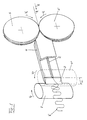
- the machine basically consists of an injection system constituted by two counter-rotating disks S and S' of a suitable shape, which form the thrust wheels for the resistance wire R coming from an appropriate feeding system which is not shown in the drawings; a wire guide G provided with a channel C for the injection of the wire R into a formation zone Z at the terminal part of the guide which is shaped to form a chamber of free outlet zone in which the bending of the wire R takes place.
- This zone has a dimension D equal to the distance between the exit of channel C of wire guide G and a point of tangency with the braking system, constituted by two braking rollers or cylinders F and F' which are also counter-rotating at a peripheral speed which is appropriately lower than that of the direction of rotation of counter-rotating thrust disks S and S'.
- forces D r are induced on the wire R in such a way as to oblige the wire to bend at a precise point.
- the wire is pushed by two thrust wheels S and S' into an obligatory path, in other words channel C of guide G and carried in proximity to the braking wheels F and F' which are also rotating and constitute a partial obstacle because their peripheral speed is lower than that of the thrust wheels S and S'.
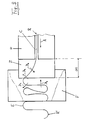
- This obstacle can be fixed or mobile according to the shaping requirements of the wire.
- This obstacle impedes the linear passage of the wire R, which is thus forced to discharge its surplus from the opposite formation zone Z of the guide, situated between the guide and the braking rollers F and F'.
- the wire R will acquire the special undulating shape, which is produced by the combined forces of the speed and the bending resistance of the wire which come into play at all the points involved in the formation zone, as well as the walls of the guide.
- V r relative speed V s - V f
- V s the peripheral speed of the thrust wheels
- V f the peripheral speed of the braking wheels
- E the spring-back due to the elasticity of the wire
- V r -E determines the quantity of the final product of undulated wire R' in m ⁇ 1
Landscapes
- Engineering & Computer Science (AREA)
- Manufacturing & Machinery (AREA)
- Microelectronics & Electronic Packaging (AREA)
- Mechanical Engineering (AREA)
- Electrical Discharge Machining, Electrochemical Machining, And Combined Machining (AREA)
- Wire Processing (AREA)
- Superconductors And Manufacturing Methods Therefor (AREA)
- Golf Clubs (AREA)
- Ropes Or Cables (AREA)
- Apparatuses And Processes For Manufacturing Resistors (AREA)
Claims (1)
- Maschine zum Formen von Widerstandsdraht in eine wellenförmige Mäanderform zum Herstellen von elektrischen Widerständen, wobei die Maschine versehen ist mit: einem Drahteinspeissystem, welches sich aus zwei in entgegengesetzter Richtung rotierenden Scheiben (S,S') zusammensetzt, welche eine axiale Schubkraft auf den Draht übertragen; einer Drahtführung (G) mit einem Kanal (C) zum Einspeisen von Draht in eine Formgebungszone (Z), wobei die Formgebungszone durch eine freie Auslaßzone der Drahtführung ausgebildet ist; einem Bremssystem, weiches sich aus zwei in entgegengesetzte Richtung rotierenden Walzen (F,F') zusammensetzt, welche mit einer geringeren Umfangsgeschwindigkeit als derjenigen der in entgegengesetzter Richtung rotierenden Scheiben des Drahteinspeissystems rotieren; und wobei der Draht in der Formgebungszone (Z) geformt wird, in welcher überschüssiger Draht durch die Differenz der Geschwindigkeit des Einspeissystems und des Bremssystems geschaffen wird, und der Draht infolgedessen dazu gezwungen wird, sich selbst zu biegen und so die Form von wellenförmigen Mäandern einzunehmen.
Priority Applications (1)
| Application Number | Priority Date | Filing Date | Title |
|---|---|---|---|
| AT88200978T ATE87121T1 (de) | 1987-05-21 | 1988-05-17 | Maschine zur herstellung von meandern in widerstandsdraht. |
Applications Claiming Priority (2)
| Application Number | Priority Date | Filing Date | Title |
|---|---|---|---|
| IT2062087 | 1987-05-21 | ||
| IT20620/87A IT1205666B (it) | 1987-05-21 | 1987-05-21 | Macchina per la sagomatura ad onda,col principio dell'iniezione,di filo resistivo per l'esecuzione di resistenza elettriche ed altri prodotti |
Publications (3)
| Publication Number | Publication Date |
|---|---|
| EP0300517A2 EP0300517A2 (de) | 1989-01-25 |
| EP0300517A3 EP0300517A3 (en) | 1990-02-14 |
| EP0300517B1 true EP0300517B1 (de) | 1993-03-17 |
Family
ID=11169660
Family Applications (1)
| Application Number | Title | Priority Date | Filing Date |
|---|---|---|---|
| EP88200978A Expired - Lifetime EP0300517B1 (de) | 1987-05-21 | 1988-05-17 | Maschine zur Herstellung von Meandern in Widerstandsdraht |
Country Status (5)
| Country | Link |
|---|---|
| EP (1) | EP0300517B1 (de) |
| AT (1) | ATE87121T1 (de) |
| DE (1) | DE3879306T2 (de) |
| ES (1) | ES2040322T3 (de) |
| IT (1) | IT1205666B (de) |
Families Citing this family (1)
| Publication number | Priority date | Publication date | Assignee | Title |
|---|---|---|---|---|
| JP5319219B2 (ja) * | 2008-09-16 | 2013-10-16 | 株式会社ブリヂストン | コード製造装置及びコード製造方法 |
Family Cites Families (1)
| Publication number | Priority date | Publication date | Assignee | Title |
|---|---|---|---|---|
| US4072921A (en) * | 1976-04-27 | 1978-02-07 | Amf Incorporated | Low inductance precision resistor deposited on an adhesive backing and wound on a bobbin |
-
1987
- 1987-05-21 IT IT20620/87A patent/IT1205666B/it active
-
1988
- 1988-05-17 EP EP88200978A patent/EP0300517B1/de not_active Expired - Lifetime
- 1988-05-17 ES ES198888200978T patent/ES2040322T3/es not_active Expired - Lifetime
- 1988-05-17 DE DE8888200978T patent/DE3879306T2/de not_active Expired - Lifetime
- 1988-05-17 AT AT88200978T patent/ATE87121T1/de not_active IP Right Cessation
Also Published As
| Publication number | Publication date |
|---|---|
| IT8720620A0 (it) | 1987-05-21 |
| DE3879306D1 (de) | 1993-04-22 |
| ATE87121T1 (de) | 1993-04-15 |
| EP0300517A3 (en) | 1990-02-14 |
| IT1205666B (it) | 1989-03-31 |
| ES2040322T3 (es) | 1993-10-16 |
| DE3879306T2 (de) | 1993-07-22 |
| EP0300517A2 (de) | 1989-01-25 |
Similar Documents
| Publication | Publication Date | Title |
|---|---|---|
| GB1601838A (en) | Manufacturing cable elements comprising optical fibres | |
| US4528148A (en) | Method and apparatus for forming grooves in an optical fiber support | |
| GB533032A (en) | Improvements relating to the production of crimped glass fibres | |
| ES462147A1 (es) | Perfeccionamientos introducidos en un cordoncillo de alambrede acero. | |
| EP0300517B1 (de) | Maschine zur Herstellung von Meandern in Widerstandsdraht | |
| US3357222A (en) | Method of forming a spiral of resilient materials, a machine and a machine installation for the same | |
| US3413792A (en) | Process and apparatus for the manufacture of concentric conductors for electric cables | |
| US4195469A (en) | Method and device for producing metallic cords | |
| AU1759788A (en) | Manufacture of an elongate flexible core for an optical cable | |
| US1030426A (en) | Process of manufacturing cables. | |
| US1497809A (en) | Process of corrugating pulpboard | |
| GB2016363A (en) | An improved bundle of fibrous elements, method and apparatus for producing thereof | |
| CA1099877A (en) | Production of cables with undulated tension relief elements | |
| GB2382355A (en) | Card clothing | |
| SU859512A1 (ru) | Способ изготовлени витых проволочных изделий с переменным направлением свивки | |
| US3451204A (en) | Process and apparatus for making paper covered electrical cable conductors | |
| EP0637766B1 (de) | Verfahren zur Herstellung eines optischen Kabels | |
| SU889198A2 (ru) | Устройство дл изготовлени спиралей шнеков | |
| CA2392426A1 (en) | Double twist twisting machine | |
| SU699062A1 (ru) | Деформатор к канатовьющей машине | |
| JPS57113752A (en) | Manufacture of commutator | |
| SU1124386A1 (ru) | Способ изготовлени кабел с профилированным сердечником | |
| JPS6411361B2 (de) | ||
| Joo | AN INVESTIGATION OF THE PERFORMANCE OF A CORE-TYPE FRICTION SPINNING MACHINE AND THE PRODUCTS MADE THEREFROM (AIR-JET) | |
| JP2546376B2 (ja) | 丸形ケーブルの製造方法 |
Legal Events
| Date | Code | Title | Description |
|---|---|---|---|
| PUAI | Public reference made under article 153(3) epc to a published international application that has entered the european phase |
Free format text: ORIGINAL CODE: 0009012 |
|
| AK | Designated contracting states |
Kind code of ref document: A2 Designated state(s): AT BE CH DE ES FR GB GR IT LI LU NL SE |
|
| PUAL | Search report despatched |
Free format text: ORIGINAL CODE: 0009013 |
|
| AK | Designated contracting states |
Kind code of ref document: A3 Designated state(s): AT BE CH DE ES FR GB GR IT LI LU NL SE |
|
| 17P | Request for examination filed |
Effective date: 19900614 |
|
| 17Q | First examination report despatched |
Effective date: 19910826 |
|
| GRAA | (expected) grant |
Free format text: ORIGINAL CODE: 0009210 |
|
| AK | Designated contracting states |
Kind code of ref document: B1 Designated state(s): AT BE CH DE ES FR GB GR IT LI LU NL SE |
|
| PG25 | Lapsed in a contracting state [announced via postgrant information from national office to epo] |
Ref country code: GR Free format text: LAPSE BECAUSE OF FAILURE TO SUBMIT A TRANSLATION OF THE DESCRIPTION OR TO PAY THE FEE WITHIN THE PRESCRIBED TIME-LIMIT Effective date: 19930317 |
|
| REF | Corresponds to: |
Ref document number: 87121 Country of ref document: AT Date of ref document: 19930415 Kind code of ref document: T |
|
| REF | Corresponds to: |
Ref document number: 3879306 Country of ref document: DE Date of ref document: 19930422 |
|
| PGFP | Annual fee paid to national office [announced via postgrant information from national office to epo] |
Ref country code: LU Payment date: 19930429 Year of fee payment: 6 |
|
| PGFP | Annual fee paid to national office [announced via postgrant information from national office to epo] |
Ref country code: AT Payment date: 19930506 Year of fee payment: 6 |
|
| PGFP | Annual fee paid to national office [announced via postgrant information from national office to epo] |
Ref country code: ES Payment date: 19930517 Year of fee payment: 6 |
|
| PGFP | Annual fee paid to national office [announced via postgrant information from national office to epo] |
Ref country code: SE Payment date: 19930525 Year of fee payment: 6 |
|
| PGFP | Annual fee paid to national office [announced via postgrant information from national office to epo] |
Ref country code: NL Payment date: 19930531 Year of fee payment: 6 |
|
| PGFP | Annual fee paid to national office [announced via postgrant information from national office to epo] |
Ref country code: BE Payment date: 19930603 Year of fee payment: 6 |
|
| ITF | It: translation for a ep patent filed | ||
| ET | Fr: translation filed | ||
| EPTA | Lu: last paid annual fee | ||
| REG | Reference to a national code |
Ref country code: ES Ref legal event code: FG2A Ref document number: 2040322 Country of ref document: ES Kind code of ref document: T3 |
|
| PLBE | No opposition filed within time limit |
Free format text: ORIGINAL CODE: 0009261 |
|
| STAA | Information on the status of an ep patent application or granted ep patent |
Free format text: STATUS: NO OPPOSITION FILED WITHIN TIME LIMIT |
|
| 26N | No opposition filed | ||
| PG25 | Lapsed in a contracting state [announced via postgrant information from national office to epo] |
Ref country code: LU Free format text: LAPSE BECAUSE OF NON-PAYMENT OF DUE FEES Effective date: 19940517 Ref country code: AT Effective date: 19940517 |
|
| PG25 | Lapsed in a contracting state [announced via postgrant information from national office to epo] |
Ref country code: SE Effective date: 19940518 Ref country code: ES Free format text: LAPSE BECAUSE OF NON-PAYMENT OF DUE FEES Effective date: 19940518 |
|
| PG25 | Lapsed in a contracting state [announced via postgrant information from national office to epo] |
Ref country code: BE Effective date: 19940531 |
|
| BERE | Be: lapsed |
Owner name: AGA S.R.L. Effective date: 19940531 |
|
| PG25 | Lapsed in a contracting state [announced via postgrant information from national office to epo] |
Ref country code: NL Effective date: 19941201 |
|
| NLV4 | Nl: lapsed or anulled due to non-payment of the annual fee | ||
| EUG | Se: european patent has lapsed |
Ref document number: 88200978.0 Effective date: 19941210 |
|
| EUG | Se: european patent has lapsed |
Ref document number: 88200978.0 |
|
| REG | Reference to a national code |
Ref country code: CH Ref legal event code: PUE Owner name: A.G.A. S.R.L. TRANSFER- GAMMA S.P.A. |
|
| REG | Reference to a national code |
Ref country code: ES Ref legal event code: FD2A Effective date: 19990201 |
|
| REG | Reference to a national code |
Ref country code: GB Ref legal event code: 732E |
|
| REG | Reference to a national code |
Ref country code: FR Ref legal event code: TP |
|
| REG | Reference to a national code |
Ref country code: GB Ref legal event code: IF02 |
|
| PGFP | Annual fee paid to national office [announced via postgrant information from national office to epo] |
Ref country code: DE Payment date: 20070529 Year of fee payment: 20 |
|
| PGFP | Annual fee paid to national office [announced via postgrant information from national office to epo] |
Ref country code: CH Payment date: 20070724 Year of fee payment: 20 Ref country code: GB Payment date: 20070509 Year of fee payment: 20 |
|
| PGFP | Annual fee paid to national office [announced via postgrant information from national office to epo] |
Ref country code: IT Payment date: 20070524 Year of fee payment: 20 |
|
| PGFP | Annual fee paid to national office [announced via postgrant information from national office to epo] |
Ref country code: FR Payment date: 20070524 Year of fee payment: 20 |
|
| REG | Reference to a national code |
Ref country code: GB Ref legal event code: PE20 Expiry date: 20080516 |
|
| REG | Reference to a national code |
Ref country code: CH Ref legal event code: PL |
|
| PG25 | Lapsed in a contracting state [announced via postgrant information from national office to epo] |
Ref country code: GB Free format text: LAPSE BECAUSE OF EXPIRATION OF PROTECTION Effective date: 20080516 |