EP0300116B1 - Support for print-outs - Google Patents
Support for print-outs Download PDFInfo
- Publication number
- EP0300116B1 EP0300116B1 EP88101803A EP88101803A EP0300116B1 EP 0300116 B1 EP0300116 B1 EP 0300116B1 EP 88101803 A EP88101803 A EP 88101803A EP 88101803 A EP88101803 A EP 88101803A EP 0300116 B1 EP0300116 B1 EP 0300116B1
- Authority
- EP
- European Patent Office
- Prior art keywords
- support
- outs
- central body
- inner portion
- Prior art date
- Legal status (The legal status is an assumption and is not a legal conclusion. Google has not performed a legal analysis and makes no representation as to the accuracy of the status listed.)
- Expired - Lifetime
Links
- 230000001419 dependent effect Effects 0.000 description 1
Images

Classifications
-
- B—PERFORMING OPERATIONS; TRANSPORTING
- B42—BOOKBINDING; ALBUMS; FILES; SPECIAL PRINTED MATTER
- B42F—SHEETS TEMPORARILY ATTACHED TOGETHER; FILING APPLIANCES; FILE CARDS; INDEXING
- B42F15/00—Suspended filing appliances
- B42F15/0011—Suspended filing appliances for sheets, stacks of temporarily bound sheets
- B42F15/0052—Suspended filing appliances for sheets, stacks of temporarily bound sheets for suspending stacks of temporarily bound sheets
- B42F15/0058—Suspended filing appliances for sheets, stacks of temporarily bound sheets for suspending stacks of temporarily bound sheets with fixed suspension means
Definitions
- This invention concerns a support for print-outs.
- the invention concerns a support which can be hung and/or carried and which is suitable to uphold, position and secure print-outs arranged vertically.
- the support according to the invention is able to be hung on monorail supports or on support points spaced apart and to bear print-outs below itself.
- Document GB-A-2 018 202 discloses a document holder comprising two side sections connected together by a hinge section so that said side sections can be swung toward and away from one another, at least two mounting pins secured to one of said side sections, and manually releasable locking means for locking said sections together so as to hold captive said documents on said pins between said sections.
- Document DE-A-1 761 772 discloses a document holder constituted by an angled supporting rail comprising pins for holding documents and an angled pressure rail having clamping sockets located in positions corresponding to said pins.
- a support for print-outs consists of a body and of two side panels positioned diametrically opposite to each other in relation to the body and along the length of the body.
- Each of the side panels consists of an inner portion and an outer portion, both of which can be folded lengthwise as required.
- the body comprises terminal attachments and a central attachment and also a handle to carry the support and a window for the application of information regarding the contents of the print-outs.
- the body includes also at least one terminal limiting means able to position the print-outs lengthwise within the support.
- the outer portions of the side panels comprise holes that cooperate with guides within which there can run sliders that are suitable to secure clamping means, which may be means comprising a cord or pin.
- the invention is therefor embodied with a support for print-outs according to the contents of Claim 1 and the dependent claims.
- a support 10 for print-outs comprises a body 11 equipped in a specific manner.
- the body 11 includes at its ends terminal attachments 13 and at its centre a central attachment 12.
- terminal attachments 13 serve for the support to be upheld on support points spaced apart, whereas the central attachment 12 serves for the support to be upheld on substantially T-shaped central rail attachments.
- a handle 14 is included in an intermediate position for the carrying of the support, while a window 15 is provided for the application of information regarding the contents of the print-outs hanging from the support.
- Two side panels 17, each of them consisting of an inner portion 18 and a outer portion 118, are comprised on the two lengthwise sides of the body 11.
- the portions can be folded along preferred lines in relation to the body and to each other along their length.
- the outer portions 118 include a coordinated plurality of holes 19 suitably spaced apart, which cooperate with guides 20.
- the outer portions 118 alone (Fig.5) or the inner portions 18 too (Fig.4) may be folded, depending on the quantity of the print-outs to be held.
- the reciprocal connection of the portions 18-118 of the side panels can be provided by a cord 21 (Fig.4) or by pins 23 (Fig.5).
- Sliders 22 for cord or sliders 24 for pins can cooperate in guides 20, depending on the type of connection and support to be provided.
Landscapes
- Displays For Variable Information Using Movable Means (AREA)
- Adhesives Or Adhesive Processes (AREA)
- Sheet Holders (AREA)
- Mirrors, Picture Frames, Photograph Stands, And Related Fastening Devices (AREA)
- Filters For Electric Vacuum Cleaners (AREA)
- Slide Fasteners, Snap Fasteners, And Hook Fasteners (AREA)
- Photoreceptors In Electrophotography (AREA)
- Vending Machines For Individual Products (AREA)
- Mechanical Pencils And Projecting And Retracting Systems Therefor, And Multi-System Writing Instruments (AREA)
Abstract
Description
- This invention concerns a support for print-outs. To be more exact, the invention concerns a support which can be hung and/or carried and which is suitable to uphold, position and secure print-outs arranged vertically.
- The support according to the invention is able to be hung on monorail supports or on support points spaced apart and to bear print-outs below itself.
- Supports for print-outs of the type in question are known but entail many drawbacks as regards their application and use.
- Document GB-A-2 018 202 discloses a document holder comprising two side sections connected together by a hinge section so that said side sections can be swung toward and away from one another, at least two mounting pins secured to one of said side sections, and manually releasable locking means for locking said sections together so as to hold captive said documents on said pins between said sections.
- Document DE-A-1 761 772 discloses a document holder constituted by an angled supporting rail comprising pins for holding documents and an angled pressure rail having clamping sockets located in positions corresponding to said pins.
- The present applicant has designed, tested and embodied this invention so as to obviate such drawbacks.
- According to the invention a support for print-outs consists of a body and of two side panels positioned diametrically opposite to each other in relation to the body and along the length of the body.
- Each of the side panels consists of an inner portion and an outer portion, both of which can be folded lengthwise as required.
- The body comprises terminal attachments and a central attachment and also a handle to carry the support and a window for the application of information regarding the contents of the print-outs.
- According to the invention the body includes also at least one terminal limiting means able to position the print-outs lengthwise within the support.
- The outer portions of the side panels comprise holes that cooperate with guides within which there can run sliders that are suitable to secure clamping means, which may be means comprising a cord or pin.
- The invention is therefor embodied with a support for print-outs according to the contents of Claim 1 and the dependent claims.
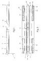
- Let us now see a preferred embodiment of the invention with the help of the attached figures, which are given as a non-restrictive example and show the following:-
- Fig.1
- shows a side view of a support according to the invention;
- Fig.2
- gives a plan view of a support according to Fig.1;
- Fig.3
- shows a cross section of the embodiment of Fig.1;
- Figs.4
- and 5 show two conditions of use of the embodiment of Fig.1.
- According to the invention a
support 10 for print-outs comprises abody 11 equipped in a specific manner. Thebody 11 includes at itsends terminal attachments 13 and at its centre acentral attachment 12. - The
terminal attachments 13 serve for the support to be upheld on support points spaced apart, whereas thecentral attachment 12 serves for the support to be upheld on substantially T-shaped central rail attachments. - A
handle 14 is included in an intermediate position for the carrying of the support, while awindow 15 is provided for the application of information regarding the contents of the print-outs hanging from the support. - Two
side panels 17, each of them consisting of aninner portion 18 and aouter portion 118, are comprised on the two lengthwise sides of thebody 11. The portions can be folded along preferred lines in relation to the body and to each other along their length. - The
outer portions 118 include a coordinated plurality ofholes 19 suitably spaced apart, which cooperate withguides 20. - The
outer portions 118 alone (Fig.5) or theinner portions 18 too (Fig.4) may be folded, depending on the quantity of the print-outs to be held. - The reciprocal connection of the portions 18-118 of the side panels can be provided by a cord 21 (Fig.4) or by pins 23 (Fig.5).
-
Sliders 22 for cord orsliders 24 for pins can cooperate inguides 20, depending on the type of connection and support to be provided.
Claims (5)
- A support for print-outs which is suitable to bear print-outs along the axis of the support itself (10) comprising a generally rectangular body having terminal ends, sides and a center and further having support attachments (12,13) located longitudinally at said terminal ends and center for facilitating hanging the support, side panels (17) located symmetrically at the sides and along the length of the central body (11), characterized in that each of the side panels (17) includes an inner portion (18) adjacent the central body and an outer portion (118) adjacent the inner portion and spaced from the central body, the inner portion being pivotally connected to the central body for pivotal movement thereabout, and the outer portion being pivotally connected to the inner portion for pivotal movement thereabout, and in that it further comprises a handle (14) on said central body for carrying the support.
- Support according to claim 1, characterized in that the central body (11) comprises at least one terminal limiting means (16) for positioning print-outs longitudinally within the support.
- Support as claimed in Claim 1 or 2, in which the central body (11) comprises at least one window (15) to display information.
- Support as claimed in any claim hereinbefore, in which a plurality of holes (19) for the passage of means (21-23) to clamp and bear print-outs is comprised in and along the outer portion (118).
- Support as claimed in any claim hereinbefore, in which guide means (20) suitable to clamp sliders (22-24) for the fixture of anchorage means (21-23) are comprised in cooperation with the holes (19).
Priority Applications (1)
| Application Number | Priority Date | Filing Date | Title |
|---|---|---|---|
| AT88101803T ATE77990T1 (en) | 1987-07-21 | 1988-02-08 | HANGING DEVICE FOR DOCUMENTS. |
Applications Claiming Priority (2)
| Application Number | Priority Date | Filing Date | Title |
|---|---|---|---|
| IT8760411U IT218569Z2 (en) | 1987-07-21 | 1987-07-21 | TABULATE HOLDER SUPPORT. |
| IT6041187U | 1987-07-21 |
Publications (3)
| Publication Number | Publication Date |
|---|---|
| EP0300116A2 EP0300116A2 (en) | 1989-01-25 |
| EP0300116A3 EP0300116A3 (en) | 1989-05-03 |
| EP0300116B1 true EP0300116B1 (en) | 1992-07-08 |
Family
ID=11290852
Family Applications (1)
| Application Number | Title | Priority Date | Filing Date |
|---|---|---|---|
| EP88101803A Expired - Lifetime EP0300116B1 (en) | 1987-07-21 | 1988-02-08 | Support for print-outs |
Country Status (5)
| Country | Link |
|---|---|
| US (1) | US4893714A (en) |
| EP (1) | EP0300116B1 (en) |
| AT (1) | ATE77990T1 (en) |
| DE (1) | DE3872615T2 (en) |
| IT (1) | IT218569Z2 (en) |
Family Cites Families (7)
| Publication number | Priority date | Publication date | Assignee | Title |
|---|---|---|---|---|
| BE516287A (en) * | ||||
| US2969793A (en) * | 1954-06-18 | 1961-01-31 | Rud Furrer Sohne A G | Suspension file element with indicia carrier |
| DE1761772A1 (en) * | 1968-07-05 | 1971-08-12 | Fischer Franz Josef | Hanging folder for the storage of especially endless lists |
| US3790242A (en) * | 1972-01-24 | 1974-02-05 | Mead Corp | Binder carrier and support structure |
| US3865445A (en) * | 1973-02-26 | 1975-02-11 | Wright Barry Corp | Hanging binder |
| US4009784A (en) * | 1974-10-15 | 1977-03-01 | Elias Abram G | Document hanging apparatus |
| US4171854A (en) * | 1978-04-10 | 1979-10-23 | Wright Line Inc. | Document holder |
-
1987
- 1987-07-21 IT IT8760411U patent/IT218569Z2/en active
-
1988
- 1988-02-08 EP EP88101803A patent/EP0300116B1/en not_active Expired - Lifetime
- 1988-02-08 DE DE8888101803T patent/DE3872615T2/en not_active Expired - Lifetime
- 1988-02-08 AT AT88101803T patent/ATE77990T1/en active
- 1988-02-19 US US07/158,220 patent/US4893714A/en not_active Expired - Fee Related
Also Published As
| Publication number | Publication date |
|---|---|
| EP0300116A3 (en) | 1989-05-03 |
| DE3872615D1 (en) | 1992-08-13 |
| DE3872615T2 (en) | 1992-12-17 |
| IT218569Z2 (en) | 1992-06-17 |
| US4893714A (en) | 1990-01-16 |
| ATE77990T1 (en) | 1992-07-15 |
| EP0300116A2 (en) | 1989-01-25 |
Similar Documents
| Publication | Publication Date | Title |
|---|---|---|
| KR880012799A (en) | Conveyer | |
| US4708309A (en) | Supporting device having infinitely adjustable jibs | |
| DE50011196D1 (en) | Bearing arrangement for supporting tensile forces and bearing head for the bearing assembly | |
| ATE48298T1 (en) | SUPPORT RAIL FOR SUSPENDED CEILINGS AND ACCESSORIES. | |
| KR890701456A (en) | Plate handling frame | |
| HUP0000630A2 (en) | A universal mounting and parallel guidance arrangement for a window screening device | |
| SE8505890D0 (en) | cargo hook | |
| CA2004228A1 (en) | Multiple-garment hanger | |
| DE69405863D1 (en) | SUPPORT OR SPLINKING DEVICE FOR A RAILWAY RAIL | |
| EP0300116A2 (en) | Support for print-outs | |
| DE68912737D1 (en) | Holding rail for sample book. | |
| CA1305693C (en) | Support for print-outs | |
| US2463047A (en) | Ceiling | |
| FR2726592B1 (en) | CARRIER STRUCTURE FOR REMOVABLE AND SUSPENDED CEILING IMPLEMENTED IN SUCH A CARRIER STRUCTURE | |
| US4156514A (en) | Cylinder support assembly | |
| DE59304162D1 (en) | Hanging rail for hanging bags or folders | |
| JPH0649049Y2 (en) | Caterpillar | |
| JP2000289971A (en) | Lifting equipment for heavy objects | |
| CS267711B1 (en) | Hanger for suspension track | |
| DE69934118D1 (en) | TELESCOPIC GUIDE FOR CABINETS AND HOLDERS FOR THIS | |
| US3254437A (en) | Mail box fixture | |
| SU1257022A1 (en) | Device for carrying loads | |
| DE1047402B (en) | Power cable routing for the movable trolleys of overhead traveling cranes | |
| DE69501814D1 (en) | Apparatus for balancing the forces acting on an arm pulled under a load | |
| RU25470U1 (en) | DEVICE FOR SUSPENSION OF CONTACT WIRING OF RAILWAY TRANSPORT |
Legal Events
| Date | Code | Title | Description |
|---|---|---|---|
| PUAI | Public reference made under article 153(3) epc to a published international application that has entered the european phase |
Free format text: ORIGINAL CODE: 0009012 |
|
| AK | Designated contracting states |
Kind code of ref document: A2 Designated state(s): AT BE CH DE ES FR GB GR LI LU NL SE |
|
| PUAL | Search report despatched |
Free format text: ORIGINAL CODE: 0009013 |
|
| AK | Designated contracting states |
Kind code of ref document: A3 Designated state(s): AT BE CH DE ES FR GB GR LI LU NL SE |
|
| 17P | Request for examination filed |
Effective date: 19890724 |
|
| 17Q | First examination report despatched |
Effective date: 19901031 |
|
| GRAA | (expected) grant |
Free format text: ORIGINAL CODE: 0009210 |
|
| AK | Designated contracting states |
Kind code of ref document: B1 Designated state(s): AT BE CH DE ES FR GB GR LI LU NL SE |
|
| PG25 | Lapsed in a contracting state [announced via postgrant information from national office to epo] |
Ref country code: SE Effective date: 19920708 Ref country code: NL Effective date: 19920708 Ref country code: LI Effective date: 19920708 Ref country code: GR Free format text: LAPSE BECAUSE OF FAILURE TO SUBMIT A TRANSLATION OF THE DESCRIPTION OR TO PAY THE FEE WITHIN THE PRESCRIBED TIME-LIMIT Effective date: 19920708 Ref country code: ES Free format text: THE PATENT HAS BEEN ANNULLED BY A DECISION OF A NATIONAL AUTHORITY Effective date: 19920708 Ref country code: CH Effective date: 19920708 Ref country code: BE Effective date: 19920708 Ref country code: AT Effective date: 19920708 |
|
| REF | Corresponds to: |
Ref document number: 77990 Country of ref document: AT Date of ref document: 19920715 Kind code of ref document: T |
|
| REF | Corresponds to: |
Ref document number: 3872615 Country of ref document: DE Date of ref document: 19920813 |
|
| ET | Fr: translation filed | ||
| REG | Reference to a national code |
Ref country code: CH Ref legal event code: PL |
|
| NLV1 | Nl: lapsed or annulled due to failure to fulfill the requirements of art. 29p and 29m of the patents act | ||
| PG25 | Lapsed in a contracting state [announced via postgrant information from national office to epo] |
Ref country code: GB Effective date: 19930208 |
|
| PG25 | Lapsed in a contracting state [announced via postgrant information from national office to epo] |
Ref country code: LU Free format text: LAPSE BECAUSE OF NON-PAYMENT OF DUE FEES Effective date: 19930228 |
|
| PLBE | No opposition filed within time limit |
Free format text: ORIGINAL CODE: 0009261 |
|
| STAA | Information on the status of an ep patent application or granted ep patent |
Free format text: STATUS: NO OPPOSITION FILED WITHIN TIME LIMIT |
|
| 26N | No opposition filed | ||
| GBPC | Gb: european patent ceased through non-payment of renewal fee |
Effective date: 19930208 |
|
| PG25 | Lapsed in a contracting state [announced via postgrant information from national office to epo] |
Ref country code: FR Effective date: 19931029 |
|
| PG25 | Lapsed in a contracting state [announced via postgrant information from national office to epo] |
Ref country code: DE Effective date: 19931103 |
|
| REG | Reference to a national code |
Ref country code: FR Ref legal event code: ST |