EP0300012B1 - Improved total heart prosthesis - Google Patents
Improved total heart prosthesis Download PDFInfo
- Publication number
- EP0300012B1 EP0300012B1 EP88901281A EP88901281A EP0300012B1 EP 0300012 B1 EP0300012 B1 EP 0300012B1 EP 88901281 A EP88901281 A EP 88901281A EP 88901281 A EP88901281 A EP 88901281A EP 0300012 B1 EP0300012 B1 EP 0300012B1
- Authority
- EP
- European Patent Office
- Prior art keywords
- prosthesis
- membrane
- bellows
- elongation
- total heart
- Prior art date
- Legal status (The legal status is an assumption and is not a legal conclusion. Google has not performed a legal analysis and makes no representation as to the accuracy of the status listed.)
- Expired - Lifetime
Links
Images

Classifications
-
- F—MECHANICAL ENGINEERING; LIGHTING; HEATING; WEAPONS; BLASTING
- F04—POSITIVE - DISPLACEMENT MACHINES FOR LIQUIDS; PUMPS FOR LIQUIDS OR ELASTIC FLUIDS
- F04B—POSITIVE-DISPLACEMENT MACHINES FOR LIQUIDS; PUMPS
- F04B43/00—Machines, pumps, or pumping installations having flexible working members
- F04B43/02—Machines, pumps, or pumping installations having flexible working members having plate-like flexible members, e.g. diaphragms
- F04B43/06—Pumps having fluid drive
-
- A—HUMAN NECESSITIES
- A61—MEDICAL OR VETERINARY SCIENCE; HYGIENE
- A61M—DEVICES FOR INTRODUCING MEDIA INTO, OR ONTO, THE BODY; DEVICES FOR TRANSDUCING BODY MEDIA OR FOR TAKING MEDIA FROM THE BODY; DEVICES FOR PRODUCING OR ENDING SLEEP OR STUPOR
- A61M60/00—Blood pumps; Devices for mechanical circulatory actuation; Balloon pumps for circulatory assistance
- A61M60/10—Location thereof with respect to the patient's body
- A61M60/122—Implantable pumps or pumping devices, i.e. the blood being pumped inside the patient's body
- A61M60/196—Implantable pumps or pumping devices, i.e. the blood being pumped inside the patient's body replacing the entire heart, e.g. total artificial hearts [TAH]
-
- A—HUMAN NECESSITIES
- A61—MEDICAL OR VETERINARY SCIENCE; HYGIENE
- A61M—DEVICES FOR INTRODUCING MEDIA INTO, OR ONTO, THE BODY; DEVICES FOR TRANSDUCING BODY MEDIA OR FOR TAKING MEDIA FROM THE BODY; DEVICES FOR PRODUCING OR ENDING SLEEP OR STUPOR
- A61M60/00—Blood pumps; Devices for mechanical circulatory actuation; Balloon pumps for circulatory assistance
- A61M60/40—Details relating to driving
- A61M60/424—Details relating to driving for positive displacement blood pumps
- A61M60/427—Details relating to driving for positive displacement blood pumps the force acting on the blood contacting member being hydraulic or pneumatic
-
- A—HUMAN NECESSITIES
- A61—MEDICAL OR VETERINARY SCIENCE; HYGIENE
- A61M—DEVICES FOR INTRODUCING MEDIA INTO, OR ONTO, THE BODY; DEVICES FOR TRANSDUCING BODY MEDIA OR FOR TAKING MEDIA FROM THE BODY; DEVICES FOR PRODUCING OR ENDING SLEEP OR STUPOR
- A61M60/00—Blood pumps; Devices for mechanical circulatory actuation; Balloon pumps for circulatory assistance
- A61M60/50—Details relating to control
- A61M60/508—Electronic control means, e.g. for feedback regulation
- A61M60/538—Regulation using real-time blood pump operational parameter data, e.g. motor current
- A61M60/554—Regulation using real-time blood pump operational parameter data, e.g. motor current of blood pressure
-
- A—HUMAN NECESSITIES
- A61—MEDICAL OR VETERINARY SCIENCE; HYGIENE
- A61M—DEVICES FOR INTRODUCING MEDIA INTO, OR ONTO, THE BODY; DEVICES FOR TRANSDUCING BODY MEDIA OR FOR TAKING MEDIA FROM THE BODY; DEVICES FOR PRODUCING OR ENDING SLEEP OR STUPOR
- A61M60/00—Blood pumps; Devices for mechanical circulatory actuation; Balloon pumps for circulatory assistance
- A61M60/80—Constructional details other than related to driving
- A61M60/835—Constructional details other than related to driving of positive displacement blood pumps
- A61M60/837—Aspects of flexible displacement members, e.g. shapes or materials
-
- A—HUMAN NECESSITIES
- A61—MEDICAL OR VETERINARY SCIENCE; HYGIENE
- A61M—DEVICES FOR INTRODUCING MEDIA INTO, OR ONTO, THE BODY; DEVICES FOR TRANSDUCING BODY MEDIA OR FOR TAKING MEDIA FROM THE BODY; DEVICES FOR PRODUCING OR ENDING SLEEP OR STUPOR
- A61M60/00—Blood pumps; Devices for mechanical circulatory actuation; Balloon pumps for circulatory assistance
- A61M60/80—Constructional details other than related to driving
- A61M60/855—Constructional details other than related to driving of implantable pumps or pumping devices
- A61M60/857—Implantable blood tubes
-
- A—HUMAN NECESSITIES
- A61—MEDICAL OR VETERINARY SCIENCE; HYGIENE
- A61M—DEVICES FOR INTRODUCING MEDIA INTO, OR ONTO, THE BODY; DEVICES FOR TRANSDUCING BODY MEDIA OR FOR TAKING MEDIA FROM THE BODY; DEVICES FOR PRODUCING OR ENDING SLEEP OR STUPOR
- A61M60/00—Blood pumps; Devices for mechanical circulatory actuation; Balloon pumps for circulatory assistance
- A61M60/80—Constructional details other than related to driving
- A61M60/855—Constructional details other than related to driving of implantable pumps or pumping devices
- A61M60/89—Valves
- A61M60/894—Passive valves, i.e. valves actuated by the blood
-
- A—HUMAN NECESSITIES
- A61—MEDICAL OR VETERINARY SCIENCE; HYGIENE
- A61M—DEVICES FOR INTRODUCING MEDIA INTO, OR ONTO, THE BODY; DEVICES FOR TRANSDUCING BODY MEDIA OR FOR TAKING MEDIA FROM THE BODY; DEVICES FOR PRODUCING OR ENDING SLEEP OR STUPOR
- A61M60/00—Blood pumps; Devices for mechanical circulatory actuation; Balloon pumps for circulatory assistance
- A61M60/10—Location thereof with respect to the patient's body
- A61M60/122—Implantable pumps or pumping devices, i.e. the blood being pumped inside the patient's body
- A61M60/126—Implantable pumps or pumping devices, i.e. the blood being pumped inside the patient's body implantable via, into, inside, in line, branching on, or around a blood vessel
- A61M60/148—Implantable pumps or pumping devices, i.e. the blood being pumped inside the patient's body implantable via, into, inside, in line, branching on, or around a blood vessel in line with a blood vessel using resection or like techniques, e.g. permanent endovascular heart assist devices
Definitions
- the subject of the invention is an improved total cardiac prosthesis according to the preamble of claim 1.
- It relates, more particularly, to a total compact cardiac prosthesis, with a single activation source for the right and left ventricles, having a functional geometry which is as close as possible to the functional geometry of the natural heart and which reproduces the laws of hemodynamic functioning of the natural heart, in particular, the law of STARLING and the law of SARNOFF.
- a prosthesis of this type which has been found to function satisfactorily, both during in vitro tests and during in vivo tests on animals is disclosed in FR-A-2446631. It comprises a housing implantable in the pericardial cavity and whose geometry very closely reproduces the geometry of a natural heart with inside this housing a motor device essentially constituted by two membranes, one of which works for elongation in a space defining the right ventricle and the other of which works on deformation in a space defining the left ventricle, the motor device acting, respectively, on blood bags enclosed in the right and left ventricular spaces.
- the blood bags are suitable for being connected to the vessels of the circulatory network of a patient by valves mounted in valvular orifices formed in the housing of the prosthesis, the latter being actuated by means of activation of the motor device like a source of extracorporeal pneumatic energy or an electric motor with an implantable battery, or an electric motor controlled by a nuclear energy source, etc., with means with control loops for regulating blood flow.
- the motor device like a source of extracorporeal pneumatic energy or an electric motor with an implantable battery, or an electric motor controlled by a nuclear energy source, etc.
- the membrane of the motor device of the right ventricle of the prosthesis, with which a support is associated is a membrane of an elastomeric material subjected to alternative elongations during a very large number of deformation cycles. in elongation, so that there may appear, after several tens of millions of alternations, alterations such as micro-cracks which, in the long run, can lead to its destruction.
- the problem therefore arises of providing a total cardiac prosthesis of the type described above, the membrane of the right ventricle of which has a lifespan as long as possible, in any case greater than two hundred and fifty million cycles and which, however, makes it possible to satisfy the other conditions imposed on the motor device of the prosthesis, in particular to ensure at each pulse the ejection of a volume of between 60 and 90 ml of blood.
- the elongation of the membrane of the right ventricle of the motor device is limited to an elongation value of less than 8 to 10% so that the fatigue forces are considerably reduced with, as a consequence, maintenance of the integrity of the membrane for at least two hundred and fifty million operating cycles.
- the means providing the decomposition in two phases of the movement of the membrane of the right ventricle comprise at least one bellows suitable for being connected to the source of pneumatic energy and on which the membrane and the support piece are fixed. associated with it.
- the bellows is of the parallel displacement type.
- the bellows is of the pendulum displacement type.
- the invention provides that the bellows is itself made of an elastic material and that its end, distant from that for fixing the membrane and the support part which is attached to it. associated, either fixed by crimping to a watertight partition separating the right and left ventricular spaces of the prosthesis, partition on which is also fixed the membrane working on the deformation of the left ventricle.
- the phase of displacement without elongation of the membrane working for the elongation of the right ventricle is limited, to the elongation of said membrane (systole), by abutment on a stop member of the movable end of the bellows on which said membrane and the supporting part associated with it are attached.
- Such an organization of the right ventricle also makes it possible to reduce the motive power of the pneumatic energy source, compared with that of the known prosthesis, due to the lower amount of energy required for actuating the membrane of said ventricle. which is also intended to assist the reverse movement back to the initial shape given to it by molding - which is that which corresponds to the start of systole - by a slight pneumatic depression.
- the proper functioning of the prosthesis contributes to the presence of a dry or liquid lubricant between the blood bags, the prosthesis case, the membranes of the motor device and the means associated with the membrane of the right ventricle for the decomposition of the movement of that - in two distinct phases.
- the general shape of the housing and that of the right and left ventricular spaces are close to those of the prosthesis according to the aforementioned French patent, so that said ventricular spaces with increasing dimensions, from the point towards the base of the prosthesis, favor a good orientation. velocity vectors of the blood set in motion towards the valve outlet orifices, without zone of stasis.
- the pendulum bellows embodiment further increases the favorable effect of the overall geometry of the prosthesis by the fact that it first causes the emptying of the tip of the blood bag of the right ventricle and this at a higher speed than the emptying of the rest of the bag, - due to the greater distance of this tip from the hinge of articulation of the pendular movement -, without however modifying the speed of the blood at the valvular opening, on the one hand, and, on the other hand, the continuation under the usual conditions of the emptying of the bag when, at the end of the first phase of movement of the membrane of the right ventricle, that -this starts working on stretching only.
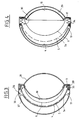
- FIG. 1 and 2 relating to a first embodiment of a cardiac prosthesis total according to the invention.
- This comprises a housing made of a material which is non-toxic to the surrounding tissues, such as a polyurethane, with an upper part and a lower part joined to each other in a sealed manner by suitable means, for example clips 3 placed in a plane perpendicular to the working directions of the motor device.
- This comprises a first membrane 4, made of an elastomer type material, which works at elongation and whose surface is of the order of at least 150 cm2 for a prosthesis with a total bulk of approximately 125 mm but whose surface can be of the order of at least 220 cm2 for a prosthesis of larger dimensions, for example with a total size of 150 mm.
- the membrane 4 delimits with the internal face of the right part of the case which faces it the right ventricle of the prosthesis, of a volume of approximately 250 cm3 and in which is housed a blood bag 19 connected to the pulmonary valve orifices and tricuspid, 14 and 15, respectively, Figure 9, provided with valves, not shown.
- a support piece 5 constituted by a thin veil of rigid material, for example metal or of a reinforced plastic material or unarmed, advantageously pierced with holes 5 a and whose shape is exactly that of the membrane 4 which marries it completely in its non-stretched condition.
- the membrane 4 has, at rest, an ovoid-like shape, with relatively large radii of curvature at the top, in the drawing, that is to say towards the base of the prosthesis where the blood inlet 15 and outlet 14 holes are provided and with smaller radii of curvature towards the tip of the prosthesis, at the bottom in the drawing, this ovoid shape of the membrane combined with the shape of the face internal part of the right part of the wall of the housing giving the right ventricular cavity 17 a shape which widens regularly in the three directions of space, from the tip towards the base of the prosthesis.
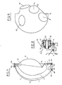
- the holes 5a in the web support 5 whose density is higher in the tip portion than in the rest of said web, as shown schematically in Figure 7, for example, are provided to allow the action on the membrane 4 of a pressurized fluid distributed by a pneumatic energy source connected to the prosthesis, known per se, the inlet and outlet tubing of which is shown in 16 a for the right ventricle and in 16 b for the left ventricle.
- the latter, referenced 18, occupies a volume substantially equal to that of the right ventricle and is limited by the internal face of the left wall of the housing 1, 2 and a partition 9 which extends over the entire height of the prosthesis, the points at the base of the latter.
- the structure of the left ventricle which is very close to that described in the aforementioned French patent, FR-A-2446631, comprises as a motor organ a thin membrane 10 which works for deformation (and not for elongation like the membrane 4) on either side of a plane BB inclined on the longitudinal axial plane of the prosthesis.
- the membrane 10 is fixed laterally on a support 11 made of rigid material, for example stainless steel which limits its deformation to prevent the complete crushing, in the systole phase, of a blood bag 20 housed in the ventricular space 18 and which presents, towards the base of the prosthesis, the blood inlets and outlets corresponding to the valve orifices 12 and 13 of the housing, that is to say the aortic and mitral orifices, respectively.
- the left ventricular space 18 is also of progressively increasing shape in the three directions of space, from the tip towards the base of the prosthesis, such an arrangement having the effect of promoting laminar flows without turbulence and eliminating the zones of zero velocity in said space while favorably orienting the velocity vectors of the blood set in motion towards the aorta.
- the membrane 4 of the right ventricle and the part of the support 5 which is associated with it are not rigidly fixed to the casing of the prosthesis, as in the known prior embodiment, but are secured on their periphery to a flange of end of a bellows whose other end flange is immobilized relative to the housing and / or the longitudinal partition 9 separating, from the point of view of pneumatic energy, the right ventricle of the left centricle.
- the bellows 30 is according to the invention, FIGS. 1 to 4, made of an elastic material, for example of elastomer (natural rubber or neoprene) and of the type with parallel clearance, that is to say arranged so that its turns 31, - compressed at the start of systole ( Figures 1 and 3) -, are spaced from each other over the entire periphery of the bellows at the end of systole ( Figures 2 and 4).
- an elastic material for example of elastomer (natural rubber or neoprene) and of the type with parallel clearance, that is to say arranged so that its turns 31, - compressed at the start of systole ( Figures 1 and 3) -, are spaced from each other over the entire periphery of the bellows at the end of systole ( Figures 2 and 4).
- one of the end flanges 32 of the bellows 30 is crimped by a ring 33 on the partition 9, the membrane 10 and its support 11, while its other end flange 34 is crimped to a ring or ring 35 on the periphery of the membrane 4 and of the support part 5.
- Stop stirrups 36 integral with the ring 33 and advantageously arranged in the housing 1, 2 of the prosthesis, on either side of the plane of symmetry of said housing, have at their ends distant from the flange 32 returns 37 with which is adapted to cooperate the other end flange 34 of the bellows to limit the amplitude of its movement during the systole phase.
- the decomposition of the systole into two phases makes it possible to limit the elongation of the membrane 4 to a value which can be of the order of 7 to 10%, that is to say a value which does not induce in the constituent material of the membrane risks of micro-cracks or the like likely to cause their destruction for a number of operating cycles less than that expected. Notwithstanding the relatively low value of the elongation of the membrane 4, the volume of blood expelled at each pulse is that required by the initial phase of compression of the blood bag during the movement of movement of the bellows 30.
- the motor device can be supplied, from the tubes 16 a and 16 b , in phase or in phase opposition, this latter mode of operation authorizing an energy module of instantaneous lower power and moreover allowing the pressures to be adjusted separately, control of the right ventricle and the left ventricle.
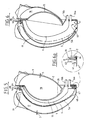
- the bellows 40 associated with the membrane 4 and its support part 5 of the right ventricle is of the pendulum type and no longer with parallel movement as in the previous embodiment. It then comprises turns 41 capable of deviating from one another in the region of the tip of the right ventricle of the prosthesis and a hinge hinge 42 opposite the tip of the prosthesis, that is to say - say in the basic area of it.
- an end flange 43 of the elastic bellows is crimped to the partition 9, the membrane 10 and its support 11, using a ring or ring 44 held in the cells of the housing 1, 2 of the prosthesis, not shown, or by lugs 38, while the opposite end flange 45 is crimped, with the membrane 4 and the support piece 5 in a ring or ring 46.
- Stop stirrups 47, provided with return stops 48 with which is adapted to cooperate the flange 45, are here also provided integral with the ring 44 in the right ventricular space to limit the pendular movement of the bellows 40.
- the presence of a hinge for articulation of the bellows at the base of the prosthesis allows, during the first phase of the systolic movement of the right ventricle, to first cause the emptying of the tip of the blood bag 19, which is the most distant from the articulation hinge, without substantially modifying, simultaneously, the general shape of the ventricular space of the valvular zone during this first phase of systole.
- the higher density of the perforations 5 a of the support piece 5 towards the base of the prosthesis first deforms said membrane in its tip portion, with the consequence of a speeding up of the blood contained in the bag 19 from the tip to the base, favorable for the proper execution of the circulatory phenomenon.
- the fixed end plate is preferably set as shown in figure 6a, that is to say in a ring or ring 33 or 44 which provides, simultaneously, fixing the partition 9, the membrane 10 working on the deformation and the support 11 of said membrane in part 1, 2 of the prosthesis housing, said housing further comprising the tabs 38 for lateral support of said ring 33, 44 and / or stops 36, 47 by their returns.
- the bellows with parallel movement 30 or the pendulum bellows 40 is disposed between the part 2 of the prosthesis housing and the external body 54 limiting the chamber 52, with a fixed and mobile mounting of the flanges of said bellows similar to that described. above.
Abstract
Description
L'invention a pour objet une prothèse cardiaque totale perfectionnée selon le préambule de la revendication 1.The subject of the invention is an improved total cardiac prosthesis according to the preamble of claim 1.
Elle vise, plus particulièrement, une prothèse cardiaque totale de faible encombrement, à source d'activation unique pour les ventricules droit et gauche, présentant une géométrie fonctionnelle qui se rapproche autant que faire se peut de la géométrie fonctionnelle du coeur naturel et qui reproduise les lois de fonctionnement hémodynamique du coeur naturel, en particulier, la loi de STARLING et la loi de SARNOFF.It relates, more particularly, to a total compact cardiac prosthesis, with a single activation source for the right and left ventricles, having a functional geometry which is as close as possible to the functional geometry of the natural heart and which reproduces the laws of hemodynamic functioning of the natural heart, in particular, the law of STARLING and the law of SARNOFF.
Une prothèse de ce type qui s'est révélée d'un fonctionnement satisfaisant, aussi bien lors d'essais in vitro que lors d'essais in vivo sur l'animal est divulguée dans FR-A-2446631. Elle comporte un boîtier implantable dans la cavité péricardique et dont la géométrie reproduit de très près la géométrie d'un coeur naturel avec à l'intérieur de ce boîtier un dispositif moteur essentiellement constitué par deux membranes dont l'une travaille à l'élongation dans un espace définissant le ventricule droit et dont l'autre travaille à la déformation dans un espace définissant le ventricule gauche, le dispositif moteur agissant, respectivement, sur des sacs à sang enfermés dans les espaces ventriculaires droit et gauche. Les sacs à sang sont propres à être reliés aux vaisseaux du réseau circulatoire d'un patient par des valves montées dans des orifices valvulaires ménagés dans le boîtier de la prothèse, celle-ci étant actionnée par des moyens d'activation du dispositif moteur comme une source d'énergie pneumatique extra-corporelle ou un moteur électrique à pile implantable, ou un moteur électrique commandé par une source d'énergie nucléaire, etc..., avec des moyens à boucles d'asservissement de régulation du débit sanguin.A prosthesis of this type which has been found to function satisfactorily, both during in vitro tests and during in vivo tests on animals is disclosed in FR-A-2446631. It comprises a housing implantable in the pericardial cavity and whose geometry very closely reproduces the geometry of a natural heart with inside this housing a motor device essentially constituted by two membranes, one of which works for elongation in a space defining the right ventricle and the other of which works on deformation in a space defining the left ventricle, the motor device acting, respectively, on blood bags enclosed in the right and left ventricular spaces. The blood bags are suitable for being connected to the vessels of the circulatory network of a patient by valves mounted in valvular orifices formed in the housing of the prosthesis, the latter being actuated by means of activation of the motor device like a source of extracorporeal pneumatic energy or an electric motor with an implantable battery, or an electric motor controlled by a nuclear energy source, etc., with means with control loops for regulating blood flow.
Comme décrit dans le Brevet précité, la membrane du dispositif moteur du ventricule droit de la prothèse, à laquelle est associé un support, est une membrane en un matériau élastomère soumise à des allongements alternatifs au cours d'un très grand nombre de cycles de déformation en élongation, de sorte que peuvent apparaître, après plusieurs dizaines de millions d'alternances, des altérations comme des micro-fissures qui, à la longue, peuvent entraîner sa destruction.As described in the aforementioned patent, the membrane of the motor device of the right ventricle of the prosthesis, with which a support is associated, is a membrane of an elastomeric material subjected to alternative elongations during a very large number of deformation cycles. in elongation, so that there may appear, after several tens of millions of alternations, alterations such as micro-cracks which, in the long run, can lead to its destruction.
Aussi le problème se pose-t-il de fournir une prothèse cardiaque totale du type de celle décrite ci-dessus, dont la membrane du ventricule droit ait une durée de vie aussi longue que possible, en tout cas supérieure à deux cent cinquante millions de cycles et qui, cependant, permette de satisfaire aux autres conditions imposées au dispositif moteur de la prothèse, en particulier assurer à chaque pulsation l'éjection d'un volume compris entre 60 et 90 ml de sang. Etant donné, d'une part, que pour une membrane d'une certaine surface ce volume utile est directement lié à l'allongement de la membrane et que, d'autre part, l'allongement maximum conditionne le nombre de cycles auxquels peut être soumise ladite membrane sans apparition de micro-fissures, le problème posé est alors celui de fournir dans le dispositif moteur de la prothèse un agencement de membrane procurant la variation de volume souhaité pour un allongement aussi faible que possible.The problem therefore arises of providing a total cardiac prosthesis of the type described above, the membrane of the right ventricle of which has a lifespan as long as possible, in any case greater than two hundred and fifty million cycles and which, however, makes it possible to satisfy the other conditions imposed on the motor device of the prosthesis, in particular to ensure at each pulse the ejection of a volume of between 60 and 90 ml of blood. Given, on the one hand, that for a membrane of a certain surface this useful volume is directly linked to the elongation of the membrane and that, on the other hand, the maximum elongation conditions the number of cycles to which can be subject said membrane without the appearance of micro-cracks, the problem then is that of providing in the prosthesis drive device a membrane arrangement providing the desired volume variation for as little elongation as possible.
Ce problème est résolu, selon l'invention, par le fait que la membrane élastique du ventricule droit et la pièce de support qui lui est associée sont montées dans le boîtier de la prothèse à l'aide de moyens agencés de manière telle que le mouvement de ladite membrane à l'élongation (systole) est décomposé en deux phases, dont l'une est un déplacement sans allongement et dont l'autre, seulement,est accompagnée d'un allongement tandis que le mouvement inverse (diastole) comprend d'abord une phase de rétraction suivie d'un déplacement sans modification de forme de ladite membrane et de la pièce support qui lui est associée.This problem is solved, according to the invention, by the fact that the elastic membrane of the right ventricle and the support piece which is associated with it are mounted in the prosthesis housing using means arranged in such a way that the movement of said elongated membrane (systole) is broken down into two phases, one of which is a displacement without elongation and the other, only, is accompanied by an elongation while the reverse movement (diastole) comprises first a phase of retraction followed by a displacement without modification of the shape of said membrane and of the support part which is associated with it.
Avec une telle disposition, l'allongement de la membrane du ventricule droit du dispositif moteur est limité à une valeur d'élongation inférieure à 8 à 10% de sorte que les efforts de fatigue sont considérablement réduits avec, pour conséquence, un maintien de l'intégrité de la membrane pour au moins deux cent cinquante millions de cycles de fonctionnement.With such an arrangement, the elongation of the membrane of the right ventricle of the motor device is limited to an elongation value of less than 8 to 10% so that the fatigue forces are considerably reduced with, as a consequence, maintenance of the integrity of the membrane for at least two hundred and fifty million operating cycles.
Dans une forme de réalisation, les moyens procurant la décomposition en deux phases du mouvement de la membrane du ventricule droit comprennent au moins un soufflet propre à être relié à la source d'énergie pneumatique et sur lequel sont fixées la membrane et la pièce de support qui lui est associée.In one embodiment, the means providing the decomposition in two phases of the movement of the membrane of the right ventricle comprise at least one bellows suitable for being connected to the source of pneumatic energy and on which the membrane and the support piece are fixed. associated with it.
Dans un mode d'exécution, le soufflet est du type à déplacement parallèle.In one embodiment, the bellows is of the parallel displacement type.
Dans une variante, le soufflet est du type à déplacement pendulaire.In a variant, the bellows is of the pendulum displacement type.
Dans l'un et l'autre mode d'exécution, l'invention prévoit que le soufflet soit lui-même réalisé en un matériau élastique et que son extrémité, distante de celle de fixation de la membrane et de la pièce support qui lui est associée, soit fixée par sertissage à une cloison étanche séparant les espaces ventriculaires droit et gauche de la prothèse,cloison sur laquelle est également fixée la membrane travaillant à la déformation du ventricule gauche.In both embodiments, the invention provides that the bellows is itself made of an elastic material and that its end, distant from that for fixing the membrane and the support part which is attached to it. associated, either fixed by crimping to a watertight partition separating the right and left ventricular spaces of the prosthesis, partition on which is also fixed the membrane working on the deformation of the left ventricle.
Selon une autre caractéristique de l'invention, la phase de déplacement sans allongement de la membrane travaillant à l'élongation du ventricule droit est limitée, à l'élongation de ladite membrane (systole), par butée sur un organe d'arrêt de l'extrémité mobile du soufflet sur laquelle est attachée ladite membrane et la pièce de support qui lui est associée.According to another characteristic of the invention, the phase of displacement without elongation of the membrane working for the elongation of the right ventricle is limited, to the elongation of said membrane (systole), by abutment on a stop member of the movable end of the bellows on which said membrane and the supporting part associated with it are attached.
Une telle organisation du ventricule droit permet en outre de réduire la puissance motrice de la source d'énergie pneumatique, par rapport à celle de la prothèse connue, en raison de la moindre quantité d'énergie nécessaire pour l'actionnement de la membrane dudit ventricule dont on prévoit complémentairement d'aider le mouvement inverse de retour à la forme initiale qui lui est donnée par moulage ―, qui est celle qui correspond au début de systole ―, par une légère dépression pneumatique.Such an organization of the right ventricle also makes it possible to reduce the motive power of the pneumatic energy source, compared with that of the known prosthesis, due to the lower amount of energy required for actuating the membrane of said ventricle. which is also intended to assist the reverse movement back to the initial shape given to it by molding - which is that which corresponds to the start of systole - by a slight pneumatic depression.
Au bon fonctionnement de la prothèse contribue la présence d'un lubrifiant sec ou liquide entre les sacs à sang, le boîtier de la prothèse, les membranes du dispositif moteur et les moyens associés à la membrane du ventricule droit pour la décomposition du mouvement de celle-ci en deux phases distinctes.The proper functioning of the prosthesis contributes to the presence of a dry or liquid lubricant between the blood bags, the prosthesis case, the membranes of the motor device and the means associated with the membrane of the right ventricle for the decomposition of the movement of that - in two distinct phases.
La forme générale du boîtier et celle des espaces ventriculaires droit et gauche sont proches de celles de la prothèse selon le Brevet français précité, de sorte que lesdits espaces ventriculaires à dimensions croissantes, de la pointe vers la base de la prothèse, favorisent une bonne orientation des vecteurs vitesse du sang mis en mouvement vers les orifices valvulaires de sortie, sans zone de stase.The general shape of the housing and that of the right and left ventricular spaces are close to those of the prosthesis according to the aforementioned French patent, so that said ventricular spaces with increasing dimensions, from the point towards the base of the prosthesis, favor a good orientation. velocity vectors of the blood set in motion towards the valve outlet orifices, without zone of stasis.
Le mode d'exécution a soufflet pendulaire accroît encore l'effet favorable de la géométrie d'ensemble de la prothèse par le fait qu'elle provoque d'abord le vidage de la pointe du sac à sang du ventricule droit et cela à une plus grande vitesse que le vidage du reste du sac, ― en raison du plus grand éloignement de cette pointe de la charnière d'articulation du mouvement pendulaire ―, sans modification toutefois de la vitesse du sang à l'orifice valvulaire, d'une part, et, d'autre part, la poursuite dans les conditions habituelles du vidage du sac lorsque, à la fin de la première phase de mouvement de la membrane du ventricule droit, celle-ci commence à travailler à l'élongation, uniquement.The pendulum bellows embodiment further increases the favorable effect of the overall geometry of the prosthesis by the fact that it first causes the emptying of the tip of the blood bag of the right ventricle and this at a higher speed than the emptying of the rest of the bag, - due to the greater distance of this tip from the hinge of articulation of the pendular movement -, without however modifying the speed of the blood at the valvular opening, on the one hand, and, on the other hand, the continuation under the usual conditions of the emptying of the bag when, at the end of the first phase of movement of the membrane of the right ventricle, that -this starts working on stretching only.
L'invention sera bien comprise par la description qui suit, faite à titre d'exemple et en référence au dessin annexé dans lequel:
- ― la figure 1 est une vue schématique, en coupe longitudinale, d'une prothèse cardiaque totale conforme à l'invention;
- ― la figure 2 est une vue analogue à celle de la figure 1 mais pour une autre condition du dispositif moteur;
- ― la figure 3 est une vue schématique en coupe transversale de la prothèse dans la condition montrée sur la figure 1;
- ― la figure 4 est une vue en coupe transversale de la prothèse dans la condition montrée sur la figure 2;
- ― la figure 5 est une vue analogue à celle de la figure 1 mais pour une autre forme de réalisation;
- ― la figure 6 est une vue de cette forme de réalisation mais pour une autre condition du dispositif moteur;
- ― la figure 6a est une vue de détail des réalisations montrées sur les figures 1 à 4 et 5 et 6;
- ― la figure 7 est une vue schématique d'un dispositif moteur de prothèse perfectionnée selon l'invention;
- ― la figure 8 est une vue de détail;
- ― la figure 9 est une vue schématique en perspective du boîtier de la prothèse conforme à l'invention comportant quatre orifices valvulaires.
- - Figure 1 is a schematic view, in longitudinal section, of a total cardiac prosthesis according to the invention;
- - Figure 2 is a view similar to that of Figure 1 but for another condition of the motor device;
- - Figure 3 is a schematic cross-sectional view of the prosthesis in the condition shown in Figure 1;
- - Figure 4 is a cross-sectional view of the prosthesis in the condition shown in Figure 2;
- - Figure 5 is a view similar to that of Figure 1 but for another embodiment;
- - Figure 6 is a view of this embodiment but for another condition of the motor device;
- - Figure 6a is a detail view of the embodiments shown in Figures 1 to 4 and 5 and 6;
- - Figure 7 is a schematic view of an improved prosthesis drive device according to the invention;
- - Figure 8 is a detail view;
- - Figure 9 is a schematic perspective view of the prosthesis housing according to the invention comprising four valve orifices.
On se réfère d'abord aux figures 1 et 2 relatives à une première forme de réalisation d'une prothèse cardiaque totale selon l'invention. Celle-ci comprend un boîtier réalisé en un matériau non toxique à l'égard des tissus environnants, comme un polyuréthanne, avec une partie supérieure et une partie inférieure réunies l'une à l'autre d'une façon étanche par des moyens appropriés, par exemple des clips 3 placés dans un plan perpendiculaire aux directions de travail du dispositif moteur. Celui-ci comprend une première membrane 4, en matériau du type élastomère, qui travaille à l'élongation et dont la surface est de l'ordre d'au moins 150 cm² pour une prothèse d'un encombrement total d'environ 125 mm mais dont la surface peut être de l'ordre d'au moins 220 cm² pour une prothèse de plus grandes dimensions, par exemple d'un encombrement total de 150 mm.We first refer to Figures 1 and 2 relating to a first embodiment of a cardiac prosthesis total according to the invention. This comprises a housing made of a material which is non-toxic to the surrounding tissues, such as a polyurethane, with an upper part and a lower part joined to each other in a sealed manner by suitable means, for
La membrane 4 délimite avec la face interne de la partie droite du boîtier qui lui fait face le ventricule droit de la prothèse, d'un volume d'environ 250 cm³ et dans lequel est logé un sac à sang 19 relié aux orifices valvulaires pulmonaire et tricuspide, 14 et 15, respectivement, figure 9, munis de valves, non représentées. Dans sa condition de repos, c'est-à-dire en absence totale d'élongation, la membrane 4 repose sur une pièce de support 5 constituée par un voile mince en matériau rigide, par exemple en métal ou en une matière plastique armée ou non armée, avantageusement percé de trous 5a et dont la forme est exactement celle de la membrane 4 qui l'épouse totalement dans sa condition non tendue. Comme bien montré sur les figures 1 et 5 la membrane 4 présente, au repos, une forme d'allure ovoïde, à rayons de courbure relativement grands en partie haute, sur le dessin, c'est-à-dire vers la base de la prothèse où sont prévus les orifices d'entrée 15 et de sortie 14 du sang et à rayons de courbure plus faibles vers la pointe de la prothèse, en partie basse sur le dessin, cette forme ovoïde de la membrane combinée à la forme de la face interne de la partie droite de la paroi du boîtier conférant à la cavité ventriculaire droite 17 une forme qui s'élargit régulièrement dans les trois directions de l'espace, de la pointe vers la base de la prothèse.The
Les orifices 5a dans le voile de soutien 5 dont la densité est plus forte dans la partie de pointe que dans le reste dudit voile, comme montré schématiquement sur la figure 7, par exemple, sont prévus pour permettre l'action sur la membrane 4 d'un fluide sous pression distribué par une source d'énergie pneumatique reliée à la prothèse, en soi connue, dont la tubulure d'entrée et de sortie est montrée en 16a pour le ventricule droit et en 16b pour le ventricule gauche. Ce dernier, référencé 18, occupe un volume sensiblement égal à celui du ventricule droit et est limité par la face interne de la paroi gauche du boîtier 1, 2 et une cloison 9 qui s'étend sur toute la hauteur de la prothèse, de la pointe à la base de cette dernière.The
La structure du ventricule gauche, qui est très proche de celle décrite dans le Brevet français précité, FR-A-2446631, comporte en tant qu'organe moteur une membrane mince 10 qui travaille à la déformation (et non à l'élongation comme la membrane 4) de part et d'autre d'un plan B-B incliné sur le plan axial longitudinal de la prothèse. La membrane 10 est fixée latéralement sur un support 11 en matériau rigide, par exemple en acier inoxydable qui limite sa déformation pour empêcher l'écrasement complet, en phase de systole, d'un sac à sang 20 logé dans l'espace ventriculaire 18 et qui présente, vers la base de la prothèse, les entrées et sorties de sang correspondant aux orifices valvulaires 12 et 13 du boîtier, c'est-à-dire les orifices aortique et mitral, respectivement. L'espace ventriculaire gauche 18 est lui aussi de forme progressivement croissante dans les trois directions de l'espace, de la pointe vers la base de la prothèse, une telle disposition ayant pour effet de favoriser des écoulements laminaires sans turbulence et d'éliminer les zones de vitesse nulle dans ledit espace tout en orientant de façon favorable les vecteurs vitesse du sang mis en mouvement vers l'aorte.The structure of the left ventricle, which is very close to that described in the aforementioned French patent, FR-A-2446631, comprises as a motor organ a
Selon l'invention, la membrane 4 du ventricule droit et la pièce du support 5 qui lui est associée ne sont pas fixées rigidement au boîtier de la prothèse, comme dans la réalisation antérieure connue, mais sont solidarisées sur leur périphérie à un flasque d'extrémité d'un soufflet dont l'autre flasque d'extrémité est immobilisé par rapport au boîtier et/ou la cloison longitudinale 9 séparant, du point de vue de l'énergie pneumatique, le ventricule droit du centricule gauche.According to the invention, the
Dans une première réalisation, le soufflet 30 est selon l'invention, figures 1 à 4, en un matériau élastique, par exemple en élastomère (caoutchouc naturel ou néoprène) et du type à débattement parallèle, c'est-à-dire agencé de manière que ses spires 31, ― comprimées en début de systole (figures 1 et 3) ―, sont écartées les unes des autres sur la totalité de la périphérie de soufflet en fin de systole (figures 2 et 4). De façon plus précise, un des flasques d'extrémité 32 du soufflet 30 est serti par un anneau 33 sur la cloison 9, la membrane 10 et son support 11, tandis que son autre flasque d'extrémité 34 est serti à un anneau ou bague 35 sur la périphérie de la membrane 4 et de la pièce de support 5.In a first embodiment, the
Des étriers de butée 36, solidaires de l'anneau 33 et avantageusement disposés dans le boîtier 1, 2 de la prothèse, de part et d'autre du plan de symétrie dudit boîtier, présentent à leurs extrémités distantes du flasque 32 des retours 37 avec lesquels est propre à coopérer l'autre flasque d'extrémité 34 du soufflet pour limiter l'amplitude de son débattement lors de la phase de systole. Au début de celle-ci, la condition de la prothèse est celle montrée sur les figures 1 et 3; l'introduction de fluide sous pression par la tubulure 16a provoque d'abord le déplacement de la membrane 4 et de la pièce de soutien 5 qui lui est associée, avec compression concomitante du sac à sang 19, jusqu'à butée du flasque 34 sur les arrêts 37 puis, à partir de cette position, une augmentation de la pression du fluide moteur entraîne l'élongation de la membrane 4 pour parachever la phase systolique du ventricule droit jusqu'à vidage total du sac à sang.Stop
La décomposition de la systole en deux phases permet de limiter l'élongation de la membrane 4 à une valeur qui peut être de l'ordre de 7 à 10%, c'est-à-dire une valeur qui n'induit pas dans le matériau constitutif de la membrane des risques de micro-fissures ou analogues susceptibles d'en provoquer la destruction pour un nombre de cycles de fonctionnement inférieur à celui escompté. Nonobstant la valeur relativement faible de l'allongement de la membrane 4, le volume de sang expulsé à chaque pulsation est celui requis grâce à la phase initiale de compression du sac à sang lors du mouvement de débattement du soufflet 30.The decomposition of the systole into two phases makes it possible to limit the elongation of the
Le dispositif moteur peut être alimenté, à partir des tubulures 16a et 16b, en phase ou en opposition de phase, ce dernier mode de fonctionnement autorisant un module énergétique de moindre puissance instantanée et permettant en outre de mieux régler, séparément, les pressions de commande du ventricule droit et du ventricule gauche.The motor device can be supplied, from the
Dans un second mode de réalisation, figures 5 à 7, le soufflet 40 associé à la membrane 4 et à sa pièce support 5 du ventricule droit est du type pendulaire et non plus à débattement parallèle comme dans la réalisation précédente. Il comprend alors des spires 41 susceptibles de s'écarter les unes des autres dans la zone de la pointe du ventricule droit de la prothèse et une charnière d'articulation 42 à l'opposé de la pointe de la prothèse, c'est-à-dire dans la zone de base de celle-ci. Comme dans la réalisation précédente, un flasque d'extrémité 43 du soufflet élastique est serti à la cloison 9, la membrane 10 et son support 11, à l'aide d'une bague ou anneau 44 maintenu dans les alvéoles du boîtier 1, 2 de la prothèse, non représentés, ou par des pattes 38, tandis que le flasque d'extrémité opposé 45 est serti, avec la membrane 4 et la pièce de support 5 dans une bague ou anneau 46. Des étriers de butée 47, munis de retour d'arrêts 48 avec lesquels est propre à coopérer le flasque 45, sont ici aussi prévus solidaires de l'anneau 44 dans l'espace ventriculaire droit pour limiter le mouvement pendulaire du soufflet 40. Dans une telle réalisation, dont le fonctionnement est pour le reste analogue à celui décrit ci-dessus, la présence d'une charnière d'articulation du soufflet à la base de la prothèse permet, lors de la première phase du mouvement systolique du ventricule droit, de provoquer d'abord le vidage de la pointe du sac à sang 19, qui est la plus distante de la charnière d'articulation, sans modifier sensiblement, simultanément, la forme générale de l'espace ventriculaire de la zone valvulaire au cours de cette première phase de la systole. Au cours de la seconde phase, c'est-à-dire celle qui comporte une élongation de la membrane 4, la densité plus importante des perforations 5a de la pièce de support 5 vers la base de la prothèse déforme d'abord ladite membrane dans sa partie de pointe, avec pour conséquence une mise en vitesse du sang contenu dans le sac 19 de la pointe vers la base, favorable à la bonne exécution du phénomène circulatoire.In a second embodiment, Figures 5 to 7, the
Dans l'une et l'autre réalisations décrites ci-dessus le flasque d'extrémité fixe est avantageusement serti comme montré sur la figure 6a, c'est-à-dire dans une bague ou anneau 33 ou 44 qui assure, simultanément, la fixation de la cloison 9, de la membrane 10 travaillant à la déformation et du support 11 de ladite membrane dans la partie 1, 2 du boîtier de la prothèse, ledit boîtier comportant en outre les pattes 38 de maintien latéral dudit anneau 33, 44 et/ou des butées 36, 47 par leurs retours.In one and the other embodiments described above the fixed end plate is preferably set as shown in figure 6a, that is to say in a ring or
Alors que dans les deux réalisations décrites ci-dessus les tubulures 16a et 16b de liaison du dispositif moteur à la source du fluide sous pression sont disposées parallèlement l'une à l'autre, il peut être avantageux,dans certaines réalisations, de prévoir des raccords concentriques et non plus parallèles. Dans une telle réalisation, figure 8, c'est le forage central 50 d'une pièce 51, placée à la pointe de la prothèse, qui joue le rôle de tubulure 16a, le rôle de la tubulure 16b étant assuré par une chambre annulaire 52 entourant le forage 50 et qui communique par un ou des passage(s) 53 avec l'espace limité par la cloison 9 et la membrane 10 travaillant à la déformation. Dans cette réalisation, le soufflet à débattement parallèle 30 ou le soufflet pendulaire 40 est disposé entre la partie 2 du boîtier de la prothèse et le corps 54 externe limitant la chambre 52, avec un montage des flasques fixe et mobile dudit soufflet analogue à celui décrit ci-dessus.While in the two embodiments described above the
Claims (12)
Priority Applications (1)
| Application Number | Priority Date | Filing Date | Title |
|---|---|---|---|
| AT88901281T ATE66619T1 (en) | 1987-01-27 | 1988-01-27 | TOTAL HEART PROSTHESIS. |
Applications Claiming Priority (2)
| Application Number | Priority Date | Filing Date | Title |
|---|---|---|---|
| FR8700908 | 1987-01-27 | ||
| FR8700908A FR2609886B1 (en) | 1987-01-27 | 1987-01-27 | TOTAL IMPROVED HEART PROSTHESIS |
Publications (2)
| Publication Number | Publication Date |
|---|---|
| EP0300012A1 EP0300012A1 (en) | 1989-01-25 |
| EP0300012B1 true EP0300012B1 (en) | 1991-08-28 |
Family
ID=9347294
Family Applications (1)
| Application Number | Title | Priority Date | Filing Date |
|---|---|---|---|
| EP88901281A Expired - Lifetime EP0300012B1 (en) | 1987-01-27 | 1988-01-27 | Improved total heart prosthesis |
Country Status (7)
| Country | Link |
|---|---|
| US (1) | US5089018A (en) |
| EP (1) | EP0300012B1 (en) |
| JP (1) | JPH01502564A (en) |
| AT (1) | ATE66619T1 (en) |
| DE (1) | DE3864471D1 (en) |
| FR (1) | FR2609886B1 (en) |
| WO (1) | WO1988005313A1 (en) |
Families Citing this family (9)
| Publication number | Priority date | Publication date | Assignee | Title |
|---|---|---|---|---|
| US5300111A (en) * | 1992-02-03 | 1994-04-05 | Pyxis, Inc. | Total artificial heart |
| US5314469A (en) * | 1992-03-11 | 1994-05-24 | Milwaukee Heart Research Foundation | Artificial heart |
| DE69419420T2 (en) * | 1993-09-10 | 1999-11-18 | Ottawa Heart Inst Research Cor | ELECTROHYDRAULIC VENTRICULAR SUPPORT SYSTEM |
| JP4485208B2 (en) * | 2002-02-21 | 2010-06-16 | デザイン・メンター・インコーポレイテッド | Fluid pump |
| ITUD20050112A1 (en) * | 2005-07-01 | 2007-01-02 | Gaetano Azzolina | CARDIOCIRCULATORY ASSISTANCE DEVICE |
| US20070083077A1 (en) | 2005-10-06 | 2007-04-12 | Alpha Dev, Llc. | Total artificial heart system for auto-regulating flow and pressure balance |
| DE102008017448A1 (en) * | 2008-04-05 | 2009-10-08 | Deutsches Zentrum für Luft- und Raumfahrt e.V. | Heart assist device |
| US8226712B1 (en) | 2008-06-13 | 2012-07-24 | Newheart Medical Devices Llc | Total artificial heart system for auto-regulating flow and pressure |
| CN103330964B (en) * | 2013-05-31 | 2015-08-26 | 上海交通大学 | With the artificial heart system of blood pressure regulating mechanism |
Family Cites Families (10)
| Publication number | Priority date | Publication date | Assignee | Title |
|---|---|---|---|---|
| GB1079211A (en) * | 1964-04-22 | 1967-08-16 | Distillers Co Yeast Ltd | Improvements in or relating to diaphragm pumps |
| US4222127A (en) * | 1978-06-02 | 1980-09-16 | Donachy And Pierce | Blood pump and method of pumping blood |
| FR2470593A2 (en) * | 1979-01-22 | 1981-06-12 | Lapeyre Didier | NEW TOTAL HEART PROSTHESIS |
| US4427470A (en) * | 1981-09-01 | 1984-01-24 | University Of Utah | Vacuum molding technique for manufacturing a ventricular assist device |
| FR2519544A1 (en) * | 1982-01-11 | 1983-07-18 | Casile Jean Pierre | CIRCULATORY ASSISTANCE DEVICE |
| US4652265A (en) * | 1982-09-23 | 1987-03-24 | Mcdougall David A | Implantable blood pump and integral apparatus for the operation thereof |
| US4573997A (en) * | 1984-03-19 | 1986-03-04 | Research Corporation | Right ventricular assist device |
| FR2572491B1 (en) * | 1984-10-31 | 1987-07-03 | Aerospatiale | SYSTEM FOR THE INDIVIDUAL COMMUNICATION WITH THE OUTSIDE OF TWO CONTIGUOUS ENCLOSURES AND HEART PROSTHESIS PROVIDED WITH SUCH A SYSTEM |
| US4781715A (en) * | 1986-04-30 | 1988-11-01 | Temple University Of The Commonwealth System Of Higher Education | Cardiac prosthesis having integral blood pressure sensor |
| US4781716A (en) * | 1987-02-13 | 1988-11-01 | Marc Richelsoph | Artificial heart |
-
1987
- 1987-01-27 FR FR8700908A patent/FR2609886B1/en not_active Expired
-
1988
- 1988-01-27 US US07/264,951 patent/US5089018A/en not_active Expired - Fee Related
- 1988-01-27 JP JP62506282A patent/JPH01502564A/en active Pending
- 1988-01-27 EP EP88901281A patent/EP0300012B1/en not_active Expired - Lifetime
- 1988-01-27 DE DE8888901281T patent/DE3864471D1/en not_active Expired - Lifetime
- 1988-01-27 WO PCT/FR1988/000043 patent/WO1988005313A1/en active IP Right Grant
- 1988-01-27 AT AT88901281T patent/ATE66619T1/en active
Also Published As
| Publication number | Publication date |
|---|---|
| WO1988005313A1 (en) | 1988-07-28 |
| FR2609886A1 (en) | 1988-07-29 |
| FR2609886B1 (en) | 1989-07-28 |
| DE3864471D1 (en) | 1991-10-02 |
| US5089018A (en) | 1992-02-18 |
| JPH01502564A (en) | 1989-09-07 |
| ATE66619T1 (en) | 1991-09-15 |
| EP0300012A1 (en) | 1989-01-25 |
Similar Documents
| Publication | Publication Date | Title |
|---|---|---|
| EP0014130B1 (en) | Complete cardiac prosthesis and device for regulating the blood flow rate therein | |
| EP0300012B1 (en) | Improved total heart prosthesis | |
| EP0959912B1 (en) | Pressure generator for a counterpressure cardiac assistance device | |
| EP2152570B1 (en) | Submersible apparatus including flexible waterproofing membranes | |
| EP0739451B1 (en) | Micropump | |
| EP0349377B1 (en) | Microelectric switch valve with one single diaphragm | |
| EP2121116B1 (en) | Connector for a establishing a fluid communication controlled by a valve, essentially used in the field of medicine | |
| FR2916980A1 (en) | IMPLANTABLE SITE WITH ACCESS REDISTRIBUTION SCREEN | |
| FR2508320A1 (en) | BLOOD PUMP | |
| EP0429591A1 (en) | Improved micro-pump. | |
| FR2773995A1 (en) | IMPLANTABLE BLOOD PUMP AND METHOD FOR BLOOD SUPPLY OF THE CIRCULATORY SYSTEM OF A PATIENT | |
| CH678277A5 (en) | ||
| FR2542994A1 (en) | FULLY IMPLANTABLE MANUALLY ACTUATED DEVICE FOR PENIS ERECTION, AND METHOD FOR IMPLANTATION | |
| WO1997023255A1 (en) | Catheter having a valve with bidirectional axial slits | |
| EP0148661B1 (en) | Implantable blood pump | |
| EP2078533B1 (en) | Implantable single-piece artificial heart | |
| EP0505270B1 (en) | Implantable blood pump | |
| FR2591489A1 (en) | TOTAL CARDIAC PROSTHESIS COMPRISING TWO PUMPING MODULES CONNECTED BY A FUNCTIONAL CONNECTION. | |
| CA2162585A1 (en) | Method of training a skeletal muscle for a biomechanical heart and biomechanical heart using said muscle | |
| EP1867352A1 (en) | Anatomically implantable heart prosthesis in one piece | |
| FR2760973A1 (en) | TOTALLY IMPLANTABLE ARTIFICIAL HEART | |
| EP0227537B1 (en) | Total cardiac prosthesis with two separate pumps operating as an inseparable unit | |
| EP2854742B1 (en) | Device for stimulating the genital or erogenous areas of a person | |
| EP4308215A1 (en) | Device for assistance by direct cardiac compression | |
| FR2520459A1 (en) | JOINT FLEXIBLE FOR JOINT |
Legal Events
| Date | Code | Title | Description |
|---|---|---|---|
| PUAI | Public reference made under article 153(3) epc to a published international application that has entered the european phase |
Free format text: ORIGINAL CODE: 0009012 |
|
| 17P | Request for examination filed |
Effective date: 19881006 |
|
| AK | Designated contracting states |
Kind code of ref document: A1 Designated state(s): AT BE CH DE FR GB IT LI LU NL SE |
|
| 17Q | First examination report despatched |
Effective date: 19901023 |
|
| GRAA | (expected) grant |
Free format text: ORIGINAL CODE: 0009210 |
|
| AK | Designated contracting states |
Kind code of ref document: B1 Designated state(s): AT BE CH DE FR GB IT LI LU NL SE |
|
| PG25 | Lapsed in a contracting state [announced via postgrant information from national office to epo] |
Ref country code: SE Effective date: 19910828 Ref country code: NL Effective date: 19910828 Ref country code: AT Effective date: 19910828 |
|
| REF | Corresponds to: |
Ref document number: 66619 Country of ref document: AT Date of ref document: 19910915 Kind code of ref document: T |
|
| REF | Corresponds to: |
Ref document number: 3864471 Country of ref document: DE Date of ref document: 19911002 |
|
| ITF | It: translation for a ep patent filed |
Owner name: STUDIO TORTA SOCIETA' SEMPLICE |
|
| GBT | Gb: translation of ep patent filed (gb section 77(6)(a)/1977) | ||
| PG25 | Lapsed in a contracting state [announced via postgrant information from national office to epo] |
Ref country code: LU Free format text: LAPSE BECAUSE OF NON-PAYMENT OF DUE FEES Effective date: 19920131 Ref country code: BE Effective date: 19920131 |
|
| NLV1 | Nl: lapsed or annulled due to failure to fulfill the requirements of art. 29p and 29m of the patents act | ||
| PLBE | No opposition filed within time limit |
Free format text: ORIGINAL CODE: 0009261 |
|
| STAA | Information on the status of an ep patent application or granted ep patent |
Free format text: STATUS: NO OPPOSITION FILED WITHIN TIME LIMIT |
|
| BERE | Be: lapsed |
Owner name: LAPEYRE DIDIER Effective date: 19920131 |
|
| 26N | No opposition filed | ||
| PG25 | Lapsed in a contracting state [announced via postgrant information from national office to epo] |
Ref country code: FR Effective date: 19920930 |
|
| REG | Reference to a national code |
Ref country code: FR Ref legal event code: ST |
|
| PGFP | Annual fee paid to national office [announced via postgrant information from national office to epo] |
Ref country code: CH Payment date: 19951222 Year of fee payment: 9 |
|
| PGFP | Annual fee paid to national office [announced via postgrant information from national office to epo] |
Ref country code: GB Payment date: 19960118 Year of fee payment: 9 |
|
| PGFP | Annual fee paid to national office [announced via postgrant information from national office to epo] |
Ref country code: DE Payment date: 19960122 Year of fee payment: 9 |
|
| PG25 | Lapsed in a contracting state [announced via postgrant information from national office to epo] |
Ref country code: GB Effective date: 19970127 |
|
| PG25 | Lapsed in a contracting state [announced via postgrant information from national office to epo] |
Ref country code: LI Effective date: 19970131 Ref country code: CH Effective date: 19970131 |
|
| REG | Reference to a national code |
Ref country code: CH Ref legal event code: PL |
|
| GBPC | Gb: european patent ceased through non-payment of renewal fee |
Effective date: 19970127 |
|
| PG25 | Lapsed in a contracting state [announced via postgrant information from national office to epo] |
Ref country code: DE Effective date: 19971001 |
|
| PG25 | Lapsed in a contracting state [announced via postgrant information from national office to epo] |
Ref country code: IT Free format text: LAPSE BECAUSE OF NON-PAYMENT OF DUE FEES Effective date: 20050127 |