EP0299501A1 - Device for scoring and fracturing ceramic tiles - Google Patents
Device for scoring and fracturing ceramic tiles Download PDFInfo
- Publication number
- EP0299501A1 EP0299501A1 EP88111376A EP88111376A EP0299501A1 EP 0299501 A1 EP0299501 A1 EP 0299501A1 EP 88111376 A EP88111376 A EP 88111376A EP 88111376 A EP88111376 A EP 88111376A EP 0299501 A1 EP0299501 A1 EP 0299501A1
- Authority
- EP
- European Patent Office
- Prior art keywords
- scoring
- fracturing
- ceramic tiles
- tile
- bridge guide
- Prior art date
- Legal status (The legal status is an assumption and is not a legal conclusion. Google has not performed a legal analysis and makes no representation as to the accuracy of the status listed.)
- Granted
Links
Images


Classifications
-
- B—PERFORMING OPERATIONS; TRANSPORTING
- B28—WORKING CEMENT, CLAY, OR STONE
- B28D—WORKING STONE OR STONE-LIKE MATERIALS
- B28D1/00—Working stone or stone-like materials, e.g. brick, concrete or glass, not provided for elsewhere; Machines, devices, tools therefor
- B28D1/22—Working stone or stone-like materials, e.g. brick, concrete or glass, not provided for elsewhere; Machines, devices, tools therefor by cutting, e.g. incising
- B28D1/225—Working stone or stone-like materials, e.g. brick, concrete or glass, not provided for elsewhere; Machines, devices, tools therefor by cutting, e.g. incising for scoring or breaking, e.g. tiles
Definitions
- the present invention relates to a device for scoring and fracturing ceramic tiles.
- the invention as claimed is intended to remedy these drawbacks.
- the inventor with ingenious perception has conceived a series of arrangements which, from one side, maintain the professional level of the tile cutter, even increasing its adaptability in use and on the other hand such improvements are the result of simplifications involving an easier manufacturing technology and accommodation of loads.
- Such accommodation of loads favours a structure lightening which, at least at parity of other characteristics, results in a decrease of weight comprised between 30%, for models of smaller size to 50% for models of larger size Reduction substantially of the same order results in the manufacturing and sale cost.
- Original and radical improvements have been made to the self adjusting arrangement providing device for weakly and heavily fastening an fracturing of tile including a vertical fixed position of one end of the bridge guide.
- a so profiled cam provide an easy and control over tiles of various thickness.
- a device for scoring and fracturing ceramic tiles comprises, conventionally, a base 1, possibly embodying a graduated gauge bar 1′, from which project: at least a wedge 10 and a rib 10′, as well as two uprights 11, 11′; 12, placed at the ends thereof.
- a bridge guide 2 provided by two parallel rods 2′ and 2 ⁇ , wherein a tool 3, is shiftably mounted therealong, a handle 3′, a follower 3 ⁇ , in the form of handle-bar, a substantially rodlike body 30, and at the bottom thereof a disk or cutter 31.
- a pressure means 33 Fastened to the bridge guide 2, there is a pressure means 33, provided by a pair of fins 33′, 22 ⁇ .
- An antagonist fixed handle 4 is attached to the base in line with the bridge guide 2 and projecting outwardly, therefrom.
- a movable handle 40 Substantially placed above to the fixed handle 4, there is a movable handle 40, which is swingable and cooperates with the bridge guide 2.
- the resilient pads 15, 15′ of very soft material are fastened by adhesive, not shown, the resilient pads 15, 15′ of very soft material, to support and retain the tile, during scoring and fracturing.
- the graduated gauge 1′ is provided with at least section 010, which is removable, as a loose piece to be spoken hereunder.
- the base 1 is made of light alloy, obtained by a casting process and in it are embedded at least a wedge 10, made of very hard steel, as well as the bottom end 11′ of upright 11.
- bridge guide 2 provided by two parallel rods 2′ and 2 ⁇ , is pivotally mounted, with its end 20, to the upright 11, at the far end from the user, while the end 20′, adjacent to the user is urged upward by a spring 6 and may be forced downward by a cam 40′, including a lever 40, swingably mounted on the upright 12. Its position is such that a cam swinging covers a complete thickness range of the tiles (0, 01, 02, 03) as needed by the cutter user, i.e. from mm 4 to mm 20,.is obtained Since the resistance opposed to fracturing by the tile varies substantially with cube of thickness, the cam 40′ is shaped with a profile 44 in the form a logarithmic spiral (figure 5).
- the tile cutter is placed, generally on the floor, so that the feet 16 adhere to the same, possibly without wasting it.
- the bridge guide 2 and, consequently the driving handle 40 are completely lifted, to provide enough space thereunder to receive tiles 0 of highest thickness (figure 3), and in particular under the press arms of fins 33′, 33 ⁇ or between the same and wedge 10.
- a tile 0, which may be a thin one, 01, e.g. of 4 mm, as shown in phantom lines.is accommodated in such interstice.
- the tile cutter is provided with a receptacle 7, including a lid 7′, to receive the loose piece 010, as well as disks or cutters 31′ and the like (figure 1).
Abstract

B n = maximum weight arm (to be established experimentally);
n = number of (arbitrary) cam segments or α angle sections;
α = angle of amenability (to be established experimentally);
b; B₁; B₂; B₃;.......B n = Arms of weight;
r; R₁; R₂; R₃;.......R n = Points of weight.
Description
- The present invention relates to a device for scoring and fracturing ceramic tiles.
- In the present state of the art, devices for scoring and fracturing ceramic tiles had been highly developed, either from the point of view of operation and of their manufacturing. Such developing, animated by competition, has abated the real cost and price of these devices particularly of those for amatorial and occasional use. Whereas, professional devices for scoring and fracturing ceramic tiles have been less influenced by this developing. Thus, professional devices, for scoring and fracturing ceramic tiles, were rather complex and expensive. It was also common opinion that such devices had reached a certain perfection, which could not be further improved. This is the case of the arrangement for weakly and heavily fastening the piece of tile to score and fracture, in consideration of its thickness which involved each time an adjustment thereof to the tile thickness of the tile. This was time consuming and the means to provide it rendered the tile cutter complicate and expensive Other particulars and characteristics thereof were objectionable, since the tile cutter was scarcely adapted to make particular and special tasks. In particular the press means were placed in the middle of bridge guide, i.e., in a critical point of the tile cutter thus requiring a strengthening and corresponding weight increase of the tile cutter.
- The invention as claimed is intended to remedy these drawbacks. The inventor, with ingenious perception has conceived a series of arrangements which, from one side, maintain the professional level of the tile cutter, even increasing its adaptability in use and on the other hand such improvements are the result of simplifications involving an easier manufacturing technology and accommodation of loads. Such accommodation of loads favours a structure lightening which, at least at parity of other characteristics, results in a decrease of weight comprised between 30%, for models of smaller size to 50% for models of larger size Reduction substantially of the same order results in the manufacturing and sale cost. Original and radical improvements have been made to the self adjusting arrangement providing device for weakly and heavily fastening an fracturing of tile including a vertical fixed position of one end of the bridge guide.
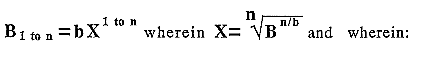
- Such self adjusting arrangement is provided by a suitably shaped cam, engaging such bridge guide with its operative contour, which is in the form of an exponential spiral, defined by the following formula:

B n = maximum weight arm (to be established experimentally);
n = number of (arbitrary) cam segments or α angle sections;
α = angle of amenability (to be established experimentally);
b; B₁; B₂; B₃;.......B n = Arms of weight;
r; R₁; R₂; R₃;.......R n = Points of weight. - A so profiled cam provide an easy and control over tiles of various thickness.
- One way of carrying out the invention is described in detail below with reference to drawings which illustrate two specific embodiments, in which:
- Figure 1 is a perspective view of device for scoring and fracturing ceramic tiles according to the present invention, of the kind comprising a scoring tool, pull operable in a direction converging towards the user. The condition of the device are with the bridge guide and consequently the driving handle completely lifted, to provide enough space thereunder to receive thickest tiles, as well as in the attitude for providing off set diagonal cuts, since a loose piece of the gauge shown in phantom lines, was removed and disposed in an appropriate receptacle, adapted also to receive the tools, such as the disk or cutter and the like.
- Figure 2 is a perspective view of device for scoring and fracturing ceramic tiles, in accordance with the present invention, of the kind comprising a scoring tool, push operable in a direction diverging from the user. The condition of the device are while a possible user is scoring a tile by one hand, while, with the other hand, operates the handles to to seize the tile which is of regular thickness The loose piece for the off set diagonal cut, was removed to show the rear parts , and particularly the wedge of steel embodied in the upper wall of the base Some section lined parts, have been broken for clearness of drawings
- Figure 3 is a detailed side view, of the user side of the device, comprising the driving handle and the fracturing arms; the driving handle, the bridge guide, the fracturing arms and the tile, are shown in different positions, distinguishable in view of the kind of the lines including them In this figure, the loose piece, to make an off set diagonal cut is applied. The attachment means are shown through a breaking.
- Figure 4 is substantially a repetition of figure 2 but partially in a reduced scale and in the attitude while the user is providing the fracturing effort after scoring.
- Figure 5 is a graph to design the curve of the cam, driven by the lever which provides either the function of first stage soft seizing, and the heavy grappling to provide fracturing The starting path includes the subdivision of the field and therefore of the curve in six segments or sections.
- Referring now to the figures of the drawings, a device for scoring and fracturing ceramic tiles comprises, conventionally, a
base 1, possibly embodying a graduatedgauge bar 1′, from which project: at least awedge 10 and arib 10′, as well as twouprights end uprights bridge guide 2, provided by twoparallel rods 2′ and 2˝, wherein atool 3, is shiftably mounted therealong, ahandle 3′, afollower 3˝, in the form of handle-bar, a substantiallyrodlike body 30, and at the bottom thereof a disk orcutter 31. Fastened to thebridge guide 2, there is a pressure means 33, provided by a pair offins 33′, 22˝. An antagonistfixed handle 4 is attached to the base in line with thebridge guide 2 and projecting outwardly, therefrom. Substantially placed above to thefixed handle 4, there is amovable handle 40, which is swingable and cooperates with thebridge guide 2. On theupper surface 14, of thebase 1, including thewedge 10 and therib 10′, are fastened by adhesive, not shown, theresilient pads base 1 and particularly from the bottom surface thereof, project three ormore shoes 16, of resilient material, having a high adherence, such as rubber or the like. - According to the present invention, on the
base 1, the graduatedgauge 1′, is provided with at leastsection 010, which is removable, as a loose piece to be spoken hereunder. Thebase 1 is made of light alloy, obtained by a casting process and in it are embedded at least awedge 10, made of very hard steel, as well as thebottom end 11′ of upright 11. - In accordance with an essential feature of the present invention,
bridge guide 2, provided by twoparallel rods 2′ and 2˝, is pivotally mounted, with itsend 20, to the upright 11, at the far end from the user, while theend 20′, adjacent to the user is urged upward by a spring 6 and may be forced downward by acam 40′, including alever 40, swingably mounted on the upright 12. Its position is such that a cam swinging covers a complete thickness range of the tiles (0, 01, 02, 03) as needed by the cutter user, i.e. frommm 4 tomm 20,.is obtained Since the resistance opposed to fracturing by the tile varies substantially with cube of thickness, thecam 40′ is shaped with aprofile 44 in the form a logarithmic spiral (figure 5). From figure 5 and in part from figure 3 it may be seen that for designing the cam operative profile, which is in the form of an exponential spiral, the following formula can be used:
B n = maximum weight arm (to be established experimentally);
n = number of (arbitrary) cam segments or α angle sections;
α = angle of amenability (to be established experimentally);
b; B₁; B₂; B₃;.......B n = Arms of weight;
r; R₁; R₂; R₃;.......R n = Points of weight. - Arguments b; Bn; are established experimentally and n is established arbitrarily, in this case as 6; α angle is split into six sections and on each of them is entered respectively, the arm, B which is analytically calculated by said formula. In consideration that the profile of cam may be 8 cm of length, the sixth root of 8
returns 1,4142.... - Now a short description of operation of the tile cutter will be given. The tile cutter is placed, generally on the floor, so that the
feet 16 adhere to the same, possibly without wasting it. In stationary condition (figure 1) thebridge guide 2 and, consequently thedriving handle 40 are completely lifted, to provide enough space thereunder to receivetiles 0 of highest thickness (figure 3), and in particular under the press arms offins 33′, 33˝ or between the same andwedge 10. At this stage, atile 0, which may be a thin one, 01, e.g. of 4 mm, as shown in phantom lines.is accommodated in such interstice. Swinging downward thehandle 40, in an anticlockwise direction, thebridge guide 2, as well as thepress arm 33′, 33˝, engaging such thin line, assume a position also indicated in phantom lines in figure 3. Withthicker tiles mm lever 40 is contained within the grasping limits of the seizer's hand acting between thehandle 40 itself and thefixed handle 4. Once the press arms engage the tile or provide such engagement, thethumb 00 of the user's hand engages, the seat orindent 040, which is rather close to its fulcrum F. Thus it operates with a relatively reduced arm providing a wanted, drastic, reduced advantage obtained with thehandle 40; this avoids anticipated heavy stress of the tiles (0, 01, 02, 03) which could accidentally break it. Whereas, such heavy stress is necessary, after scoring for fracturing the tile 02 (figure 4).and this may be obtained maximizing the power arm, i.e., engaging thehandles push scoring tool 03′ (figure 2) the latter is operated in a direction diverging, from the user, whereby to score thetile 02; this is made with one hand, while through the other hand, as aforesaid, thetile 02 is seized. The reaction of the operating pushing force, tending to displace the cutter from its proper position is counteracted in part by adherence offeet 16 over the supporting surface and in part acting with thethumb 00 within theindent 040. This management and distribution of the force to be provided is advantageous in providing a perfect scoring, even to reduce the fracturing force (figure 4). - According to a preferred embodiment of the present invention, for offset diagonal cut to accommodate the tiles (0, 01, 02, 03) to be cut, removal of a
loose piece 010 of thegauge 1′, to register the tile 0.in suitable position, is provided. - In accordance with another embodiment of the present invention the tile cutter is provided with a
receptacle 7, including alid 7′, to receive theloose piece 010, as well as disks orcutters 31′ and the like (figure 1). - In case that the cutter, as shown in figure, 1 is provided with a pull driven
tool 3 the force may be even better controlled avoiding overload on thehandle 40 which could break thetile 0.
Claims (8)
B n = maximum weight arm (to be established experimentally);
n = number of (arbitrary) cam segments or α angle sections;
α = angle of amenability (to be established experimentally);
b; B₁; B₂; B₃;.......B n = Arms of weight;
r; R₁; R₂; R₃;.......R n = Points of weight
Priority Applications (1)
| Application Number | Priority Date | Filing Date | Title |
|---|---|---|---|
| AT88111376T ATE74549T1 (en) | 1987-07-15 | 1988-07-15 | DEVICE FOR SCORING AND BREAKING CERAMIC TILES. |
Applications Claiming Priority (2)
| Application Number | Priority Date | Filing Date | Title |
|---|---|---|---|
| IT8783642A IT8783642A0 (en) | 1987-07-15 | 1987-07-15 | PROCEDURE FOR THE MANUFACTURING OF MACHINES TO ENGRAV AND CLEARLY BREAK THE VERY HARD, HOMOGENOUS CERAMIC TILES AND MACHINES OBTAINED WITH THIS PROCEDURE. |
| IT8364287 | 1987-07-15 |
Publications (2)
| Publication Number | Publication Date |
|---|---|
| EP0299501A1 true EP0299501A1 (en) | 1989-01-18 |
| EP0299501B1 EP0299501B1 (en) | 1992-04-08 |
Family
ID=11323564
Family Applications (1)
| Application Number | Title | Priority Date | Filing Date |
|---|---|---|---|
| EP88111376A Expired - Lifetime EP0299501B1 (en) | 1987-07-15 | 1988-07-15 | Device for scoring and fracturing ceramic tiles |
Country Status (5)
| Country | Link |
|---|---|
| EP (1) | EP0299501B1 (en) |
| AT (1) | ATE74549T1 (en) |
| DE (1) | DE3869858D1 (en) |
| DK (1) | DK392688A (en) |
| IT (1) | IT8783642A0 (en) |
Cited By (3)
| Publication number | Priority date | Publication date | Assignee | Title |
|---|---|---|---|---|
| US5480081A (en) * | 1993-09-24 | 1996-01-02 | Diamant Boart, Inc. | Scoring and breaking device with a carrying case therefor |
| CN103770225A (en) * | 2013-12-31 | 2014-05-07 | 佛山市永盛达机械有限公司 | Four-freedom-degree water blade slitting method and device |
| ES2633609A1 (en) * | 2016-03-21 | 2017-09-22 | Germans Boada, S.A. | Separating device applicable to ceramic manual cutters (Machine-translation by Google Translate, not legally binding) |
Families Citing this family (1)
| Publication number | Priority date | Publication date | Assignee | Title |
|---|---|---|---|---|
| DE102010009197B4 (en) | 2010-02-24 | 2012-09-20 | Gabriele Dahm-Heuckmann | Device for breaking plates and flat laying material |
Citations (4)
| Publication number | Priority date | Publication date | Assignee | Title |
|---|---|---|---|---|
| US1297539A (en) * | 1918-05-23 | 1919-03-18 | Adrian P Bull | Cam-clamp. |
| DE1652521A1 (en) * | 1966-05-30 | 1971-03-25 | Otto Thaning | Process for dismantling bodies from crystalline materials |
| GB2021036A (en) * | 1978-05-17 | 1979-11-28 | Mirco Raimondi | A Tool for cutting tiles |
| US4378782A (en) * | 1981-05-01 | 1983-04-05 | Red Devil Inc. | Ceramic tile cutter |
-
1987
- 1987-07-15 IT IT8783642A patent/IT8783642A0/en unknown
-
1988
- 1988-07-14 DK DK392688A patent/DK392688A/en not_active Application Discontinuation
- 1988-07-15 EP EP88111376A patent/EP0299501B1/en not_active Expired - Lifetime
- 1988-07-15 AT AT88111376T patent/ATE74549T1/en not_active IP Right Cessation
- 1988-07-15 DE DE8888111376T patent/DE3869858D1/en not_active Expired - Fee Related
Patent Citations (4)
| Publication number | Priority date | Publication date | Assignee | Title |
|---|---|---|---|---|
| US1297539A (en) * | 1918-05-23 | 1919-03-18 | Adrian P Bull | Cam-clamp. |
| DE1652521A1 (en) * | 1966-05-30 | 1971-03-25 | Otto Thaning | Process for dismantling bodies from crystalline materials |
| GB2021036A (en) * | 1978-05-17 | 1979-11-28 | Mirco Raimondi | A Tool for cutting tiles |
| US4378782A (en) * | 1981-05-01 | 1983-04-05 | Red Devil Inc. | Ceramic tile cutter |
Cited By (3)
| Publication number | Priority date | Publication date | Assignee | Title |
|---|---|---|---|---|
| US5480081A (en) * | 1993-09-24 | 1996-01-02 | Diamant Boart, Inc. | Scoring and breaking device with a carrying case therefor |
| CN103770225A (en) * | 2013-12-31 | 2014-05-07 | 佛山市永盛达机械有限公司 | Four-freedom-degree water blade slitting method and device |
| ES2633609A1 (en) * | 2016-03-21 | 2017-09-22 | Germans Boada, S.A. | Separating device applicable to ceramic manual cutters (Machine-translation by Google Translate, not legally binding) |
Also Published As
| Publication number | Publication date |
|---|---|
| ATE74549T1 (en) | 1992-04-15 |
| DE3869858D1 (en) | 1992-05-14 |
| DK392688D0 (en) | 1988-07-14 |
| DK392688A (en) | 1989-01-16 |
| IT8783642A0 (en) | 1987-07-15 |
| EP0299501B1 (en) | 1992-04-08 |
Similar Documents
| Publication | Publication Date | Title |
|---|---|---|
| US4401233A (en) | Dispenser for sheets of paper and the like | |
| EP0399830B1 (en) | Sheet dispenser | |
| US5165570A (en) | Sheet dispenser | |
| EP0085325B1 (en) | Tablet breaking device | |
| US20030084574A1 (en) | Tablet cutter | |
| EP1736082A1 (en) | Corn scraper | |
| EP0299501A1 (en) | Device for scoring and fracturing ceramic tiles | |
| IT1286968B1 (en) | SEMI-AUTOMATIC EQUIPMENT TO CUT THE PIZZA INTO SEVERAL PIECES OF THE SAME SIZE | |
| JP3604394B2 (en) | Knife removal tool | |
| AU742760B2 (en) | Dental casting mold device | |
| US7409764B2 (en) | Cake cutter and server | |
| AU2003262784A1 (en) | Power gear guillotine trimmer | |
| US5039054A (en) | Safe height-adjusting device | |
| US6557259B1 (en) | Uniform artificial nail clipper | |
| US6389944B1 (en) | Bagel holder | |
| US4339012A (en) | Baby scale | |
| US20090277013A1 (en) | Utensil | |
| CN210175946U (en) | Semi-automatic chopstick sorting machine | |
| US4230015A (en) | Tamborine | |
| IT1236636B (en) | HAND-ADJUSTABLE EGG SLICER WITH ONE USER HAND. | |
| GB2077176A (en) | Jaw for wire-stripping pliers | |
| WO1996012411A1 (en) | Method and device for cutting meat | |
| ES1023426U (en) | Cutting device for exfoliating slate. (Machine-translation by Google Translate, not legally binding) | |
| JP4384764B2 (en) | ruler | |
| AU2679188A (en) | A position estimating device for use in a game of bowls |
Legal Events
| Date | Code | Title | Description |
|---|---|---|---|
| PUAI | Public reference made under article 153(3) epc to a published international application that has entered the european phase |
Free format text: ORIGINAL CODE: 0009012 |
|
| AK | Designated contracting states |
Kind code of ref document: A1 Designated state(s): AT BE CH DE ES FR GB IT LI LU NL SE |
|
| 17P | Request for examination filed |
Effective date: 19890706 |
|
| 17Q | First examination report despatched |
Effective date: 19900731 |
|
| GRAA | (expected) grant |
Free format text: ORIGINAL CODE: 0009210 |
|
| AK | Designated contracting states |
Kind code of ref document: B1 Designated state(s): AT BE CH DE ES FR GB IT LI LU NL SE |
|
| PG25 | Lapsed in a contracting state [announced via postgrant information from national office to epo] |
Ref country code: SE Effective date: 19920408 Ref country code: NL Effective date: 19920408 Ref country code: LI Effective date: 19920408 Ref country code: FR Effective date: 19920408 Ref country code: ES Free format text: THE PATENT HAS BEEN ANNULLED BY A DECISION OF A NATIONAL AUTHORITY Effective date: 19920408 Ref country code: CH Effective date: 19920408 Ref country code: BE Effective date: 19920408 Ref country code: AT Effective date: 19920408 |
|
| REF | Corresponds to: |
Ref document number: 74549 Country of ref document: AT Date of ref document: 19920415 Kind code of ref document: T |
|
| REF | Corresponds to: |
Ref document number: 3869858 Country of ref document: DE Date of ref document: 19920514 |
|
| ITF | It: translation for a ep patent filed |
Owner name: UFFICIO BREVETTI VARESINO |
|
| PG25 | Lapsed in a contracting state [announced via postgrant information from national office to epo] |
Ref country code: GB Effective date: 19920715 |
|
| REG | Reference to a national code |
Ref country code: CH Ref legal event code: PL |
|
| PG25 | Lapsed in a contracting state [announced via postgrant information from national office to epo] |
Ref country code: LU Free format text: LAPSE BECAUSE OF NON-PAYMENT OF DUE FEES Effective date: 19920731 |
|
| EN | Fr: translation not filed | ||
| NLV1 | Nl: lapsed or annulled due to failure to fulfill the requirements of art. 29p and 29m of the patents act | ||
| PLBE | No opposition filed within time limit |
Free format text: ORIGINAL CODE: 0009261 |
|
| STAA | Information on the status of an ep patent application or granted ep patent |
Free format text: STATUS: NO OPPOSITION FILED WITHIN TIME LIMIT |
|
| GBPC | Gb: european patent ceased through non-payment of renewal fee |
Effective date: 19920715 |
|
| 26N | No opposition filed | ||
| PG25 | Lapsed in a contracting state [announced via postgrant information from national office to epo] |
Ref country code: DE Effective date: 19930401 |
|
| PG25 | Lapsed in a contracting state [announced via postgrant information from national office to epo] |
Ref country code: IT Free format text: LAPSE BECAUSE OF NON-PAYMENT OF DUE FEES;WARNING: LAPSES OF ITALIAN PATENTS WITH EFFECTIVE DATE BEFORE 2007 MAY HAVE OCCURRED AT ANY TIME BEFORE 2007. THE CORRECT EFFECTIVE DATE MAY BE DIFFERENT FROM THE ONE RECORDED. Effective date: 20050715 |