EP0298693A2 - Self feeding pump - Google Patents
Self feeding pump Download PDFInfo
- Publication number
- EP0298693A2 EP0298693A2 EP88306103A EP88306103A EP0298693A2 EP 0298693 A2 EP0298693 A2 EP 0298693A2 EP 88306103 A EP88306103 A EP 88306103A EP 88306103 A EP88306103 A EP 88306103A EP 0298693 A2 EP0298693 A2 EP 0298693A2
- Authority
- EP
- European Patent Office
- Prior art keywords
- suspension
- shaft
- propeller
- impeller
- pump
- Prior art date
- Legal status (The legal status is an assumption and is not a legal conclusion. Google has not performed a legal analysis and makes no representation as to the accuracy of the status listed.)
- Withdrawn
Links
Images
Classifications
-
- F—MECHANICAL ENGINEERING; LIGHTING; HEATING; WEAPONS; BLASTING
- F04—POSITIVE - DISPLACEMENT MACHINES FOR LIQUIDS; PUMPS FOR LIQUIDS OR ELASTIC FLUIDS
- F04D—NON-POSITIVE-DISPLACEMENT PUMPS
- F04D31/00—Pumping liquids and elastic fluids at the same time
-
- F—MECHANICAL ENGINEERING; LIGHTING; HEATING; WEAPONS; BLASTING
- F04—POSITIVE - DISPLACEMENT MACHINES FOR LIQUIDS; PUMPS FOR LIQUIDS OR ELASTIC FLUIDS
- F04D—NON-POSITIVE-DISPLACEMENT PUMPS
- F04D29/00—Details, component parts, or accessories
- F04D29/18—Rotors
- F04D29/22—Rotors specially for centrifugal pumps
- F04D29/2261—Rotors specially for centrifugal pumps with special measures
- F04D29/2277—Rotors specially for centrifugal pumps with special measures for increasing NPSH or dealing with liquids near boiling-point
-
- F—MECHANICAL ENGINEERING; LIGHTING; HEATING; WEAPONS; BLASTING
- F04—POSITIVE - DISPLACEMENT MACHINES FOR LIQUIDS; PUMPS FOR LIQUIDS OR ELASTIC FLUIDS
- F04D—NON-POSITIVE-DISPLACEMENT PUMPS
- F04D29/00—Details, component parts, or accessories
- F04D29/40—Casings; Connections of working fluid
- F04D29/42—Casings; Connections of working fluid for radial or helico-centrifugal pumps
- F04D29/426—Casings; Connections of working fluid for radial or helico-centrifugal pumps especially adapted for liquid pumps
- F04D29/4273—Casings; Connections of working fluid for radial or helico-centrifugal pumps especially adapted for liquid pumps suction eyes
-
- F—MECHANICAL ENGINEERING; LIGHTING; HEATING; WEAPONS; BLASTING
- F04—POSITIVE - DISPLACEMENT MACHINES FOR LIQUIDS; PUMPS FOR LIQUIDS OR ELASTIC FLUIDS
- F04D—NON-POSITIVE-DISPLACEMENT PUMPS
- F04D29/00—Details, component parts, or accessories
- F04D29/40—Casings; Connections of working fluid
- F04D29/42—Casings; Connections of working fluid for radial or helico-centrifugal pumps
- F04D29/44—Fluid-guiding means, e.g. diffusers
- F04D29/445—Fluid-guiding means, e.g. diffusers especially adapted for liquid pumps
- F04D29/448—Fluid-guiding means, e.g. diffusers especially adapted for liquid pumps bladed diffusers
Definitions
- the invention relates to a centrifugal pump and to a method of pumping medium consistency suspensions such as paper pulp. More particularly, the invention relates to such a pump which does not require a vacuum system to remove gas from the pump.
- the invention is particularly applicable to medium consistency finely comminuted cellulosic fibrous material suspensions (paper pulp) which have a consistency of between about 6-20%.
- Vacuum systems are usually not needed if the pumps are installed on the bottoms of high density towers or on the bottoms or sides of long chutes (e.g. 10 meters or greater).
- Approaches have been suggested for mechanically feeding suspension to the pump so that even where short chutes or towers or vessels are present it is not necessary to degas the suspension, see U.S. patents 4,531,892 and 4,637,779. While such approaches can be generally successful, there are practical difficulties associated therewith, and/or the equipment is unduly complicated.
- a centrifugal pump of the invention is simple in construction yet can effectively mechanically feed the pulp to the impeller so that a vacuum system is not necessary though the pump can be employed in short chutes, towers, or the like.
- the invention provides a self feeding pump 10 for pumping a suspension, the pump comprising a main housing 11 including a suspension inlet 12 and a suspension outlet 13 generally transverse to the suspension inlet; a shaft 14 rotatable about an axis A-A of rotation generally in alignment with the inlet and a fluidizing impeller 18 mounted above the shaft 14 for rotation therewith for effecting fluidization of suspension pumped by the impeller from the inlet 12 to the outlet 13 characterised in that means 24, 25 are connected to the shaft 14 for positively feeding suspension directly to the impeller blades 18 and in that no fixed or rotary blades are present between the means 24, 25 and the impeller 18.
- the self-feeding means comprises a hollow boat-type propeller 24 disposed exteriorly of the housing 11.
- the shaft 14 is preferably also hollow and includes openings 15, 16 along its length whereby gases may be separated from the suspension during operation of the pump.
- the invention provides a method of pumping a suspension having a consistency of about 6 to 20%, in the absence of a vacuum gas removal system, the method comprising passing a suspension through a centrifugal pump 10 having an impeller 18 from an inlet 12 to an outlet 13 and causing gas to separate from the suspension characterised by applying pressure to the suspension by means 24 to urge the suspension directly to the impeller blades 18 in the absence of obstructing blades.
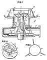
- a centrifugal pump according to the present invention is shown generally by reference numeral 10 in FIGURE 1.
- the pump comprises a main housing 11 including a suspension (e.g. pulp) inlet 12 and a suspension outlet 13 generally transverse to the inlet 12.
- a shaft 14 is mounted by bearings or the like (not shown) for rotation about axis A-A, generally in alignment with the inlet 12.
- the shaft 14 is hollow having a plurality of elongated slots 15, 16 therein, the slots 15, 16 being generally, although typically not exactly, parallel to the axis A-A, and allowing communication between the interior and the exterior of the hollow shaft l4.
- gas in the pulp will collect at shaft 14, pass through openings 15 into shaft 14, and then will pass out through slots 16 and be discharged with the pulp out through the outlet 13.
- a fluidizing impeller is associated with the rotating shaft 14.
- the impeller preferably takes the form of a plurality of impeller blades or vanes 18. These vanes have a first portion 19 thereof which is generally, although typically not exactly, parallel to the axis A-A, the vanes gradually changing direction at the central portion thereof and providing a second portion 20 thereof which is generally, although typically not exactly, perpendicular to the axis A-A.
- the shaft 14, with attached blades 18, is rotated about the axis A-A at high speed as by motor-driven shaft 21, effecting fluidization of suspension that it pumps and pumping the suspension from the housing inlet 12 to the outlet 13.
- the pump 10 includes means for positively feeding suspension to the impeller blades 18. That is the pump 10 includes means that make the pump self-feeding.
- the self-feeding means take the form of a boat-type propeller 24 which has vanes 25.
- the propeller 24 is hollow and is disposed so that the vanes 25 thereof force suspension directly to the impeller blades 18, much like the vanes of a boat propeller force the water away from the boat.
- the propeller 24 is affixed to the shaft 14, the shaft 14 and propeller 24 both typically being made of metal.
- housing 11 is open between the propeller 24 and the blades 18; that is there are no intervening elements that might retard the direct feeding of suspension from the propeller blades 25 to the impeller blades 18.
- the propeller 24 is preferably disposed with respect to the housing 11 so that it is exterior of the housing (or at least a majority thereof is exterior of the housing), at the suspension inlet 12, as illustrated in FIGURE 1.
- the propeller 24 extends into the interior of a vessel 30, such as a chute or a tower, with which the pump 10 is associated.
- the maximum diameter 26 of the propeller 24 is typically just slightly smaller than the internal diameter of the suspension inlet 12, and the diameter of the opening 31 in the bottom of the vessel 30 co-operating with the suspension inlet 12.
- anti-rotation means shown generally by reference numeral 33.
- the anti-rotation means 33 as illustrated in FIGURES 1 and 3, preferably comprise a plurality of stator vanes 34 that are disposed around the propeller 24, being welded or otherwise attached to the vessel 30.
- a ring 35 may be welded or otherwise attached to the stator vanes 34 at the top portions thereof in order to provide rigidity.
- the vanes 34 extend generally, although not necessarily exactly, parallel to the axis A-A, and they are mounted exteriorly of the propeller 24. Typically, the interiormost edges of the vanes 34 define an imaginary circle concentric with the axis A-A, and in fact of approximately the same dimensions as the inlet 12 and opening 31. The vanes may be disposed radially, as illustrated in the drawings.
- the motor-driven shaft 21 effects rotation of the shaft 14 and blades 18 and propeller 24 attached thereto, the shaft 14 being rotated at a speed (e.g. about 2500-3500 rpm) high enough so that the blades 18 effect fluidization of suspension having a consistency of between about 6-20%.
- the propeller contacts pulp within the vessel 30 and in co-operation with blades 25 feeds the pulp toward the impeller blades 18. Any pulp that is rotated too forcefully will impact the stator vanes 34 and the rotation will be terminated, so that a swirling mass does not develop in the bottom of the vessel 30.
- Once the pulp is received by the vanes 18 it is fluidised and pumped from the inlet 12 to the outlet 13.
- the propeller 24 provides sufficient action so that the pump 10 is self feeding i.e. it will operate without interruption despite the absence of a vacuum system.
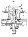
- FIGURE 4 structures identical to those in the FIGURES 1 through 3 embodiment are shown by the same reference numeral.
- FIGURE 4 embodiment provision is made for removal of the gas in the pulp through different means than the outlet 13.
- gas collecting in shaft 14 and passing through the slots 15, 16 into the hollow interior of shaft 14 will pass through one of a plurality of openings 41 in the plate 40 mounting the blades 18 and connecting the shaft 14 to the driven-shaft 21.
- the openings 41 are disposed beneath the portion of shaft 14 containing the slots 16 and may be disposed in any desired configuration, such as in a circular configuration. Fluid and gas that passes through openings 41 is acted upon by the wings 44, 45, the wings 44 in particular throwing out pulp which may pass with the gas through the openings 41, and also keeping the area around the shaft 21 clear and open.
- the gas is discharged through the opening 42 in housing 11.
- Conventional drive 46 drives the shaft 21.
- FIGURE 4 it will be seen that gas is removed separately from the suspension pumping, but without the necessity of a vacuum system. This is because the propeller 24 creates a pressure that acts on the gas that is greater than atmospheric pressure and therefore there is a tendency for the gas to be forced out of the device 10. Without the propeller 24 the apparatus of FIGURE 4 would not correctly function to separate gas from the pulp being pumped.
Landscapes
- Engineering & Computer Science (AREA)
- Mechanical Engineering (AREA)
- General Engineering & Computer Science (AREA)
- Paper (AREA)
- Structures Of Non-Positive Displacement Pumps (AREA)
Abstract
Description
- The invention relates to a centrifugal pump and to a method of pumping medium consistency suspensions such as paper pulp. More particularly, the invention relates to such a pump which does not require a vacuum system to remove gas from the pump. The invention is particularly applicable to medium consistency finely comminuted cellulosic fibrous material suspensions (paper pulp) which have a consistency of between about 6-20%.
- Many pumps for such suspensions include vacuum systems, see U.S. patents 4,435,193, 4,410,337 and 4,273,562. Vacuum systems are usually not needed if the pumps are installed on the bottoms of high density towers or on the bottoms or sides of long chutes (e.g. 10 meters or greater). Approaches have been suggested for mechanically feeding suspension to the pump so that even where short chutes or towers or vessels are present it is not necessary to degas the suspension, see U.S. patents 4,531,892 and 4,637,779. While such approaches can be generally successful, there are practical difficulties associated therewith, and/or the equipment is unduly complicated.
- According to the present invention, a centrifugal pump of the invention is simple in construction yet can effectively mechanically feed the pulp to the impeller so that a vacuum system is not necessary though the pump can be employed in short chutes, towers, or the like.
- In one aspect the invention provides a
self feeding pump 10 for pumping a suspension, the pump comprising a main housing 11 including asuspension inlet 12 and asuspension outlet 13 generally transverse to the suspension inlet; ashaft 14 rotatable about an axis A-A of rotation generally in alignment with the inlet and a fluidizingimpeller 18 mounted above theshaft 14 for rotation therewith for effecting fluidization of suspension pumped by the impeller from theinlet 12 to theoutlet 13 characterised in that means 24, 25 are connected to theshaft 14 for positively feeding suspension directly to theimpeller blades 18 and in that no fixed or rotary blades are present between themeans impeller 18. - Preferably the self-feeding means comprises a hollow boat-
type propeller 24 disposed exteriorly of the housing 11. Theshaft 14 is preferably also hollow and includesopenings centrifugal pump 10 having animpeller 18 from aninlet 12 to anoutlet 13 and causing gas to separate from the suspension characterised by applying pressure to the suspension bymeans 24 to urge the suspension directly to theimpeller blades 18 in the absence of obstructing blades. - The invention is illustrated with reference to the accompanying drawings, in which:
- FIGURE 1 is a side view, partly in cross-section and partly in elevation, of one pump according to the present invention in association with an opening in the bottom of a vessel containing suspension to be pumped;
- FIGURE 2 is a top plan view of the rotatable component of the pump of FIGURE 1, showing the configuration of the propeller and impeller vanes, and looking down from the vessel, with the anti-rotation structures in the vessel removed;
- FIGURE 3 is a top plan view of the anti-rotation means in the vessel of the structure of FIGURE 1; and
- FIGURE 4 is a view like FIGURE 1 of another embodiment of a pump according to the invention.
- A centrifugal pump according to the present invention is shown generally by
reference numeral 10 in FIGURE 1. The pump comprises a main housing 11 including a suspension (e.g. pulp)inlet 12 and asuspension outlet 13 generally transverse to theinlet 12. Ashaft 14 is mounted by bearings or the like (not shown) for rotation about axis A-A, generally in alignment with theinlet 12. Theshaft 14 is hollow having a plurality ofelongated slots slots shaft 14, pass throughopenings 15 intoshaft 14, and then will pass out throughslots 16 and be discharged with the pulp out through theoutlet 13. - A fluidizing impeller is associated with the rotating
shaft 14. The impeller preferably takes the form of a plurality of impeller blades orvanes 18. These vanes have afirst portion 19 thereof which is generally, although typically not exactly, parallel to the axis A-A, the vanes gradually changing direction at the central portion thereof and providing asecond portion 20 thereof which is generally, although typically not exactly, perpendicular to the axis A-A. Theshaft 14, with attachedblades 18, is rotated about the axis A-A at high speed as by motor-drivenshaft 21, effecting fluidization of suspension that it pumps and pumping the suspension from thehousing inlet 12 to theoutlet 13. - The
pump 10 according to the invention includes means for positively feeding suspension to theimpeller blades 18. That is thepump 10 includes means that make the pump self-feeding. In the preferred embodiment illustrated in the drawing, the self-feeding means take the form of a boat-type propeller 24 which hasvanes 25. Thepropeller 24 is hollow and is disposed so that thevanes 25 thereof force suspension directly to theimpeller blades 18, much like the vanes of a boat propeller force the water away from the boat. Thepropeller 24 is affixed to theshaft 14, theshaft 14 andpropeller 24 both typically being made of metal. - Note that the housing 11 is open between the
propeller 24 and theblades 18; that is there are no intervening elements that might retard the direct feeding of suspension from thepropeller blades 25 to theimpeller blades 18. - The
propeller 24 is preferably disposed with respect to the housing 11 so that it is exterior of the housing (or at least a majority thereof is exterior of the housing), at thesuspension inlet 12, as illustrated in FIGURE 1. Typically, thepropeller 24 extends into the interior of avessel 30, such as a chute or a tower, with which thepump 10 is associated. Themaximum diameter 26 of thepropeller 24 is typically just slightly smaller than the internal diameter of thesuspension inlet 12, and the diameter of theopening 31 in the bottom of thevessel 30 co-operating with thesuspension inlet 12. - Of course a major purpose of the
propeller 24 is to effect feeding of suspension to theimpeller blades 18. In order to facilitate that function, it is desirable, and in some cases necessary, to prevent rotation of thepropeller 24 from being merely translated into rotation of the suspension. In order to accomplish that function, anti-rotation means, shown generally byreference numeral 33, are provided. The anti-rotation means 33, as illustrated in FIGURES 1 and 3, preferably comprise a plurality ofstator vanes 34 that are disposed around thepropeller 24, being welded or otherwise attached to thevessel 30. Aring 35 may be welded or otherwise attached to thestator vanes 34 at the top portions thereof in order to provide rigidity. Thevanes 34 extend generally, although not necessarily exactly, parallel to the axis A-A, and they are mounted exteriorly of thepropeller 24. Typically, the interiormost edges of thevanes 34 define an imaginary circle concentric with the axis A-A, and in fact of approximately the same dimensions as theinlet 12 and opening 31. The vanes may be disposed radially, as illustrated in the drawings. - In a typical operation of the structure according to FIGURES 1-3 of the invention, the motor-driven
shaft 21 effects rotation of theshaft 14 andblades 18 andpropeller 24 attached thereto, theshaft 14 being rotated at a speed (e.g. about 2500-3500 rpm) high enough so that theblades 18 effect fluidization of suspension having a consistency of between about 6-20%. The propeller contacts pulp within thevessel 30 and in co-operation withblades 25 feeds the pulp toward theimpeller blades 18. Any pulp that is rotated too forcefully will impact thestator vanes 34 and the rotation will be terminated, so that a swirling mass does not develop in the bottom of thevessel 30. Once the pulp is received by thevanes 18 it is fluidised and pumped from theinlet 12 to theoutlet 13. Thepropeller 24 provides sufficient action so that thepump 10 is self feeding i.e. it will operate without interruption despite the absence of a vacuum system. - In the embodiment of FIGURE 4 structures identical to those in the FIGURES 1 through 3 embodiment are shown by the same reference numeral.
- In the FIGURE 4 embodiment, provision is made for removal of the gas in the pulp through different means than the
outlet 13. In the FIGURE 4 embodiment, gas collecting inshaft 14 and passing through theslots shaft 14 will pass through one of a plurality ofopenings 41 in theplate 40 mounting theblades 18 and connecting theshaft 14 to the driven-shaft 21. Theopenings 41 are disposed beneath the portion ofshaft 14 containing theslots 16 and may be disposed in any desired configuration, such as in a circular configuration. Fluid and gas that passes throughopenings 41 is acted upon by thewings wings 44 in particular throwing out pulp which may pass with the gas through theopenings 41, and also keeping the area around theshaft 21 clear and open. The gas is discharged through the opening 42 in housing 11.Conventional drive 46 drives theshaft 21. - In the embodiment of FIGURE 4, it will be seen that gas is removed separately from the suspension pumping, but without the necessity of a vacuum system. This is because the
propeller 24 creates a pressure that acts on the gas that is greater than atmospheric pressure and therefore there is a tendency for the gas to be forced out of thedevice 10. Without thepropeller 24 the apparatus of FIGURE 4 would not correctly function to separate gas from the pulp being pumped. - Thus, it will be seen that according to the present invention a simple and effective apparatus is provided for centrifugal pumping of medium consistency slurries even from short chutes or towers or like vessels, without the necessity of a vacuum gas removal system; and an associated simplified method for effecting pumping.
Claims (11)
Applications Claiming Priority (2)
| Application Number | Priority Date | Filing Date | Title |
|---|---|---|---|
| US07/070,058 US4826398A (en) | 1987-07-06 | 1987-07-06 | Medium consistency pump with self-feeding |
| US70058 | 1987-07-06 |
Publications (2)
| Publication Number | Publication Date |
|---|---|
| EP0298693A2 true EP0298693A2 (en) | 1989-01-11 |
| EP0298693A3 EP0298693A3 (en) | 1990-07-18 |
Family
ID=22092857
Family Applications (1)
| Application Number | Title | Priority Date | Filing Date |
|---|---|---|---|
| EP88306103A Withdrawn EP0298693A3 (en) | 1987-07-06 | 1988-07-05 | Self feeding pump |
Country Status (8)
| Country | Link |
|---|---|
| US (1) | US4826398A (en) |
| EP (1) | EP0298693A3 (en) |
| JP (1) | JPS6477789A (en) |
| BR (1) | BR8803343A (en) |
| CA (1) | CA1315600C (en) |
| FI (1) | FI882940A7 (en) |
| NO (1) | NO170168C (en) |
| SE (1) | SE466711B (en) |
Cited By (10)
| Publication number | Priority date | Publication date | Assignee | Title |
|---|---|---|---|---|
| EP0600821A1 (en) * | 1992-12-04 | 1994-06-08 | Etablissements F. Moret (S.A.) | Use of a multi-stage propellor pump for pumping fibrous suspension concentrates and propellor pump specially adapted for this operation |
| EP0600820A1 (en) * | 1992-12-04 | 1994-06-08 | Etablissements F. Moret (S.A.) | Pump, especially for concentrated fibrous suspensions |
| CN1093606C (en) * | 1996-10-11 | 2002-10-30 | 株式会社不二工机 | Drainage pump |
| AT505062B1 (en) * | 2007-03-27 | 2009-08-15 | Andritz Ag Maschf | METHOD AND DEVICE FOR PUMPING GAS-CONTAINING SUSPENSIONS, ESPECIALLY FIBER-SUSPENSIONS |
| CN101550661B (en) * | 2009-05-06 | 2011-06-15 | 江苏华机环保设备有限公司 | Impeller-type paper pulp sparger at bottom of upward flow bleaching tower |
| FR2961272A1 (en) * | 2010-06-10 | 2011-12-16 | Sarl Lequien | Pump for filling or draining out liquid manure from liquid manure tank of container in agricultural field, has suction rotor provided with conical envelope and sucking contents toward periphery of transfer rotor |
| CN102619779A (en) * | 2012-04-01 | 2012-08-01 | 江苏大学 | Turbulence generator for medium-consistency paper pulp pump |
| GB2503023A (en) * | 2012-06-14 | 2013-12-18 | Corac Energy Technologies Ltd | Compressor with separator |
| US9879692B2 (en) | 2012-03-29 | 2018-01-30 | Weir Minerals Europe Limited | Froth pump and method |
| EP4015825A1 (en) | 2020-12-21 | 2022-06-22 | Sulzer Management AG | Centrifugal pump for pumping a multiphase suspension and a gas removal device for use in a centrifugal pump |
Families Citing this family (27)
| Publication number | Priority date | Publication date | Assignee | Title |
|---|---|---|---|---|
| FI86333C (en) * | 1988-04-11 | 1992-07-10 | Ahlstroem Oy | FOERFARANDE OCH ANORDNING FOER SEPARERING AV GAS MED PUMPEN UR MEDIET SOM SKALL PUMPAS. |
| FI85751B (en) * | 1988-06-17 | 1992-02-14 | Ahlstroem Oy | FOERFARANDE OCH ANORDNING FOER PUMPNING AV TJOCKT MEDIUM. |
| GB8821729D0 (en) * | 1988-09-16 | 1988-11-16 | Nat Nuclear Corp Ltd | Impeller pumps |
| US5209641A (en) * | 1989-03-29 | 1993-05-11 | Kamyr Ab | Apparatus for fluidizing, degassing and pumping a suspension of fibrous cellulose material |
| FI89516B (en) * | 1989-05-10 | 1993-06-30 | Ahlstroem Oy | Foerfarande Foer blekning av cellulosamassa med Otson |
| US4976586A (en) * | 1989-07-18 | 1990-12-11 | Kamyr Ab | Pump with separate fluidizing vaned shaft adjacent impeller |
| US4936744A (en) * | 1989-07-25 | 1990-06-26 | Goulds Pumps, Incorporated | Centrifugal pump |
| JPH03111697A (en) * | 1989-09-22 | 1991-05-13 | Jidosha Denki Kogyo Co Ltd | Small centrifugal pump |
| US5116198A (en) * | 1990-09-07 | 1992-05-26 | Ahlstrom Corporation | Centrifugal pumping apparatus |
| FI97024C (en) * | 1991-07-15 | 1996-10-10 | Ahlstroem Oy | Method and apparatus for separating gas from a gas-containing material |
| US5302082A (en) * | 1992-07-09 | 1994-04-12 | Arde, Inc. | Improved efficiency grinding pump for slurry |
| US5413460A (en) * | 1993-06-17 | 1995-05-09 | Goulds Pumps, Incorporated | Centrifugal pump for pumping fiber suspensions |
| DE69511217T2 (en) * | 1994-11-25 | 1999-11-25 | Fujikoki Mfg. Co. Ltd., Tokio/Tokyo | Drain pump |
| GB9612201D0 (en) | 1996-06-11 | 1996-08-14 | Sweepax International Limited | Rotodynamic pump |
| FR2782755B1 (en) * | 1998-09-02 | 2000-09-29 | Inst Francais Du Petrole | POLYPHASTIC TURMOMACHINE WITH IMPROVED PHASE MIXTURE AND ASSOCIATED METHOD |
| FI111023B (en) † | 1998-12-30 | 2003-05-15 | Sulzer Pumpen Ag | Method and apparatus for pumping material and rotor used in connection with the apparatus |
| US6139379A (en) * | 1999-09-04 | 2000-10-31 | Jamieson; John R. | Jet propelled watercraft and a simplified low cost drive therefor |
| ITVI20020048A1 (en) * | 2002-03-19 | 2003-09-19 | Comer Spa | PROPULSOR FOR THE STIRRING OF SUSPENSIONS OF SOLIDS INSIDE A TREATMENT TANK |
| FI20050733A7 (en) * | 2005-06-22 | 2006-12-23 | Sulzer Pumpen Ag | Gas separation device, its front wall and separation wheel |
| DK2427632T3 (en) * | 2009-05-06 | 2017-04-03 | Curtiss-Wright Electro-Mechanical Corp | Gas-resistant underwater pump |
| CN104235061B (en) * | 2013-06-05 | 2015-06-10 | 宁波方太厨具有限公司 | Open type water pump |
| CN104235060A (en) * | 2013-06-05 | 2014-12-24 | 宁波方太厨具有限公司 | Impeller of open type water pump |
| CN106194760B (en) * | 2016-07-14 | 2019-03-29 | 西华大学 | A kind of gas-liquid separation delivery pump |
| EP3366926B1 (en) * | 2017-02-22 | 2020-12-02 | Borgwarner Inc. | Compressor impeller with curved ribs on the back side of the backplate |
| CN112555200A (en) * | 2020-11-20 | 2021-03-26 | 西安理工大学 | Multistage gas-liquid mixed transportation pump suitable for high gas content |
| CN114307259B (en) * | 2021-12-30 | 2023-05-30 | 中国航空工业集团公司金城南京机电液压工程研究中心 | Pump type oil-gas separator of hydraulic combined transmission generator |
| US12196227B2 (en) | 2022-02-04 | 2025-01-14 | Spike Brewing LLC | Pump |
Family Cites Families (16)
| Publication number | Priority date | Publication date | Assignee | Title |
|---|---|---|---|---|
| GB268572A (en) * | 1926-05-21 | 1927-04-07 | Pulsometer Eng Co | Improvements in or relating to centrifugal pumps |
| US2483335A (en) * | 1947-06-30 | 1949-09-27 | Jessie A Davis Foundation Inc | Pump |
| FR1123502A (en) * | 1954-05-06 | 1956-09-24 | Centrifugal pump with vertical shaft immersed in the liquid to be lifted | |
| DE1926074U (en) * | 1965-02-08 | 1965-10-28 | Adolf Baehrs | MOTOR-DRIVEN JAUCHE DENSITY PUMP. |
| CH495293A (en) * | 1969-05-19 | 1970-08-31 | Kaelin J R | Vertical axis aerator for aerating liquids |
| US3945761A (en) * | 1971-09-02 | 1976-03-23 | Toshinobu Araoka | Fan disturbing sand at the bottom of a body of water so that it may be pumped up efficiently |
| US4273562A (en) * | 1979-10-01 | 1981-06-16 | A. Ahlstrom Osakeyhtio | Method and apparatus for pumping gaseous liquids and separating the gaseous components therefrom |
| US4435193A (en) * | 1980-04-07 | 1984-03-06 | Kamyr Ab | Controlling operation of a centrifugal pump |
| US4410337A (en) * | 1980-04-07 | 1983-10-18 | A. Ahlstrom Osakeyhtio | Method and an apparatus for separating a gas from a fibre suspension |
| SU926372A1 (en) * | 1980-06-02 | 1982-05-07 | Предприятие П/Я М-5356 | Centrifugal pump |
| DE3372396D1 (en) * | 1982-10-28 | 1987-08-13 | Goodwin R Int Ltd | Agitating particulate solids |
| SE435951B (en) * | 1983-03-14 | 1984-10-29 | Sunds Defibrator | CENTRIFUGAL PUMP WITH SCREW FEED FOR PUMPING PUMP WITH HIGH CONCENTRATION |
| FI67580C (en) * | 1983-07-12 | 1985-04-10 | Ahlstroem Oy | FOERFARANDE OCH ANORDNING FOER FIBRERING SILNING OCH PUMPNING AV CELLULOSAMASSA OCH RETURPAPPER |
| SE452345B (en) * | 1984-04-02 | 1987-11-23 | Kamyr Ab | DEVICE FOR THE DISTRIBUTION OF SUSPENSION BY ITS INCORPORATION IN TREATMENT |
| FI73023C (en) * | 1984-07-17 | 1987-08-10 | Ahlstroem Oy | Apparatus for separating gas from a fiber suspension. |
| US4637779A (en) * | 1985-05-17 | 1987-01-20 | Kamyr, Inc. | Two stage medium consistency pulp pumping |
-
1987
- 1987-07-06 US US07/070,058 patent/US4826398A/en not_active Expired - Lifetime
-
1988
- 1988-06-20 FI FI882940A patent/FI882940A7/en not_active IP Right Cessation
- 1988-06-23 SE SE8802371A patent/SE466711B/en not_active IP Right Cessation
- 1988-06-27 CA CA000570481A patent/CA1315600C/en not_active Expired - Fee Related
- 1988-07-01 JP JP63165797A patent/JPS6477789A/en active Pending
- 1988-07-05 BR BR8803343A patent/BR8803343A/en not_active IP Right Cessation
- 1988-07-05 EP EP88306103A patent/EP0298693A3/en not_active Withdrawn
- 1988-07-05 NO NO882991A patent/NO170168C/en unknown
Cited By (13)
| Publication number | Priority date | Publication date | Assignee | Title |
|---|---|---|---|---|
| EP0600821A1 (en) * | 1992-12-04 | 1994-06-08 | Etablissements F. Moret (S.A.) | Use of a multi-stage propellor pump for pumping fibrous suspension concentrates and propellor pump specially adapted for this operation |
| EP0600820A1 (en) * | 1992-12-04 | 1994-06-08 | Etablissements F. Moret (S.A.) | Pump, especially for concentrated fibrous suspensions |
| FR2698916A1 (en) * | 1992-12-04 | 1994-06-10 | Moret Ets F | Advanced pump especially for concentrated fibrous suspensions. |
| FR2698918A1 (en) * | 1992-12-04 | 1994-06-10 | Moret Ets F | Use of a multistage propeller pump for pumping concentrated fibrous suspensions and a propeller pump specially adapted for this use. |
| CN1093606C (en) * | 1996-10-11 | 2002-10-30 | 株式会社不二工机 | Drainage pump |
| AT505062B1 (en) * | 2007-03-27 | 2009-08-15 | Andritz Ag Maschf | METHOD AND DEVICE FOR PUMPING GAS-CONTAINING SUSPENSIONS, ESPECIALLY FIBER-SUSPENSIONS |
| CN101550661B (en) * | 2009-05-06 | 2011-06-15 | 江苏华机环保设备有限公司 | Impeller-type paper pulp sparger at bottom of upward flow bleaching tower |
| FR2961272A1 (en) * | 2010-06-10 | 2011-12-16 | Sarl Lequien | Pump for filling or draining out liquid manure from liquid manure tank of container in agricultural field, has suction rotor provided with conical envelope and sucking contents toward periphery of transfer rotor |
| US9879692B2 (en) | 2012-03-29 | 2018-01-30 | Weir Minerals Europe Limited | Froth pump and method |
| CN102619779A (en) * | 2012-04-01 | 2012-08-01 | 江苏大学 | Turbulence generator for medium-consistency paper pulp pump |
| GB2503023A (en) * | 2012-06-14 | 2013-12-18 | Corac Energy Technologies Ltd | Compressor with separator |
| EP4015825A1 (en) | 2020-12-21 | 2022-06-22 | Sulzer Management AG | Centrifugal pump for pumping a multiphase suspension and a gas removal device for use in a centrifugal pump |
| WO2022135775A1 (en) | 2020-12-21 | 2022-06-30 | Sulzer Management Ag | Centrifugal pump for pumping a multiphase suspension and a gas removal device for use in a centrifugal pump |
Also Published As
| Publication number | Publication date |
|---|---|
| JPS6477789A (en) | 1989-03-23 |
| SE8802371D0 (en) | 1988-06-23 |
| CA1315600C (en) | 1993-04-06 |
| EP0298693A3 (en) | 1990-07-18 |
| NO882991D0 (en) | 1988-07-05 |
| FI882940A0 (en) | 1988-06-20 |
| NO882991L (en) | 1989-01-09 |
| SE466711B (en) | 1992-03-23 |
| FI882940A7 (en) | 1989-01-07 |
| US4826398A (en) | 1989-05-02 |
| SE8802371L (en) | 1989-01-07 |
| NO170168C (en) | 1992-09-16 |
| NO170168B (en) | 1992-06-09 |
| BR8803343A (en) | 1989-01-17 |
Similar Documents
| Publication | Publication Date | Title |
|---|---|---|
| EP0298693A2 (en) | Self feeding pump | |
| US4776758A (en) | Combined fluidizing and vacuum pump | |
| US4981413A (en) | Pump for and method of separating gas from a fluid to be pumped | |
| US5266160A (en) | Method of an apparatus for treating pulp | |
| US4637779A (en) | Two stage medium consistency pulp pumping | |
| RU2008527C1 (en) | Centrifugal pump impeller | |
| GB2048704A (en) | Rotary pulp screening device | |
| US6438864B1 (en) | Centrifugal pellet dryer apparatus | |
| FI79151C (en) | Dispensing device with sweep openings and discharge procedure e. | |
| US4744722A (en) | Method and apparatus for the mixing of liquid or gas into pulp stock | |
| JPS61502662A (en) | Device for separating gas from a suspension of fibers | |
| EP0409456B1 (en) | Pump with separate fluidizing vaned shaft adjacent impeller | |
| JPH0753955B2 (en) | Gas discharge device | |
| US4737274A (en) | Tramp material separator | |
| US5078859A (en) | Stock screening apparatus | |
| US5413460A (en) | Centrifugal pump for pumping fiber suspensions | |
| US4867845A (en) | Vertical steaming vessel | |
| US4045145A (en) | Pitot pump with turbulence elimination | |
| EP0145365A2 (en) | Rotary pulp screen of the vertical pressure type having pulp stock feed at different axial positions on the screen | |
| WO1990015183A1 (en) | Method of and apparatus for separating heavy impurities from fiber suspensions in connection with pumping | |
| US5762760A (en) | Reactor for treating pulp with a gas | |
| SU1761260A1 (en) | Sheller | |
| US20040040684A1 (en) | Arrangement for feeding pulp to a bleaching tower | |
| NO145665B (en) | PRESSURE FOR CELLULOSE AND TREMASS. | |
| WO1993011359A1 (en) | Pump with built-in vacuum pump |
Legal Events
| Date | Code | Title | Description |
|---|---|---|---|
| PUAI | Public reference made under article 153(3) epc to a published international application that has entered the european phase |
Free format text: ORIGINAL CODE: 0009012 |
|
| AK | Designated contracting states |
Kind code of ref document: A2 Designated state(s): AT BE CH DE ES FR GB GR IT LI LU NL SE |
|
| RBV | Designated contracting states (corrected) |
Designated state(s): AT DE FR |
|
| PUAL | Search report despatched |
Free format text: ORIGINAL CODE: 0009013 |
|
| AK | Designated contracting states |
Kind code of ref document: A3 Designated state(s): AT DE FR |
|
| 17P | Request for examination filed |
Effective date: 19901010 |
|
| 17Q | First examination report despatched |
Effective date: 19911206 |
|
| RAP1 | Party data changed (applicant data changed or rights of an application transferred) |
Owner name: KVAERNER PULPING TECHNOLOGIES AB |
|
| STAA | Information on the status of an ep patent application or granted ep patent |
Free format text: STATUS: THE APPLICATION HAS BEEN WITHDRAWN |
|
| 18W | Application withdrawn |
Withdrawal date: 19950505 |