EP0297609B1 - Hub setting device - Google Patents
Hub setting device Download PDFInfo
- Publication number
- EP0297609B1 EP0297609B1 EP88110573A EP88110573A EP0297609B1 EP 0297609 B1 EP0297609 B1 EP 0297609B1 EP 88110573 A EP88110573 A EP 88110573A EP 88110573 A EP88110573 A EP 88110573A EP 0297609 B1 EP0297609 B1 EP 0297609B1
- Authority
- EP
- European Patent Office
- Prior art keywords
- hub
- ring
- setting device
- circumferential surface
- divided ring
- Prior art date
- Legal status (The legal status is an assumption and is not a legal conclusion. Google has not performed a legal analysis and makes no representation as to the accuracy of the status listed.)
- Expired - Lifetime
Links
- 230000014759 maintenance of location Effects 0.000 claims description 13
- 230000000717 retained effect Effects 0.000 claims description 7
- 238000007747 plating Methods 0.000 claims description 2
- XUIMIQQOPSSXEZ-UHFFFAOYSA-N Silicon Chemical compound [Si] XUIMIQQOPSSXEZ-UHFFFAOYSA-N 0.000 description 3
- 238000003780 insertion Methods 0.000 description 3
- 230000037431 insertion Effects 0.000 description 3
- 229910052710 silicon Inorganic materials 0.000 description 3
- 239000010703 silicon Substances 0.000 description 3
- 238000004804 winding Methods 0.000 description 3
- 229920000459 Nitrile rubber Polymers 0.000 description 2
- 238000005299 abrasion Methods 0.000 description 2
- 239000000463 material Substances 0.000 description 2
- XAGFODPZIPBFFR-UHFFFAOYSA-N aluminium Chemical compound [Al] XAGFODPZIPBFFR-UHFFFAOYSA-N 0.000 description 1
- 229910052782 aluminium Inorganic materials 0.000 description 1
- 238000004140 cleaning Methods 0.000 description 1
- 230000006866 deterioration Effects 0.000 description 1
- 238000004519 manufacturing process Methods 0.000 description 1
- 229920000642 polymer Polymers 0.000 description 1
- 238000003825 pressing Methods 0.000 description 1
- 230000003252 repetitive effect Effects 0.000 description 1
Images


Classifications
-
- B—PERFORMING OPERATIONS; TRANSPORTING
- B65—CONVEYING; PACKING; STORING; HANDLING THIN OR FILAMENTARY MATERIAL
- B65H—HANDLING THIN OR FILAMENTARY MATERIAL, e.g. SHEETS, WEBS, CABLES
- B65H75/00—Storing webs, tapes, or filamentary material, e.g. on reels
- B65H75/02—Cores, formers, supports, or holders for coiled, wound, or folded material, e.g. reels, spindles, bobbins, cop tubes, cans, mandrels or chucks
- B65H75/18—Constructional details
- B65H75/24—Constructional details adjustable in configuration, e.g. expansible
- B65H75/242—Expansible spindles, mandrels or chucks, e.g. for securing or releasing cores, holders or packages
- B65H75/245—Expansible spindles, mandrels or chucks, e.g. for securing or releasing cores, holders or packages by deformation of an elastic or flexible material
-
- G—PHYSICS
- G11—INFORMATION STORAGE
- G11B—INFORMATION STORAGE BASED ON RELATIVE MOVEMENT BETWEEN RECORD CARRIER AND TRANSDUCER
- G11B15/00—Driving, starting or stopping record carriers of filamentary or web form; Driving both such record carriers and heads; Guiding such record carriers or containers therefor; Control thereof; Control of operating function
- G11B15/60—Guiding record carrier
- G11B15/66—Threading; Loading; Automatic self-loading
- G11B15/662—Positioning or locking of spool or reel
-
- G—PHYSICS
- G11—INFORMATION STORAGE
- G11B—INFORMATION STORAGE BASED ON RELATIVE MOVEMENT BETWEEN RECORD CARRIER AND TRANSDUCER
- G11B23/00—Record carriers not specific to the method of recording or reproducing; Accessories, e.g. containers, specially adapted for co-operation with the recording or reproducing apparatus ; Intermediate mediums; Apparatus or processes specially adapted for their manufacture
- G11B23/02—Containers; Storing means both adapted to cooperate with the recording or reproducing means
- G11B23/113—Apparatus or processes specially adapted for the manufacture of magazines or cassettes, e.g. initial loading into container
-
- B—PERFORMING OPERATIONS; TRANSPORTING
- B65—CONVEYING; PACKING; STORING; HANDLING THIN OR FILAMENTARY MATERIAL
- B65H—HANDLING THIN OR FILAMENTARY MATERIAL, e.g. SHEETS, WEBS, CABLES
- B65H2301/00—Handling processes for sheets or webs
- B65H2301/50—Auxiliary process performed during handling process
- B65H2301/51—Modifying a characteristic of handled material
- B65H2301/513—Modifying electric properties
- B65H2301/5133—Removing electrostatic charge
-
- B—PERFORMING OPERATIONS; TRANSPORTING
- B65—CONVEYING; PACKING; STORING; HANDLING THIN OR FILAMENTARY MATERIAL
- B65H—HANDLING THIN OR FILAMENTARY MATERIAL, e.g. SHEETS, WEBS, CABLES
- B65H2701/00—Handled material; Storage means
- B65H2701/50—Storage means for webs, tapes, or filamentary material
- B65H2701/51—Cores or reels characterised by the material
- B65H2701/514—Elastic elements
Definitions
- the present invention generally relates to an apparatus for producing a magnetic tape, and more particularly relates to a device for setting a hub for taking up thereon a magnetic tape which is cut in a predetermined tape width from an original roll of wide magnetic tape.
- magnetic tape has been widely used as a magnetic recording medium in various fields as the performance of magnetic tape has been improved.
- magnetic tape is manufactured by first producing an original roll of tape which is much wider than the rolls of tape to be actualy sold.
- the original roll of magnetic tape is then cut into tapes of a predetermined width in a slitting step.
- a magnetic tape To is cut into a plurality of magnetic tapes T n with a cutter 20, and the cut tapes are wound at a high speed onto hubs 8, which are provided in a number corresponding to the number of cut tapes.
- the cut tapes T n are subjected to further processing such as finishing at the tape edges (cut surfaces), cleaning at the front and rear surfaces, and the like.
- Each of the hubs 8 onto which the magnetic tapes T n are to be wound are removably attached to a boss member 14 of a rotary shaft 7. It is very important, in view of productivity, to make it possible to easily attach/remove the hub 8 onto/from the boss member 14 before the start and after the completion of the slitting step, and it is also very important, in view of maintaining the tape in good condition, to make it possible to surely attach the hub 8 onto the boss member 14 in such a manner that the hub has no play on the boss member. To this end, there have been proposed various devices.
- Fig. 2 shows the basic structure of a conventional hub setting device.
- the hub 8 is fitted on the boss member 14 suitably fixed on the rotary shaft 7.
- Two grooves are circumferentially formed in an outer circumferential surface 16 of the boss member 14, and in the respective grooves, O-rings 17 made of, for example, NBR (acrylonitrile-butadiene rubber) and coil springs 18 are provided, the O-rings 17 covering the upper portions of the respective O-rings 17.
- the coil springs 18 are arranged so as to suitably project from the outer circumferential surface 16 of the boss member 14.
- the hub 8 is inserted onto the thus-arranged boss member 14 in such a manner that an inner circumferential surface 9 of the hub 8 comes into contact with the coil springs 18 and the O-rings 17 and the coil springs 18 are suitably deformed while being rotated corresponding to the direction of hub insertion (the direction shown by an arrow A) as shown in Fig. 3.
- the thus-inserted hub 8 is retained due to abutment between the coil springs 18 and the inner circumferential surface 9 (mainly due to the abutment caused by the elasticity of the O-rings 17).
- each coil spring 18 can be rotated easily, while from a viewpoint of hub retention, the clearance t i is not desirable because the clearance allows play of the hub 8 on the boss member, causing deviations in the rotation of the hub, and thereby causing the attitude of the wound tape to be poor or causing microscopic chipping of the hub due to the friction between the inner circumferential surface 9 and the coil springs 18.
- the winding attitude of the magnetic tape T n wound on the hub 8 is poor, not only is the appearance of the tape not good, but the movement of the tape may be poor in a post-winding step such as a rewinding step in which the magnetic tape T n is wound onto the reel of a magnetic tape cassette, resulting in undesirable tape condition, for example, damage to the cut edges the tape.
- a post-winding step such as a rewinding step in which the magnetic tape T n is wound onto the reel of a magnetic tape cassette, resulting in undesirable tape condition, for example, damage to the cut edges the tape.
- chips of the hub material adhere to the magnetic tape Tn, thus significantly lowering the tape quality.
- boss member structures other than that shown in Fig. 2 have been proposed. However, they are substantially the same as that shown in Fig. 2, and the above problems have not been eliminated yet.
- the present invention has been attained in view of the above-mentioned various problems, and it is an object of the present invention to provide a hub setting device in which a hub can be attached/removed easily to make the productivity of the tape manufacturing process good, and with which the hub can be surely retained so that the tape quality is not lowered.
- a device for setting a hub around which a magnetic tape is to be wound as defined in appended claim 1.
- the hub setting device is provided with a boss member which engages with an inner circumferential surface of the hub so as to transmit the driving force of a rotary shaft to the hub, in which a recess portion is formed in an outer circumferential surface of the boss member and a divided ring is retained in the recess portion and urged toward the hub by elastic members so that an outer surface of the divided ring and an inner surface of the hub are in face-to-face contact with each other.
- Fig. 4 is a perspective view of a hub setting device constructed according to the present invention
- Fig. 5 is a cross section taken on a line V-V in Fig. 4.
- a boss member 1 shown in Figs. 4 and 5 is arranged to suitably engage a rotary shaft 7 so as to rotate similarly to the conventional boss member 14.
- a recess portion 3 is circumferentially formed in the center of the outer circumferential surface of the boss member 1, with a width of, for example, about one-third that of the boss member 1.
- Elastic members 4 are provided under positional restriction in receiving grooves 3a formed at the right and left ends of the recess portion 3.
- a divided ring 10 is provided over the elastic members 4, and a retention member 5 is provided around the outer circumference of the divided ring 10 so as to prevent the divided ring 10 from coming out of the recess portion 3.
- the divided ring 10 has a plate-like shape with an arcuate engagement surface 12 which comes into face-to-face contact with an inner circumferential surface 9 of the hub 8.
- the divided ring 10 is restricted in movement in the direction of the ring's width by the side surfaces of the recess portion 3.
- the divided ring 10 is arranged so as to make a circuit around the circumference of the recess portion 3, with the divided ring 10 being divided into four parts.
- a groove 11 is formed in the engagement surface 12 of the divided ring 10 at its longitudinally central portion so as to receive the retention member 5 therein.
- Ring edge portions 13 of the retention ring 5 in the longitudinally opposite ends thereof are formed as curved surfaces with a suitable curvature.
- the material of the divided ring 10 is not specifically limited, the divided ring 10 may be made of, for example, aluminum or the like, and it may be subjected to processing such as hard plating or the like so as to prevent the ring from being scratched.
- hollow tubular members for example, silicon tubes SR-No. 1 produced by Shinetsu Polymer Co., Ltd.
- the silicon tubes need not always be endless O-rings. Having a hollow structure, the silicon tubes are superior in their quantity of deformation and in elasticity, and hence in their action of urging the divided ring 10 outward from the boss member.
- the retention member 5 is not specifically limited and other devices, for example, a coil spring, an O-ring, or the like may be used so long as it has suitable elasticity.
- the retention member 5 is provided in a state where it is completely received in the groove 11, that is, it should not project out of the engagement surface 12 of the divided ring 10. It is preferable that the urging force of the retention member 5 pressing against the divided ring 10 not be too strong to prevent the latter from being suitably moved in the radial direction of the boss member 1 by the elasticity of the elastic member 4.
- the mounted hub 8 is very surely retained on the boss member 1, the accurate rotation of the hub 8 is ensured, and deviations in rotation are prevented because the engagement surface 12 of the divided ring 10, which is recessed outward from the boss member by the elastic members 4, engages the inner circumferential surface 9 over a wide engagement area and the position of the divided ring 10 is surely restricted in the recess portion 3 with no play.
- the present invention is not limited to the embodiment described above, and may be modified in various ways, for example, in the shape and number of divided rings 10, in the shape of the recess portion 3, in the use of other elastic members, etc.
- the hub setting device is arranged so that the plate-like divided ring member acting elastically in the radial direction of the boss member and accurately restricted in position in the outer circumferential surface of the boss member is in contact over a wide area with the inner circumferential surface of the hub around which magnetic tape is to be wound.
- the hub is therefore surely retained without play, and deviations in the rotational movement of the hub are suppressed, making it possible to carry out winding of the tape with accurately registered tape edges.
- the circumferential edge portions of the divided ring are formed as curved surfaces, and at least portions of the divided ring which contact the hub are hard- plated so that the hub insertion property is improved and the abrasion of the hub retaining surface (engagement surface) is prevented, thereby suppressing the generation of chips and ensuring good retention of the hub over long periods.
Landscapes
- Storage Of Web-Like Or Filamentary Materials (AREA)
- Winding Of Webs (AREA)
- Holding Or Fastening Of Disk On Rotational Shaft (AREA)
Description
- The present invention generally relates to an apparatus for producing a magnetic tape, and more particularly relates to a device for setting a hub for taking up thereon a magnetic tape which is cut in a predetermined tape width from an original roll of wide magnetic tape.
- Recently, magnetic tape has been widely used as a magnetic recording medium in various fields as the performance of magnetic tape has been improved.
- Generally, magnetic tape is manufactured by first producing an original roll of tape which is much wider than the rolls of tape to be actualy sold. The original roll of magnetic tape is then cut into tapes of a predetermined width in a slitting step. In the slitting step, as shown in Fig. 1, a magnetic tape To is cut into a plurality of magnetic tapes Tn with a
cutter 20, and the cut tapes are wound at a high speed ontohubs 8, which are provided in a number corresponding to the number of cut tapes. Although not illustrated in Fig. 3, generally, the cut tapes Tn are subjected to further processing such as finishing at the tape edges (cut surfaces), cleaning at the front and rear surfaces, and the like. - Each of the
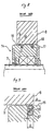
hubs 8 onto which the magnetic tapes Tn are to be wound are removably attached to aboss member 14 of arotary shaft 7. It is very important, in view of productivity, to make it possible to easily attach/remove thehub 8 onto/from theboss member 14 before the start and after the completion of the slitting step, and it is also very important, in view of maintaining the tape in good condition, to make it possible to surely attach thehub 8 onto theboss member 14 in such a manner that the hub has no play on the boss member. To this end, there have been proposed various devices. - Fig. 2 shows the basic structure of a conventional hub setting device. As shown in Fig. 2, the
hub 8 is fitted on theboss member 14 suitably fixed on therotary shaft 7. Two grooves are circumferentially formed in an outercircumferential surface 16 of theboss member 14, and in the respective grooves, O-rings 17 made of, for example, NBR (acrylonitrile-butadiene rubber) andcoil springs 18 are provided, the O-rings 17 covering the upper portions of the respective O-rings 17. Thecoil springs 18 are arranged so as to suitably project from the outercircumferential surface 16 of theboss member 14. - The
hub 8 is inserted onto the thus-arrangedboss member 14 in such a manner that an inner circumferential surface 9 of thehub 8 comes into contact with thecoil springs 18 and the O-rings 17 and thecoil springs 18 are suitably deformed while being rotated corresponding to the direction of hub insertion (the direction shown by an arrow A) as shown in Fig. 3. The thus-insertedhub 8 is retained due to abutment between thecoil springs 18 and the inner circumferential surface 9 (mainly due to the abutment caused by the elasticity of the O-rings 17). - However, because the O-
rings 17 and thecoil springs 18 have considerable variations in diameter and the hub is in line contact (strictly, point contact) with thecoil springs 18, the hub cannot be retained securely unless thecoil springs 18 are urged against the inner circumferential surface 9 with a considerably large force. However, if this force is too large, thecoil springs 18 can easily be worn by the repetitive attachment/removal of the hub. It is therefore difficult to ensure stable retention of the hub over long periods. Further, from a viewpoint of hub insertion, it is desirable to provide a suitable clearance ti relative to thegroove width 1, so that eachcoil spring 18 can be rotated easily, while from a viewpoint of hub retention, the clearance ti is not desirable because the clearance allows play of thehub 8 on the boss member, causing deviations in the rotation of the hub, and thereby causing the attitude of the wound tape to be poor or causing microscopic chipping of the hub due to the friction between the inner circumferential surface 9 and thecoil springs 18. - If the winding attitude of the magnetic tape Tn wound on the
hub 8 is poor, not only is the appearance of the tape not good, but the movement of the tape may be poor in a post-winding step such as a rewinding step in which the magnetic tape Tn is wound onto the reel of a magnetic tape cassette, resulting in undesirable tape condition, for example, damage to the cut edges the tape. There is a further problem that chips of the hub material adhere to the magnetic tape Tn, thus significantly lowering the tape quality. - A variety of boss member structures other than that shown in Fig. 2 have been proposed. However, they are substantially the same as that shown in Fig. 2, and the above problems have not been eliminated yet.
- The present invention has been attained in view of the above-mentioned various problems, and it is an object of the present invention to provide a hub setting device in which a hub can be attached/removed easily to make the productivity of the tape manufacturing process good, and with which the hub can be surely retained so that the tape quality is not lowered.
- The above and other objects of the present invention are achieved by a device for setting a hub around which a magnetic tape is to be wound as defined in appended
claim 1. The hub setting device is provided with a boss member which engages with an inner circumferential surface of the hub so as to transmit the driving force of a rotary shaft to the hub, in which a recess portion is formed in an outer circumferential surface of the boss member and a divided ring is retained in the recess portion and urged toward the hub by elastic members so that an outer surface of the divided ring and an inner surface of the hub are in face-to-face contact with each other. -
- Fig. 1 is a schematic perspective view showing a conventional tape slitting step;
- Fig. 2 is a schematic cross section of a conventional boss member;
- Fig. 3 is an enlarged view of a part of Fig. 2;
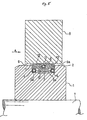
- Fig. 4 is a perspective view showing a main portion of a preferred embodiment of a hub setting device constructed according to the present invention; and
- Fig. 5 is a crosssection taken on a line V-Vin Fig. 1.
- Referring to the drawings, a detailed description of preferred embodiments according to the present invention will be given.
- Fig. 4 is a perspective view of a hub setting device constructed according to the present invention, and Fig. 5 is a cross section taken on a line V-V in Fig. 4.
- A
boss member 1 shown in Figs. 4 and 5 is arranged to suitably engage arotary shaft 7 so as to rotate similarly to theconventional boss member 14. A recess portion 3 is circumferentially formed in the center of the outer circumferential surface of theboss member 1, with a width of, for example, about one-third that of theboss member 1. Elastic members 4 are provided under positional restriction in receiving grooves 3a formed at the right and left ends of the recess portion 3. A dividedring 10 is provided over the elastic members 4, and aretention member 5 is provided around the outer circumference of the dividedring 10 so as to prevent the dividedring 10 from coming out of the recess portion 3. - The divided
ring 10 has a plate-like shape with an arcuate engagement surface 12 which comes into face-to-face contact with an inner circumferential surface 9 of thehub 8. The dividedring 10 is restricted in movement in the direction of the ring's width by the side surfaces of the recess portion 3. In the embodiment illustrated in Fig. 4, the dividedring 10 is arranged so as to make a circuit around the circumference of the recess portion 3, with the dividedring 10 being divided into four parts. A groove 11 is formed in the engagement surface 12 of the dividedring 10 at its longitudinally central portion so as to receive theretention member 5 therein. Ring edge portions 13 of theretention ring 5 in the longitudinally opposite ends thereof are formed as curved surfaces with a suitable curvature. - Although the material of the divided
ring 10 is not specifically limited, the dividedring 10 may be made of, for example, aluminum or the like, and it may be subjected to processing such as hard plating or the like so as to prevent the ring from being scratched. - Although conventional O-rings may be used as the above-mentioned elastic members 4, alternatively, it is possible to use hollow tubular members, for example, silicon tubes SR-No. 1 produced by Shinetsu Polymer Co., Ltd. The silicon tubes need not always be endless O-rings. Having a hollow structure, the silicon tubes are superior in their quantity of deformation and in elasticity, and hence in their action of urging the divided
ring 10 outward from the boss member. - The
retention member 5 is not specifically limited and other devices, for example, a coil spring, an O-ring, or the like may be used so long as it has suitable elasticity. Theretention member 5 is provided in a state where it is completely received in the groove 11, that is, it should not project out of the engagement surface 12 of the dividedring 10. It is preferable that the urging force of theretention member 5 pressing against the dividedring 10 not be too strong to prevent the latter from being suitably moved in the radial direction of theboss member 1 by the elasticity of the elastic member 4. - When the
hub 8 is inserted onto the thus-arranged boss member 1 (in the direction of an arrow A), aninner edge portion 9a of thehub 8 comes into contact with the ring-edge portion 13 of the dividedring 10. At the time of contact, theinner edge portion 9a is prevented from being caught by the ring-edge portion 13 because the ring-edge portion 13 is curved so that the dividedring 10 is pressed smoothly into the recess portion 3. Thus, the attachment of thehub 8 can very easily be carried out. Moreover, the mountedhub 8 is very surely retained on theboss member 1, the accurate rotation of thehub 8 is ensured, and deviations in rotation are prevented because the engagement surface 12 of the dividedring 10, which is recessed outward from the boss member by the elastic members 4, engages the inner circumferential surface 9 over a wide engagement area and the position of the dividedring 10 is surely restricted in the recess portion 3 with no play. That is, since nocoil springs 18 are in line contact with the inner circumferential surface 9 of thehub 8 as in the conventional arrangement, it is possible to avoid the above-discussed problems in the prior art, namely, generation of chips caused by rubbing between the inner circumferential surface 9 and thecoil springs 18 due to play of the hub during attachment/removal of the hub or during rotation of the hub, deterioration in the hub retention force due to abrasion of thecoil springs 18, etc. - The present invention is not limited to the embodiment described above, and may be modified in various ways, for example, in the shape and number of divided
rings 10, in the shape of the recess portion 3, in the use of other elastic members, etc. - As described above, the hub setting device according to the present invention is arranged so that the plate-like divided ring member acting elastically in the radial direction of the boss member and accurately restricted in position in the outer circumferential surface of the boss member is in contact over a wide area with the inner circumferential surface of the hub around which magnetic tape is to be wound. The hub is therefore surely retained without play, and deviations in the rotational movement of the hub are suppressed, making it possible to carry out winding of the tape with accurately registered tape edges. Further, the circumferential edge portions of the divided ring are formed as curved surfaces, and at least portions of the divided ring which contact the hub are hard- plated so that the hub insertion property is improved and the abrasion of the hub retaining surface (engagement surface) is prevented, thereby suppressing the generation of chips and ensuring good retention of the hub over long periods.
Claims (5)
characterized in that
said engagement member (10) is a ring circumferentially divided in parts, the device furthermore comprising retention means (5) for preventing the parts from coming out of the recess (3).
Applications Claiming Priority (2)
| Application Number | Priority Date | Filing Date | Title |
|---|---|---|---|
| JP62165514A JPH0784280B2 (en) | 1987-07-03 | 1987-07-03 | Hub setting device |
| JP165514/87 | 1987-07-03 |
Publications (4)
| Publication Number | Publication Date |
|---|---|
| EP0297609A2 EP0297609A2 (en) | 1989-01-04 |
| EP0297609A3 EP0297609A3 (en) | 1990-04-18 |
| EP0297609B1 true EP0297609B1 (en) | 1993-10-13 |
| EP0297609B2 EP0297609B2 (en) | 1996-12-11 |
Family
ID=15813843
Family Applications (1)
| Application Number | Title | Priority Date | Filing Date |
|---|---|---|---|
| EP88110573A Expired - Lifetime EP0297609B2 (en) | 1987-07-03 | 1988-07-01 | Hub setting device |
Country Status (4)
| Country | Link |
|---|---|
| US (1) | US4854518A (en) |
| EP (1) | EP0297609B2 (en) |
| JP (1) | JPH0784280B2 (en) |
| DE (1) | DE3884864T3 (en) |
Families Citing this family (10)
| Publication number | Priority date | Publication date | Assignee | Title |
|---|---|---|---|---|
| KR900007471Y1 (en) * | 1988-01-25 | 1990-08-18 | 주식회사 에스 케이 씨 | Winding reelholder for video pancake |
| DE4009849A1 (en) * | 1990-01-15 | 1991-07-18 | Windmoeller & Hoelscher | REEL SHAFT |
| GB2244696B (en) * | 1990-06-08 | 1994-06-08 | Otari Kk | Magnetic tape winding apparatus |
| DE4121244A1 (en) * | 1991-06-27 | 1993-01-07 | Basf Magnetics Gmbh | WINDING CORE TENSIONER |
| DE9115762U1 (en) * | 1991-12-19 | 1992-02-20 | Basf Magnetics Gmbh, 6800 Mannheim, De | |
| DE59309033D1 (en) * | 1992-02-06 | 1998-11-12 | Emtec Magnetics Gmbh | Winding device for magnetic tapes |
| DE9302492U1 (en) * | 1993-02-20 | 1993-04-15 | Basf Magnetics Gmbh, 6800 Mannheim, De | |
| DE4447032C2 (en) * | 1994-12-28 | 1998-03-26 | Emtec Magnetics Gmbh | Winding device for tape-shaped recording media |
| DE4447031C2 (en) * | 1994-12-28 | 1998-04-16 | Emtec Magnetics Gmbh | Winding device for tape-shaped recording media |
| US5683058A (en) * | 1996-03-05 | 1997-11-04 | Minnesota Mining And Manufacturing Company | Roll supporting hub |
Family Cites Families (11)
| Publication number | Priority date | Publication date | Assignee | Title |
|---|---|---|---|---|
| US3073610A (en) * | 1961-10-19 | 1963-01-15 | Lincoln Park Engineering Inc | Expanding arbor |
| US3445076A (en) * | 1967-08-02 | 1969-05-20 | Herbert F Dalglish | Core chuck |
| US3917187A (en) * | 1974-07-12 | 1975-11-04 | Lawrence R Damour | Expanding mandrel or chuck |
| US3937412A (en) * | 1975-04-23 | 1976-02-10 | Damour Lawrence R | Expanding outer sleeve for a mandrel or chuck |
| US4114909A (en) * | 1976-03-22 | 1978-09-19 | Jrc Products, Inc. | Core locking device |
| JPS5642857Y2 (en) * | 1976-06-22 | 1981-10-07 | ||
| US4124173A (en) * | 1977-01-11 | 1978-11-07 | Damour Lawrence R | Expanding outer sleeve for a mandrel or chuck |
| JPS583802Y2 (en) * | 1977-06-22 | 1983-01-22 | 富士写真フイルム株式会社 | Winding shaft for holding the winding core |
| US4220291A (en) * | 1979-08-27 | 1980-09-02 | Papa Robert B | Apparatus for winding tape on cores |
| US4438888A (en) * | 1982-03-10 | 1984-03-27 | International Business Machines Corp. | Self-aligning web reel |
| GB2137590A (en) * | 1983-04-07 | 1984-10-10 | Linotype Paul Ltd | Reel support |
-
1987
- 1987-07-03 JP JP62165514A patent/JPH0784280B2/en not_active Expired - Lifetime
-
1988
- 1988-06-30 US US07/213,561 patent/US4854518A/en not_active Expired - Lifetime
- 1988-07-01 EP EP88110573A patent/EP0297609B2/en not_active Expired - Lifetime
- 1988-07-01 DE DE3884864T patent/DE3884864T3/en not_active Expired - Lifetime
Also Published As
| Publication number | Publication date |
|---|---|
| EP0297609A2 (en) | 1989-01-04 |
| JPH0784280B2 (en) | 1995-09-13 |
| DE3884864T2 (en) | 1994-02-03 |
| DE3884864D1 (en) | 1993-11-18 |
| US4854518A (en) | 1989-08-08 |
| DE3884864T3 (en) | 1997-04-10 |
| EP0297609B2 (en) | 1996-12-11 |
| EP0297609A3 (en) | 1990-04-18 |
| JPS6413350A (en) | 1989-01-18 |
Similar Documents
| Publication | Publication Date | Title |
|---|---|---|
| EP0297609B1 (en) | Hub setting device | |
| US4313551A (en) | Tape guide apparatus | |
| US7240595B2 (en) | Process for producing magnetic tape | |
| JP3143523B2 (en) | Core tightening device | |
| EP0277301A1 (en) | Liner sheet for magnetic tape cassettes | |
| JP3000879U (en) | Film winding device with hub alignment | |
| JP3292737B2 (en) | Burnishing method for magnetic disk | |
| US5044574A (en) | Reel hub latch assembly | |
| JP2003115142A (en) | Guide assembly for reducing lateral movement of storage tape | |
| JPH0519906Y2 (en) | ||
| GB2214270A (en) | A reel holder for a device for manufacturing video pancakes | |
| GB2026436A (en) | Magnetic tape cassette | |
| JP3567660B2 (en) | Winding method and winding device | |
| JPS58208958A (en) | Tape running guide shaft and its manufacture | |
| JPH03256964A (en) | Thin web conveyor roll | |
| JPH09180395A (en) | Belt-driven type tape cartridge | |
| KR200148530Y1 (en) | Pancake hub | |
| JP2004342177A (en) | Magnetic tape, tape cartridge, and magnetic tape drive | |
| JPH0668412A (en) | Magnetic head grinding device | |
| JP3006086B2 (en) | Surface treatment device for manufacturing magnetic recording media and wrapping tape used for the same | |
| US20020089792A1 (en) | Rotating drum and magnetic tape drive using the same | |
| JPH04121853A (en) | Tape supply speed detector | |
| JPH01294208A (en) | Polishing device for tape slide face of magnetic head | |
| JPH0559675U (en) | Magnetic tape cassette | |
| JPH05151742A (en) | Tape cassette |
Legal Events
| Date | Code | Title | Description |
|---|---|---|---|
| PUAI | Public reference made under article 153(3) epc to a published international application that has entered the european phase |
Free format text: ORIGINAL CODE: 0009012 |
|
| AK | Designated contracting states |
Kind code of ref document: A2 Designated state(s): DE GB NL |
|
| PUAL | Search report despatched |
Free format text: ORIGINAL CODE: 0009013 |
|
| AK | Designated contracting states |
Kind code of ref document: A3 Designated state(s): DE GB NL |
|
| 17P | Request for examination filed |
Effective date: 19900515 |
|
| 17Q | First examination report despatched |
Effective date: 19911211 |
|
| GRAA | (expected) grant |
Free format text: ORIGINAL CODE: 0009210 |
|
| AK | Designated contracting states |
Kind code of ref document: B1 Designated state(s): DE GB NL |
|
| REF | Corresponds to: |
Ref document number: 3884864 Country of ref document: DE Date of ref document: 19931118 |
|
| PLBI | Opposition filed |
Free format text: ORIGINAL CODE: 0009260 |
|
| 26 | Opposition filed |
Opponent name: BASF MAGNETICS GMBH WERK MUENCHEN Effective date: 19940629 |
|
| NLR1 | Nl: opposition has been filed with the epo |
Opponent name: BASF MAGNETICS GMBH.WERK MUENCHEN. |
|
| PLAW | Interlocutory decision in opposition |
Free format text: ORIGINAL CODE: EPIDOS IDOP |
|
| PLAW | Interlocutory decision in opposition |
Free format text: ORIGINAL CODE: EPIDOS IDOP |
|
| PUAH | Patent maintained in amended form |
Free format text: ORIGINAL CODE: 0009272 |
|
| STAA | Information on the status of an ep patent application or granted ep patent |
Free format text: STATUS: PATENT MAINTAINED AS AMENDED |
|
| 27A | Patent maintained in amended form |
Effective date: 19961211 |
|
| AK | Designated contracting states |
Kind code of ref document: B2 Designated state(s): DE GB NL |
|
| NLR2 | Nl: decision of opposition | ||
| NLR3 | Nl: receipt of modified translations in the netherlands language after an opposition procedure | ||
| REG | Reference to a national code |
Ref country code: GB Ref legal event code: IF02 |
|
| REG | Reference to a national code |
Ref country code: GB Ref legal event code: 732E |
|
| PGFP | Annual fee paid to national office [announced via postgrant information from national office to epo] |
Ref country code: DE Payment date: 20070628 Year of fee payment: 20 |
|
| PGFP | Annual fee paid to national office [announced via postgrant information from national office to epo] |
Ref country code: GB Payment date: 20070627 Year of fee payment: 20 |
|
| PGFP | Annual fee paid to national office [announced via postgrant information from national office to epo] |
Ref country code: NL Payment date: 20070715 Year of fee payment: 20 |
|
| REG | Reference to a national code |
Ref country code: GB Ref legal event code: PE20 Expiry date: 20080630 |
|
| NLV7 | Nl: ceased due to reaching the maximum lifetime of a patent |
Effective date: 20080701 |
|
| PG25 | Lapsed in a contracting state [announced via postgrant information from national office to epo] |
Ref country code: GB Free format text: LAPSE BECAUSE OF EXPIRATION OF PROTECTION Effective date: 20080630 Ref country code: NL Free format text: LAPSE BECAUSE OF EXPIRATION OF PROTECTION Effective date: 20080701 |