EP0297338A1 - Sagnac optical fibre interferometer - Google Patents
Sagnac optical fibre interferometer Download PDFInfo
- Publication number
- EP0297338A1 EP0297338A1 EP88109380A EP88109380A EP0297338A1 EP 0297338 A1 EP0297338 A1 EP 0297338A1 EP 88109380 A EP88109380 A EP 88109380A EP 88109380 A EP88109380 A EP 88109380A EP 0297338 A1 EP0297338 A1 EP 0297338A1
- Authority
- EP
- European Patent Office
- Prior art keywords
- beams
- photodetector
- interferometric
- light
- optical fiber
- Prior art date
- Legal status (The legal status is an assumption and is not a legal conclusion. Google has not performed a legal analysis and makes no representation as to the accuracy of the status listed.)
- Granted
Links
Images
Classifications
-
- G—PHYSICS
- G01—MEASURING; TESTING
- G01C—MEASURING DISTANCES, LEVELS OR BEARINGS; SURVEYING; NAVIGATION; GYROSCOPIC INSTRUMENTS; PHOTOGRAMMETRY OR VIDEOGRAMMETRY
- G01C19/00—Gyroscopes; Turn-sensitive devices using vibrating masses; Turn-sensitive devices without moving masses; Measuring angular rate using gyroscopic effects
- G01C19/58—Turn-sensitive devices without moving masses
- G01C19/64—Gyrometers using the Sagnac effect, i.e. rotation-induced shifts between counter-rotating electromagnetic beams
- G01C19/72—Gyrometers using the Sagnac effect, i.e. rotation-induced shifts between counter-rotating electromagnetic beams with counter-rotating light beams in a passive ring, e.g. fibre laser gyrometers
-
- G—PHYSICS
- G01—MEASURING; TESTING
- G01R—MEASURING ELECTRIC VARIABLES; MEASURING MAGNETIC VARIABLES
- G01R15/00—Details of measuring arrangements of the types provided for in groups G01R17/00 - G01R29/00, G01R33/00 - G01R33/26 or G01R35/00
- G01R15/14—Adaptations providing voltage or current isolation, e.g. for high-voltage or high-current networks
- G01R15/24—Adaptations providing voltage or current isolation, e.g. for high-voltage or high-current networks using light-modulating devices
- G01R15/245—Adaptations providing voltage or current isolation, e.g. for high-voltage or high-current networks using light-modulating devices using magneto-optical modulators, e.g. based on the Faraday or Cotton-Mouton effect
- G01R15/246—Adaptations providing voltage or current isolation, e.g. for high-voltage or high-current networks using light-modulating devices using magneto-optical modulators, e.g. based on the Faraday or Cotton-Mouton effect based on the Faraday, i.e. linear magneto-optic, effect
Definitions
- the present invention relates to Sagnac type interferometric systems used in gyrometry or for current measurement by Faraday effect.
- interferometric systems use two light beams coming from the same source, generally a laser type diode, traveling in opposite directions on the same optical path consisting of a single-mode optical fiber before interfering with a photodetector. They make it possible to highlight the non-reciprocal phase modifications which depend on the directions of propagation of the beams and which are due either to the Sagnac effect in the case of gyrometry or to the Faraday effect in the case of the current measurement , this to the detriment of the reciprocal phase modifications which are due to the various disturbances encountered by the beams during their passage in the interferometric ring and which are eliminated by compensation at the level of the photodetector.
- the optical power of the two beams at the photodetector has a continuous component and a component proportional to the cosine of their relative phase shift, which has the disadvantage of giving the photodetector a cosinoid detection law with zero sensitivity to the origin.
- This phase modulation makes it possible to obtain, at the photodetector, as described in French patent application FR-A-2,471,583, a signal having a frequency component 1 / 2 ⁇ which is proportional to the sine of the relative phase shift of the two beams and for which the sensitivity is maximum at the origin, in the range of small relative phase shifts.
- Sagnac type interferometric systems used in gyrometry or for current measurement by Faraday effect in addition the fact that they use a phase modulation of the light beams comprises, as a rule, a Y coupler in integrated optics realizing the separation of the light wave from the source into two beams before its entry into the optical fiber constituting the interferometric ring and the recombination of the two beams at the output of the interferometric ring, and a directional coupler carrying out the separation of the light wave coming from the source and the two return beams of the interferometric ring.
- the semiconductor diode is switched so as to periodically emit the longest possible light pulses, that is to say of duration just less than the time ⁇ ′ of propagation of the two beams over all of their round trip.
- the switching period 2 ⁇ ′ is then very close to that of phase 2 ⁇ of the phase modulation used to optimize the sensibility of detection because the outward and return path made by the beams between the light source and the interferometric loop is small compared to that of the interferometric loop itself. This results in the signal photodetector output, an overlap of the various components due to the modulation coming from the switching of the source and to the phase modulation which makes it difficult to detect the useful signal.
- the present invention aims to solve the aforementioned problem without adding a significant length of optical fiber so as not to increase the size of the interferometric system or reduce the light energy efficiency.
- an interferometric fiber optic system of the Sagnac type which comprises: - an optical fiber forming an interferometric ring, - a collinear light source and photodetector, - optical coupling means making it possible to divide the light wave emitted by the source into two beams each applied to one end of the optical fiber forming the interferometric ring and to combine the two beams emerging from this optical fiber into a collinear light wave with that emitted by the source but in the opposite direction, and directed towards the photodetector, means for phase modulation imposing on the two beams circulating in the optical fiber forming the interferometric ring a periodic and symmetrical phase modulation, - amplitude modulation means acting on the emission power of the light source and - Electronic means for processing the photodetector signal comprising a demodulator operating at the frequency of the lower beat of the phase modulation frequency of the beams and the amplitude modulation frequency of the light source.
- the interferometric system shown comprises an optical plate 100 connected to the two ends of a single-mode optical fiber 200 constituting an interferometric ring and to an electronic plate 300.
- the optical stage 100 comprises a laser diode 101 emitting by its front and rear faces, coupled by its front face to a circuit in integrated optical technology 102 ensuring the functions of polarizer, mode filter, Y coupler and phase modulator , and by its rear face to a photodetector 103.
- the integrated optics circuit 102 is conventionally produced by means of an electro-optical substrate carrying solid light guides arranged in Y and electrodes between which an electric field can develop. It has a common input-output port 104 which is coupled to the front face of the laser diode 101 and two bypass input-output ports 105, 106 coupled to the ends of the optical fiber 200 constituting the interferometric ring.
- the common input-output port 104 constitutes the end of a solid monomode light guide 107 with polarization maintenance transformed into a polarizer in the region 108 by a conventional technique of doping by proton exchange or metallic deposition.
- This solid light guide 107 leads to a Y-junction with two other solid light guides 109 and 110 with polarization maintenance leading to the bypass input-output ports 105 and 106.
- the junction ensures a balanced sharing of the light energy reaching it by the solid light guide 107 between the two light guides 109 and 110 which each pass between a pair of electrodes 111, 112, 113, 114 between which one can develop an electric field locally modifying the refractive index of the optical material to modulate in phase the light beams.
- the single-mode optical fiber 200 constituting the interferometric ring is either a single-mode optical fiber with polarization maintenance in the case of a gyrometer where the Sagnac effect is implemented in an interferometric ring traversed by linearly polarized counterpropagative light beams, that is to say a single-mode optical fiber with very strong circular birefringence with end loops acting as quarter-wave filters in the case of a current measurement where l 'Faraday effect is implemented in an interferometric ring traversed by counterpropagative light beams with circular polarization.
- the light emitted on the front face of the laser diode 101 enters the integrated optical circuit 102 by the common input-output port 104, undergoes mode filtering and linear polarization in the solid guide of light 107, and is divided into two light beams with linear polarization which each emerge by a bypass input-output port 105, 106.
- These two light beams travel in opposite directions the optical fiber 200 constituting the interferometric ring and exit therefrom with a certain relative phase shift to re-enter the integrated optics circuit 102 by the bypass input-output ports, be united and undergo mode filtering. They then return to the laser diode which they pass through and strike the photodetector 103 mixed with the light wave directly emitted by the rear face of the laser diode.
- phase modulation is obtained by electro-optical effect by creating between the pairs of electrodes 111, 112, 113, 114 an electric field pulsed at the half resonant frequency of the ring of the interferometer called natural frequency of the interferometer.
- the addition of this phase modulation has the effect of transforming the expression of the light power P of the two light beams returning from the interferometric ring as follows: ⁇ being a modulation index and ⁇ the travel time of the interferometric ring by a light beam.
- This light power has a frequency spectrum rich in components with in particular: - a continuous component, a component at the frequency 1/2 ⁇ of the phase modulation, proportional to the sine of the relative phase shift ⁇ ⁇ giving maximum sensitivity in the range of small relative phase shifts, - a component at double 1/2 of the phase modulation frequency, which is proportional to the cosine of the relative phase shift ⁇ ⁇ and is canceled with the latter.
- the relative phase shift of the two return light beams of the interferometric ring is measured from a component to the frequency 1/2 ⁇ extracted from the photodetector signal by a synchronous demodulation.
- the laser diode and the photo-detector are aligned or made up of the same element, it is usual to cause the laser diode to emit periodic light pulses of duration shorter than their return time and to detect the optical power of the pulse return. either using the laser diode transformed into a photodetector between the emission of two light pulses either using a photodetector receiving the pulse feedback passing through the laser diode from its front face to its rear face.
- This component which exists as long as the two modulation frequencies are slightly different, can be used for the measurement of the relative phase shift of the two beams with a maximum sensitivity for small phase shifts.
- the electronic circuit board 300 makes it possible to implement the two amplitude and phase modulations to generate this component, to isolate it and to use it to derive the value of the relative phase shift between the two return beams of the interferometric ring. It can be broken down into an emission part generating the electrical signals necessary for the double amplitude and phase modulation of the two counterpropagative light beams traversing the interferometric ring, into a reception part.
- the thermal regulation of the optical plate 100 is ensured by a regulation block 302 coupled with the temperature measurement elements 115 of the optical plate 100.
- the transmission part includes a modulator 303 of the optical power of the laser diode 101 and a frequency synthesizer generator 304.
- the power modulator 303 is stabilized by a feedback loop including the photodetector 103 coupled to the rear face of the laser diode 101. It is provided with a modulation carrier input f1 controlled by an output of the frequency synthesizer 304 This frequency synthesizer 304 controls by a second output on which it delivers a frequency f2 equal to 1 / 2 ⁇ , the pairs of electrodes 111, 112, 113, 114 of the phase optical modulators of the circuit in integrated optics 102 and, by a third output on which it delivers a frequency
- the reception part comprises the synchronous demodulation circuit 305 preceded by an amplification and filtering circuit 307 connected to the output of the photodetector 103 coupled to the rear face of the laser diode 101 and followed by another amplification circuit and filter 308.
- the photodetector 103 coupled to the rear face of the laser diode 101 delivers a signal proportional to the light power it receives from the laser diode either directly or after passing in the interferometric ring and crossed back by the laser diode.
- This signal includes: a main component at the frequency f1 for modulating the light power emitted by the diode due to the light flux received directly from the laser diode by its rear face, - and a much lower amplitude component from the beating of the two counterpropagative light beams which are modulated both in amplitude and in phase and which have passed through the laser diode upon their return from the interferometric ring, this component verifying as saw it before, a relation of the form.
- circuit 307 It is filtered and amplified by circuit 307 to derive a component at the frequency
- which is, as mentioned earlier in the form: and which, applied to the synchronous demodulator 305 then filtered and amplified by the circuit 77 gives rise to a relative phase shift measurement signal of the form: s (t) k sin ⁇ ⁇ (t)
- This technique makes it possible to use an amplitude modulation frequency f1 close to that of phase modulation f2.
- the natural frequency of the interferometer and therefore of the phase modulation is order of 100 KHz and one can consider an amplitude modulation frequency of the light energy of the near laser diode, of the order of 98 KHz.
- the interferometric ring is a single mode optical fiber with very strong circular birefringence of ten meters long giving rise to a natural frequency of the interferometer therefore phase modulation of the order of 10 MHz it is possible to envisage a frequency of amplitude modulation of the light energy of the laser of the order of 9.95 MHz.
- This allows under the conditions of amplitude modulation by all or nothing of the laser diode to separate the transmitted pulse and its return to the photodetector to not have to lengthen the path of the light beam between the laser diode and l interferometric ring with a fiber length of the order of 25 cm instead of the 2.5 meters of the previous solution.
- the relative phase shift measurement signal s (t) available at the output of the amplifier circuit 308 is sampled and digitized by an analog-digital converter 309 which comprises a sampler-blocker and an analog-digital conversion device operating according to the usual techniques.
- the digital processing part of the signal from the electronic circuit board 300 includes a processing processor 310, a communication processor 311 and the clock circuit 306.
- the main role of the processing processor 310 is to extract from the signal s (t) of the reception part, available in digital form at the output of the analog-digital converter 309, an explicit value of the relative phase shift of the two counterpropagative light beams originating from the interferometric ring and to deduce therefrom either an angular speed value in the event of gyrometry or a current intensity value in the event of current measurement by Faraday effect by exploiting the relations of definition of the Sagnac effect or of the Faraday effect.
- the communication processor 311 ensures the coding, the serialization and the digital transmission of the result of the instantaneous measurement delivered by the processing processor 310, the transmission being made to the outside by means of a light-emitting diode 312 and a fiber. single-mode or multi-mode optics 313.
- the clock circuit 306 receives external synchronization via another single-mode or multi-mode optical fiber 314 useful in the case where the interferometric system must operate in synchronism with other apparatus. It also delivers a stable clock signal used by the frequency synthesizer generator 304 of the transmission part to develop the modulation carriers f1, f2 as well as the demodulation carrier (f1-f2) suitably out of phase to ensure correct operation of the circuit. synchronous demodulation 305.
Abstract
Ce système interféromètrique à fibre optique est employé soit en gyrométrie soit en mesure de courant par effet Faraday. Il comporte une platine optique (100) qui est raccordée aux deux extrémités d'une fibre optique monomode (200) constituant un anneau interférométrique et dans laquelle le photodétecteur (103) est colinéaire à la source lumineuse couplée par ses faces avant et arrière. Les deux faisceaux contrapropagatifs parcourant l'anneau interférométrique ont leur écart de phase relatif modulé par une modulation de phase et leur puissance lumineuse modulée par une modulation d'amplitude. Une platine électronique (300) engendre ces modulations et extrait du signal du photodétecteur (103) une composante à la fréquence du battement inférieur de ces deux modulations permettant de mesurer l'écart de phase relatif des deux faisceaux.This fiber optic interferometric system is used either in gyrometry or in current measurement by Faraday effect. It comprises an optical plate (100) which is connected to the two ends of a single mode optical fiber (200) constituting an interferometric ring and in which the photodetector (103) is collinear with the light source coupled by its front and rear faces. The two counterpropagative beams traversing the interferometric ring have their relative phase difference modulated by a phase modulation and their light power modulated by an amplitude modulation. An electronic circuit board (300) generates these modulations and extracts from the photodetector signal (103) a component at the frequency of the lower beat of these two modulations making it possible to measure the relative phase difference of the two beams.
Description
La présente invention concerne les systèmes interférométriques de type Sagnac employés en gyrométrie ou pour la mesure de courant par effet Faraday.The present invention relates to Sagnac type interferometric systems used in gyrometry or for current measurement by Faraday effect.
Ces systèmes interférométriques utilisent deux faisceaux lumineux issus d'une même source, généralement une diode de type laser, parcourant en sens opposés un même chemin optique constitué d'une fibre optique monomode avant d'interférer sur un photodétecteur. Ils permettent de mettre en évidence les modifications de phase non réciproques qui dépendent des sens de propagation des faisceaux et qui sont dues soit à l'effet Sagnac dans le cas de la gyrométrie soit à l'effet Faraday dans le cas de la mesure de courant, cela au détriment des modifications de phase réciproques qui sont dues aux différentes perturbations rencontrées par les faisceaux au cours de leur cheminement dans l'anneau interférométrique et qui s'éliminent par compensation au niveau du photodétecteur.These interferometric systems use two light beams coming from the same source, generally a laser type diode, traveling in opposite directions on the same optical path consisting of a single-mode optical fiber before interfering with a photodetector. They make it possible to highlight the non-reciprocal phase modifications which depend on the directions of propagation of the beams and which are due either to the Sagnac effect in the case of gyrometry or to the Faraday effect in the case of the current measurement , this to the detriment of the reciprocal phase modifications which are due to the various disturbances encountered by the beams during their passage in the interferometric ring and which are eliminated by compensation at the level of the photodetector.
Sans disposition particulière, la puissance optique des deux faisceaux au niveau du photodétecteur présente une composante continue et une composante proportionnelle au cosinus de leur déphasage relatif ce qui a l'inconvénient de donner au photodétecteur une loi de détection cosinoïdale avec une sensibilité nulle à l'origine. Pour éliminer cet inconvénient, il est habitual d'imposer aux deux faisceaux circulant dans l'anneau interférométrique, une modulation de phase périodique et symétrique avec une périodicité double 2τ du temps τ mis par les faisceaux pour parcourir l'anneau interférométrique. Cette modulation de phase permet d'obtenir, au niveau du photodétecteur, comme décrit dans la demande de brevet français FR-A-2.471.583, un signal présentant une composante de fréquence 1/2τ qui est proportionnelle au sinus du déphasage relatif des deux faisceaux et pour laquelle la sensibilité est maximale à l'origine, dans la plage des petits déphasages relatifs.Without any particular arrangement, the optical power of the two beams at the photodetector has a continuous component and a component proportional to the cosine of their relative phase shift, which has the disadvantage of giving the photodetector a cosinoid detection law with zero sensitivity to the origin. To eliminate this drawback, it is customary to impose on the two beams circulating in the interferometric ring, a periodic and symmetrical phase modulation with a double periodicity 2τ of the time τ taken by the beams to traverse the interferometric ring. This phase modulation makes it possible to obtain, at the photodetector, as described in French patent application FR-A-2,471,583, a signal having a
Les systèmes interférométriques de type de Sagnac employés en gyrométrie ou pour la mesure de courant par effet Faraday outre le fait qu'ils utilisent une modulation de phase des faisceaux lumineux comportent, en régle générale, un coupleur en Y en optique intégrée réalisant la séparation de l'onde lumineuse de la source en deux faisceaux avant son entrée dans la fibre optique constituant l'anneau interférométrique et la recombinaison des deux faisceaux en sortie de l'anneau interférométrique, et un coupleur directif réalisant la séparation de l'onde lumineuse issue de la source et des deux faisceaux de retour de l'anneau interférométrique.Sagnac type interferometric systems used in gyrometry or for current measurement by Faraday effect in addition the fact that they use a phase modulation of the light beams comprises, as a rule, a Y coupler in integrated optics realizing the separation of the light wave from the source into two beams before its entry into the optical fiber constituting the interferometric ring and the recombination of the two beams at the output of the interferometric ring, and a directional coupler carrying out the separation of the light wave coming from the source and the two return beams of the interferometric ring.
Ces dispositifs en optique intégrée qui s'imposent par rapport aux solutions de l'optique classique en raison de leurs avantages : insensibilité aux vibrations, faible encombrement..., ont l'inconvénient d'avoir des coefficients d'absorption non négligeables et d'être relativement difficiles à réaliser. C'est pourquoi, on a déjà proposé, notamment dans la demande de brevet français FR-A-2.582.800, de supprimer le coupleur directif en combinant la source lumineuse et le photodétecteur de manière à les rendre colinéaires, soit que l'un et l'autre soient réalisés au moyen d'une unique diode semi-conductrice utilisée alternativement en émetteur et en détecteur d'énergie lumineuse soit que l'un et l'autre soient alignés, la source lumineuse étant constituée d'une diode semi-conductrice couplée par ses faces avant et arrière, intercalée entre le photodétecteur et le coupleur en Y, et utilisée alternativement en émetteur et en amplificateur d'énergie lumineuse.These devices in integrated optics which are essential compared to the solutions of conventional optics because of their advantages: insensitivity to vibrations, small footprint ..., have the disadvantage of having significant absorption coefficients and d 'be relatively difficult to achieve. This is why, it has already been proposed, in particular in French patent application FR-A-2,582,800, to delete the directional coupler by combining the light source and the photodetector so as to make them collinear, that is to say one and the other are made by means of a single semiconductor diode used alternately as an emitter and as a light energy detector, that is to say that the one and the other are aligned, the light source being constituted by a semi-diode conductive coupled by its front and rear faces, interposed between the photodetector and the Y coupler, and used alternately as a light energy emitter and amplifier.
Dans les deux cas, la diode semi-conductrice est commutée de façon à émettre périodiquement des impulsions lumineuses les plus longues possibles c'est-à-dire de durée juste inférieure au temps τ′ de propagation des deux faisceaux sur l'ensemble de leur trajet aller et retour. La période de commutation 2τ′ est alors très proche de celle 2τ de la modulation de phase utilisée pour optimiser la sensiblité de détection car le parcours aller et retour effectué par les faisceaux entre la source lumineuse et la boucle interférométrique est petit par rapport à celui de la boucle interférométrique elle-même. Il en résulte dans le signal de sortie du photodétecteur, un recouvrement des diverses composantes dues à la modulation provenant de la commutation de la source et à la modulation de phase qui rend difficile la détection du signal utile.In both cases, the semiconductor diode is switched so as to periodically emit the longest possible light pulses, that is to say of duration just less than the time τ ′ of propagation of the two beams over all of their round trip. The switching period 2τ ′ is then very close to that of phase 2τ of the phase modulation used to optimize the sensibility of detection because the outward and return path made by the beams between the light source and the interferometric loop is small compared to that of the interferometric loop itself. This results in the signal photodetector output, an overlap of the various components due to the modulation coming from the switching of the source and to the phase modulation which makes it difficult to detect the useful signal.
Dans la demande de brevet français FR-A-2.582.800 précitée, cette difficulté est tournée en doublant artificiellement le temps de propagation des deux faisceaux sur leur trajet aller et retour par adjonction,entre la source et le coupleur en Y, d'une longueur supplémentaire de fibre optique égale au quart de la longueur de celle formant la boucle interférométrique.In the above-mentioned French patent application FR-A-2,582,800, this difficulty is overcome by artificially doubling the propagation time of the two beams on their outward and return path by adding, between the source and the Y coupler, a additional length of optical fiber equal to a quarter of the length of that forming the interferometric loop.
La présente invention a pour but de résoudre le problème précité sans adjonction d'une longueur significative de fibre optique pour ne pas augmenter l'encombrement du système interférométrique ni amoindrir le rendement énergétique lumineux.The present invention aims to solve the aforementioned problem without adding a significant length of optical fiber so as not to increase the size of the interferometric system or reduce the light energy efficiency.
Elle a pour objet un système interférométrique à fibre optique de type Sagnac qui comporte :
- une fibre optique formant un anneau interférométrique,
- une source lumineuse et un photodétecteur colinéaires,
- des moyens de couplage optique permettant de diviser l'onde lumineuse émise par la source en deux faisceaux chacun appliqué à une extrémité de la fibre optique formant l'anneau interférométrique et de recombiner les deux faisceaux émergeant de cette fibre optique en une onde lumineuse colinéaire avec celle émise par la source mais de sens opposé, et dirigée vers le photodétecteur,
- des moyens de modulation de phase imposant aux deux faisceaux circulant dans la fibre optique formant l'anneau interférométrique une modulation de phase périodique et symétrique,
- des moyens de modulation d'amplitude agissant sur la puissance d'émission de la source lumineuse et
- des moyens électroniques de traitement du signal du photodétecteur comportant un démodulateur opérant à la fréquence du battement inférieur de la fréquence de modulation de phase des faisceaux et de la fréquence de modulation d'amplitude de la source lumineuse.It relates to an interferometric fiber optic system of the Sagnac type which comprises:
- an optical fiber forming an interferometric ring,
- a collinear light source and photodetector,
- optical coupling means making it possible to divide the light wave emitted by the source into two beams each applied to one end of the optical fiber forming the interferometric ring and to combine the two beams emerging from this optical fiber into a collinear light wave with that emitted by the source but in the opposite direction, and directed towards the photodetector,
means for phase modulation imposing on the two beams circulating in the optical fiber forming the interferometric ring a periodic and symmetrical phase modulation,
- amplitude modulation means acting on the emission power of the light source and
- Electronic means for processing the photodetector signal comprising a demodulator operating at the frequency of the lower beat of the phase modulation frequency of the beams and the amplitude modulation frequency of the light source.
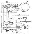
D'autres caractéristiques et avantages de l'invention ressortiront de la description ci-après d'un mode de réalisation donné à titre d'exemple. Cette description sera faite en regard du dessin dont la figure unique représente le schéma de principe de la partie optique et de la partie électronique d'un système d'interférométrique de Sagnac selon l'invention.Other characteristics and advantages of the invention will emerge from the description below of an embodiment given as example. This description will be made with reference to the drawing, the single figure of which represents the block diagram of the optical part and the electronic part of a Sagnac interferometric system according to the invention.
Le système interférométrique représenté comporte une platine optique 100 raccordée aux deux extrémités d'une fibre optique monomode 200 constituant un anneau interférométrique et à une platine électronique 300.The interferometric system shown comprises an
La platine optique 100 comporte une diode laser 101 émettant par ses faces avant et arrière, couplée par sa face avant à un circuit en technologie optique intégrée 102 assurant les fonctions de polariseur, de filtre de mode, de coupleur en Y et de modulateur de phase, et par sa face arrière à un photodétecteur 103.The
Le circuit en optique intégrée 102 est réalisé classiquement au moyen d'un substrat électro-optique portant des guides solides de lumière disposés en Y et des électrodes entre lesquelles peut se développer un champ électrique. Il possède un port d'entrée-sortie commun 104 qui est couplé à la face avant de la diode laser 101 et deux ports d'entrée-sortie de dérivation 105, 106 couplés aux extrémités de la fibre optique 200 constituant l'anneau interférométrique. Le port d'entrée-sortie commun 104 constitue l'extrémité d'un guide solide lumière monomode 107 à maintien de polarisation transformé en polariseur dans la région 108 par une technique classique de dopage par échange protonique ou de dépôt métallique. Ce guide solide de lumière 107 mène à une jonction en Y avec deux autres guides solides de lumière 109 et 110 monomodes à maintien de polarisation aboutissant aux ports d'entrée-sortie de dérivation 105 et 106.The integrated optics circuit 102 is conventionally produced by means of an electro-optical substrate carrying solid light guides arranged in Y and electrodes between which an electric field can develop. It has a common input-
La jonction assure un partage équilibré de l'énergie lumineuse lui parvenant par le guide solide de lumière 107 entre les deux guides de lumière 109 et 110 qui passent chacun entre une paire d'électrodes 111, 112, 113, 114 entre lesquelles on peut développer un champ électrique modifiant localement l'indice de réfraction du matériau optique pour moduler en phase les faisceaux lumineux.The junction ensures a balanced sharing of the light energy reaching it by the solid light guide 107 between the two
La fibre optique monomode 200 constituant l'anneau interférométrique est soit une fibre optique monomode à maintien de polarisation dans le cas d'une gyromètre ou l'effet Sagnac est mis en oeuvre dans un anneau interférométrique parcouru par des faisceaux lumineux contrapropagatifs à polarisation linéaire, soit une fibre optique monomode à très forte biréfringence circulaire avec des boucles d'extrémités jouant le rôle de filtres quart d'onde dans le cas d'une mesure de courant où l'effet Faraday est mis en oeuvre dans une anneau interférométrique parcouru par des faisceaux lumineux contrapropagatifs à polarisation circulaire.The single-mode
Dans ce montage optique, l'one lumineuse émise sur la face avant de la diode laser 101 pénètre dans le circuit en optique intégrée 102 par le port entrée-sortie commun 104, subit un filtrage de mode et une polarisation linéaire dans le guide solide de lumière 107, et est partagée en deux faisceaux lumineux à polarisation linéaire qui ressortent chacun par un port d'entrée-sortie de dérivation 105, 106. Ces deux faisceaux lumineux parcourent en sens opposés la fibre optique 200 constituant l'anneau interférométrique et en ressortent avec un certain déphasage relatif pour pénétrer à nouveau dans le circuit en optique intégrée 102 par les ports d'entrée-sortie de dérivation, être réunis et subir un filtrage de mode. Ils retournent ensuite à la diode laser qu'ils traversent et viennent frapper le photodétecteur 103 mélangés à l'onde lumineuse directement émise par la face arrière de la diode laser.In this optical assembly, the light emitted on the front face of the
La puissance optique P résultant de la recombinaison des deux faisceaux lumineux de puissances optiques respectives P1 et P2 qui ont parcouru en sens inverses la fibre optique constituant l'anneau interférométrique s'exprime par :
P = P1 + P2 + 2 √P1 P2 cos Δ φ
Δ φ étant le déphasage relatif du à l'effet Sagnac ou à l'effet Faraday sur les deux faisceaux lorsqu'ils parcourent la fibre optique 200 en sens opposés.The optical power P resulting from the recombination of the two light beams of respective optical powers P1 and P2 which have traversed in opposite directions the optical fiber constituting the interferometric ring is expressed by:
P = P1 + P2 + 2 √P1 P2 cos Δ φ
Δ φ being the relative phase shift due to the Sagnac effect or the Faraday effect on the two beams when they pass through the
Elle présente une composante utile proportionnelle au cos Δ φ ayant l'inconvénient d'aboutir à une sensibilité nulle pour les petits déphasages.It has a useful component proportional to the cos Δ φ having the drawback of achieving zero sensitivity for small phase shifts.
Pour améliorer cette sensibilité, il est connu de moduler l'angle de phase des deux faisceaux contrapropagatifs parcourant l'anneau interférométrique de manière à obtenir des écarts de phase instantanés égaux mais de signes opposés sur les deux faisceaux. Cette modulation de phase s'obtient par effet électro-optique en créant entre les paires d'électrodes 111, 112, 113, 114 un champ électrique pulsé à la demi-fréquence de résonance de l'anneau de l'interféromètre dite fréquence propre de l'interféromètre. L'ajout de cette modulation de phase a pour effet de tranformer l'expression de la puissance lumineuse P des deux faisceaux lumineux de retour de l'anneau interférométrique de la manière suivante :
Cette puissance lumineuse présente un spectre de fréquence riche en composantes avec notamment :
- une composante continue,
- une composante à la fréquence 1/2 τ de la modulation de phase, proportionnelle au sinus du déphasage relatif Δ φ donnant un maximum de sensibilité dans la plage des petits déphasages relatifs,
- une composante au double 1/2 de la fréquence de modulation de phase, qui est proportionnelle au cosinus du déphasage relatif Δ φ et s'annule avec ce dernier.This light power has a frequency spectrum rich in components with in particular:
- a continuous component,
a component at the
- a component at double 1/2 of the phase modulation frequency, which is proportional to the cosine of the relative phase shift Δ φ and is canceled with the latter.
Dans les montages optiques où la diode laser et le photodétecteur ne sont pas alignés mais montés à l'aide d'un coupleur directif, le déphasage relatif des deux faisceaux lumineux de retour de l'anneau interférométrique est mesuré à partir d'une composante à la fréquence 1/2 τ extraite du signal du photodétecteur par une démodulation synchrone.In optical assemblies where the laser diode and the photodetector are not aligned but mounted using a directional coupler, the relative phase shift of the two return light beams of the interferometric ring is measured from a component to the
Lorsque la diode laser et le photo-détecteur sont alignés ou constitués du même élément, il est habituel de faire émettre par la diode laser des impulsions lumineuses périodiques de durée inférieure à leur temps de retour et de détecter la puissance optique du retour d'impulsion soit à l'aide de la diode laser transformée en photodétecteur entre l'émission de deux impulsions lumineuses soit à l'aide d'un photodétecteur recevant le retour d'impulsion traversant la diode laser de sa face avant à sa face arrière.When the laser diode and the photo-detector are aligned or made up of the same element, it is usual to cause the laser diode to emit periodic light pulses of duration shorter than their return time and to detect the optical power of the pulse return. either using the laser diode transformed into a photodetector between the emission of two light pulses either using a photodetector receiving the pulse feedback passing through the laser diode from its front face to its rear face.
Pour avoir un bon rendement énergétique, on est conduit à adopter des durées d'émission d'impulsion lumineuse et de retour d'impulsion lumineuse maximales τ′ qui correspondent au double du temps de parcours τ˝ mis par la lumière pour aller de la diode laser à l'anneau interférométrique augmenté du temps de parcours τ dans l'anneau interférométrique
τ′ = 2 τ˝ + τTo have good energy efficiency, we are led to adopt maximum light pulse emission and light pulse return durations τ ′ which correspond to twice the travel time τ˝ taken by the light to go from the diode laser at the interferometric ring increased by the travel time τ in the interferometric ring
τ ′ = 2 τ˝ + τ
Il en résulte un période de commutation émission-réception double 2τ′ très proche de la période de modulation de phase 2τ dans la mesure où la distance entre la diode laser et l'anneau interférométrique est très inférieure à la longueur de cet anneau de sorte que l'on retrouve dans le spectre du signal engendré par le photodétecteur, au voisinage de la fréquence 1/2τ, des raies provoquées par la modulation due à la commutation émission-réception de la diode laser qui perturbent la détection de la raie utile à 1/2τ engendrée par la modulation de phase.This results in a double transmission-reception switching period 2τ ′ very close to the phase modulation period 2τ in so far as the distance between the laser diode and the interferometric ring is much less than the length of this ring so that one finds in the spectrum of the signal generated by the photodetector, in the vicinity of the
Pour éliminer cette perturbation il est connu d'éloigner la fréquence de commutation émission-réception de la diode laser de la fréquence de modulation de phase en prolongeant le trajet de l'impulsion lumineuse entre le diode laser et l'anneau interférométrique en intercalant sur ce trajet une longueur auxiliaire de fibre optique monomode de l'ordre du quart de la longeur de la fibre optique 200 constituant l'anneau interférométrique mais cela à l'inconvénient d'augmenter l'encombrement du dispositif et de diminuer le rendement énergétique lumineux.To eliminate this disturbance, it is known to distance the transmit-receive switching frequency of the laser diode from the phase modulation frequency by extending the path of the light pulse between the laser diode and the interferometric ring by inserting on this path an auxiliary length of single-mode optical fiber of the order of a quarter of the length of the
Selon la solution de l'invention, on propose d'isoler un signal utile dans une autre raie du signal issue du photodétecteur à la suite de la combinaison de la modulation de phase et de la modulatin résultant de la commutation émission-réception de la diode laser ou plus généralement d'une modulation de l'amplitude de l'énergie lumineuse émise par la diode laser.According to the solution of the invention, it is proposed to isolate a useful signal in another line of the signal from the photodetector following the combination of phase modulation and modulatin resulting from the transmission-reception switching of the diode laser or more generally a modulation of the amplitude of the light energy emitted by the laser diode.
En effet, une modulation sinuoïdale à la fréquence f1 de l'amplitude de l'énergie lumineuse émise par la diode laser se traduit sur l'énergie de chacun des deux faisceaux lumineux entrant dans l'anneau interférométrique par une loi de variation de la forme :
P1 = PO1 (1 + m sin 2 π f 1t)
P2 = PO2 (1 + m sin 2 π f 1t)
PO1 et PO2 étant des constantes et m un taux de modulation d'amplitude, de sorte que la puissance des deux faisceaux lumineux de retour de l'anneau interférométrique répond, compte tenu de la modulation de phase à une relation de la forme :
P1 = PO1 (1 + m sin 2 π f 1t)
P2 = PO2 (1 + m sin 2 π f 1t)
PO1 and PO2 being constants and m a rate of amplitude modulation, so that the power of the two light beams returning from the interferometric ring responds, taking into account the phase modulation to a relation of the form:
L'analyse mathématique de cette relation au moyen des fonctions de Bessel montre que la puissance optique P des faisceaux issus de l'anneau interférométrique possède un spectre de fréquence très riche en harmoniques avec une raie à la fréquence |![]()
![]()
(![]()
![]()
![]()
(( ![]()
Cette composante qui existe pour peu que les deux fréquences de modulation soit légèrement différentes, peut servir pour la mesure du déphasage relatif des deux faisceaux avec une sensibilité maximale pour les petits déphasages.This component which exists as long as the two modulation frequencies are slightly different, can be used for the measurement of the relative phase shift of the two beams with a maximum sensitivity for small phase shifts.
La platine d'électronique 300 permet de mettre en oeuvre les deux modulations d'amplitude et de phase pour engendrer cette composante, de l'isoler et de l'exploiter pour en tirer la valeur du déphasage relatif entre les deux faisceaux de retour de l'anneau interférométrique. Elle peut se décomposer en une partie émission engendrant les signaux électriques nécessaires à la double modulation d'amplitude et de phase des deux faisceaux lumineux contrapropagatifs parcourant l'anneau interférométrique, en une partie réception extrayant du battement des deux faisceaux contrapropagatifs de retour de l'anneau interférométrique un signal proportionnel à leur déphasage relatif, en une partie d'exploitation numérique du signal de la partie réception assurant également la transmission de la mesure vers l'extérieur du système interférométrique ainsi qu'une synchronisation éventuelle de cette mesure avec une référence temporelle externe, et en une partie de service comprenant une alimentation électrique 301 et une régulation thermique de la platine optique 100.The
La régulation thermique de la platine optique 100 est assurée par un bloc de régulation 302 couplé des éléments de mesure de température 115 de la platine optique 100.The thermal regulation of the
La partie émission comporte un modulateur 303 de la puissance optique de la diode laser 101 et un générateur synthétiseur de fréquence 304.The transmission part includes a
Le modulateur de puissance 303 est stabilisé par une boucle de contre-réaction incluant le photodétecteur 103 couplé à la face arrière de la diode laser 101. Il est pourvu d'une entrée de porteuse de modulation f1 contrôlée par une sortie du synthétiseur de fréquence 304. Ce synthétiseur de fréquence 304 pilote par une deuxième sortie sur laquelle il délivre une fréquence f2 égale 1/2τ , les paires d'électrodes 111, 112, 113, 114 des modulateurs optiques de phase du circuit en optique intégrée 102 et, par une troisième sortie sur laquelle il délivre une fréquence |f1 - f2| un circuit de démodulation synchrone 305 de la partie réception. Il présente également une entrée de synchronisation commandée par un circuit d'horloge 306 de la partie d'exploitation numérique du signal reçu.The
La partie réception comporte le circuit de démodulation synchrone 305 précédé d'un circuit d'amplification et de filtrage 307 relié à la sortie du photodétecteur 103 couplé à la face arrière de la diode laser 101 et suivi d'un autre circuit d'amplification et de filtrage 308.The reception part comprises the
Le photodétecteur 103 couplé à la face arrière de la diode laser 101 délivre un signal proportionnel à la puissance lumineuse qu'il reçoit de la diode laser soit directement soit après passage dans l'anneau interférométrique et traversée en retour de la diode laser. Ce signal comporte :
- une composante principale à la fréquence f1 de modulation de la puissance lumineuse émise par la diode due au flux lumineux reçu directement de la diode laser par sa face arrière,
- et une composante d'amplitude beaucoup plus faible provenant du battement des deux faisceaux lumineux contrapropagatifs qui sont modulés à la fois en amplitude et en phase et qui ont traversé la diode laser à leur retour de l'anneau interférométrique, cette composante vérifiant comme on l'a vu précédemment, une relation de la forme.
![]()
The
a main component at the frequency f1 for modulating the light power emitted by the diode due to the light flux received directly from the laser diode by its rear face,
- and a much lower amplitude component from the beating of the two counterpropagative light beams which are modulated both in amplitude and in phase and which have passed through the laser diode upon their return from the interferometric ring, this component verifying as saw it before, a relation of the form.
![]()
Il est filtré et amplifié par le circuit 307 pour en tirer une composante à la fréquence |f1 - f2| qui est, comme mentionné précédemment de la forme :
![]()
et qui, appliquée au démodulateur synchrone 305 puis filtrée et amplifiée par le circuit 77 donne naissance à un signal de mesure de déphasage relatif de la forme :
s (t) = k sin Δ φ (t)It is filtered and amplified by
![]()
and which, applied to the
s (t) = k sin Δ φ (t)
Cette technique permet d'utiliser une fréquence de modulation d'amplitude f1 proche de celle f2 de la modulation de phase. Dans le cas d'un gyromètre où l'on utilise pour l'anneau interférométrique une fibre optique monomode à maintien de polarisation de l'ordre du kilomètre, la fréquence propre de l'interféromètre et donc de la modulation de phase est de l'ordre de 100 KHz et l'on peut envisager une fréquence de modulation d'amplitude de l'énergie lumineuse de la diode laser proche, de l'ordre de 98 KHz. Cela permet, si l'on désire employer une modulation d'amplitude par tout ou rien pour séparer sur le photodétecteur l'impulsion émise et son retour, de n'avoir à rallonger que très faiblement les trajets des faisceaux lumineux sur leur parcours entre la diode laser et l'anneau interférométrique, ce rallongement étant dans l'exemple précité de l'ordre de 10 mètres de fibre au lieu des 250 dans la solution antérieure.This technique makes it possible to use an amplitude modulation frequency f1 close to that of phase modulation f2. In the case of a gyrometer where a single mode optical fiber with polarization maintenance of the order of a kilometer is used for the interferometric ring, the natural frequency of the interferometer and therefore of the phase modulation is order of 100 KHz and one can consider an amplitude modulation frequency of the light energy of the near laser diode, of the order of 98 KHz. This allows, if one wishes to use an amplitude modulation by all or nothing to separate on the photodetector the pulse emitted and its return, to have to lengthen only very slightly the paths of the light beams on their path between the laser diode and the 'interferometric ring, this extension being in the above example of the order of 10 meters of fiber instead of 250 in the previous solution.
De même dans le cas d'un appareil de mesure de courant par effet Faraday où l'anneau interférométrique est une fibre optique monomode à très forte biréfringence circulaire d'une dizaine de mètres de long donnant lieu à une fréquence propre de l'interféromètre donc de la modulation de phase de l'ordre de 10 MHz on peut envisager une fréquence de modulation d'amplitude de l'énergie lumineuse du laser de l'ordre de 9,95 MHz. Cela permet dans les conditions d'une modulation d'amplitude par tout ou rien de la diode laser pour séparer l'impulsion émise et son retour au niveau du photodétecteur de n'avoir à rallonger le parcours du faisceau lumineux entre la diode laser et l'anneau interférométrique d'une longueur de fibre de l'ordre de 25 cm au lieu des 2,5 mètres de la solution antérieure.Similarly in the case of a Faraday effect current measuring device where the interferometric ring is a single mode optical fiber with very strong circular birefringence of ten meters long giving rise to a natural frequency of the interferometer therefore phase modulation of the order of 10 MHz it is possible to envisage a frequency of amplitude modulation of the light energy of the laser of the order of 9.95 MHz. This allows under the conditions of amplitude modulation by all or nothing of the laser diode to separate the transmitted pulse and its return to the photodetector to not have to lengthen the path of the light beam between the laser diode and l interferometric ring with a fiber length of the order of 25 cm instead of the 2.5 meters of the previous solution.
Le signal de mesure de déphasage relatif s(t) disponible en sortie du circuit amplificateur 308 est échantillonné et numérisé par un convertisseur analogique-numérique 309 qui comporte un échantillonneur-bloqueur et un dispositif de conversion analogique-numérique fonctionnant selon les techniques habituelles.The relative phase shift measurement signal s (t) available at the output of the
La partie d'exploitation numérique du signal de la platine électronique 300 comporte un processeur de traitement 310, un processeur de communication 311 et le circuit d'horloge 306.The digital processing part of the signal from the
Le processeur de traitement 310 a pour rôle principal d'extraire du signal s(t) de la partie réception, disponible sous forme numérique en sortie du convertisseur analogique-numérique 309, une valeur explicite du déphasage relatif des deux faisceaux lumineux contrapropagatifs issues de l'anneau interférométrique et d'en déduire soit une valeur de vitesse angulaire en cas de gyrométrie soit une valeur d'intensité de courant en cas de mesure de courant par effet Faraday en exploitant les relations de définition de l'effet Sagnac ou de l'effet Faraday.The main role of the
Le processeur de communication 311 assure le codage, la sérialisation et la transmission numérique du résultat de la mesure instantanée délivré par le processeur de traitement 310, la transmission se faisant vers l'extérieur au moyen d'une diode électroluminescente 312 et d'une fibre optique monomode ou multimode 313.The
Le circuit d'horloge 306 reçoit une synchronisation externe par l'intermédiaire d'une autre fibre optique monomode ou multimode 314 utile dans le cas où le système interférométrique doit fonctionner en synchronisme avec d'autres appareillages. Il délivre également un signal d'horloge stable utilisé par le générateur synthétiseur de fréquence 304 de la partie émission pour élaborer les porteuses de modulation f1, f2 ainsi que la porteuse de démodulation (f1-f2) convenablement déphasée pour assurer un fonctionnement correct du circuit de démodulation synchrone 305.The
On peut, sans sortir du cadre de l'inventin modifier certaines dispositions ou remplacer certains moyens par des moyens équivalents.Without departing from the scope of the invention, it is possible to modify certain provisions or replace certain means by equivalent means.
Claims (3)
- une fibre optique (200) formant une boucle interférométrique,
- une source lumineuse (101) et un photodétecteur (103) colinéaires,
- des moyens de couplage optique (102) permettant de diviser l'onde lumineuse émise par la source (101) en deux faisceaux chacun appliqué à une extrémité de ladite fibre optique (200) et de recombiner les deux faisceaux émergeant des deux extrémités de ladite fibre optique (200) en une onde lumineuse colinéaire avec celle émise par la source (101) mais de sens opposé et dirigée vers le photodétecteur (103),
- des moyens de modulation de phase (111, 112, 113, 114) imposant aux deux faisceaux circulant dans ladite fibre optique (200) une modulation de phase périodique et symétrique,
- des moyens de modulation d'amplitude (303) agissant sur la puissance d'émission de la source lumineuse (101),
- des moyens électroniques de traitement du signal du photodétecteue (103), caractérisé en ce que lesdits moyens électroniques de traitement du signal du photodétecteur (103) comportent un démodulateur (305) opérant à la fréquence du battement inférieur de la fréquence de modulation de phase des faisceaux et de la fréquence de modulation d'amplitude de la source lumineuse(101).1 / Sagnac type fiber optic interferometric system comprising:
- an optical fiber (200) forming an interferometric loop,
- a light source (101) and a collinear photodetector (103),
- optical coupling means (102) making it possible to divide the light wave emitted by the source (101) into two beams each applied to one end of said optical fiber (200) and to recombine the two beams emerging from the two ends of said optical fiber (200) in a light wave collinear with that emitted by the source (101) but in the opposite direction and directed towards the photodetector (103),
- phase modulation means (111, 112, 113, 114) imposing on the two beams circulating in said optical fiber (200) a periodic and symmetrical phase modulation,
- amplitude modulation means (303) acting on the emission power of the light source (101),
- electronic signal processing means of the photodetector (103), characterized in that said electronic signal processing means of the photodetector (103) comprise a demodulator (305) operating at the frequency of the lower beat of the phase modulation frequency beams and the amplitude modulation frequency of the light source (101).
Applications Claiming Priority (2)
| Application Number | Priority Date | Filing Date | Title |
|---|---|---|---|
| FR8708135A FR2616538B1 (en) | 1987-06-11 | 1987-06-11 | SAGNAC-TYPE FIBER OPTIC INTERFEROMETRIC SYSTEM |
| FR8708135 | 1987-06-11 |
Publications (2)
| Publication Number | Publication Date |
|---|---|
| EP0297338A1 true EP0297338A1 (en) | 1989-01-04 |
| EP0297338B1 EP0297338B1 (en) | 1991-07-24 |
Family
ID=9351929
Family Applications (1)
| Application Number | Title | Priority Date | Filing Date |
|---|---|---|---|
| EP88109380A Expired - Lifetime EP0297338B1 (en) | 1987-06-11 | 1988-06-13 | Sagnac optical fibre interferometer |
Country Status (9)
| Country | Link |
|---|---|
| US (1) | US4848910A (en) |
| EP (1) | EP0297338B1 (en) |
| JP (1) | JP2554525B2 (en) |
| CN (1) | CN1013710B (en) |
| BR (1) | BR8802842A (en) |
| CA (1) | CA1291253C (en) |
| DE (1) | DE3863856D1 (en) |
| ES (1) | ES2023979B3 (en) |
| FR (1) | FR2616538B1 (en) |
Cited By (7)
| Publication number | Priority date | Publication date | Assignee | Title |
|---|---|---|---|---|
| WO1990011491A1 (en) * | 1989-03-27 | 1990-10-04 | United Technologies Corporation | Single-polarization, integrated optical components for optical gyroscopes |
| EP0398144A2 (en) * | 1989-05-15 | 1990-11-22 | Japan Aviation Electronics Industry, Limited | Fiber optic gyro |
| EP0418539A2 (en) * | 1989-08-11 | 1991-03-27 | Japan Aviation Electronics Industry, Limited | Fiber optic gyro |
| FR2656112A1 (en) * | 1989-12-18 | 1991-06-21 | Litton Systems Inc | INTEGRATED OPTICAL MICROPLATE AND FIBER OPTIC ROTATION SENSOR. |
| EP0454113A2 (en) * | 1990-04-26 | 1991-10-30 | Hitachi, Ltd. | Optical fiber gyroscope |
| FR2709346A1 (en) * | 1993-08-23 | 1995-03-03 | Hitachi Cable | Fiber optic gyroscope. |
| WO1996041130A1 (en) * | 1995-06-07 | 1996-12-19 | Honeywell Inc. | Optical power balancing in an interferometric fiber optic gyroscope |
Families Citing this family (46)
| Publication number | Priority date | Publication date | Assignee | Title |
|---|---|---|---|---|
| JPH0652173B2 (en) * | 1989-03-23 | 1994-07-06 | 日本航空電子工業株式会社 | Hikari Watanabe |
| US5223911A (en) * | 1989-03-27 | 1993-06-29 | United Technologies Corporation | Single-polarization, integrated optical components for optical gyroscopes |
| US5012088A (en) * | 1989-03-31 | 1991-04-30 | Cole James H | High performance fiber optic sensor |
| US5108183A (en) * | 1989-08-31 | 1992-04-28 | The Board Of Trustees Of The Leland Stanford Junior University | Interferometer utilizing superfluorescent optical source |
| US5264914A (en) * | 1990-03-02 | 1993-11-23 | Hitachi Ltd | Interference sensor and method utilizing extracted alliasing frequency components |
| JPH03252521A (en) * | 1990-03-02 | 1991-11-11 | Hitachi Ltd | Method and circuit for signal processing, and interference sensor, and physical quantity detecting method |
| US5106193A (en) * | 1990-08-09 | 1992-04-21 | The Board Of Trustees Of The Leland Stanford Junior University | Optical waveguide amplifier source gyroscope |
| US5677622A (en) * | 1991-12-24 | 1997-10-14 | The University Of Sydney | Current sensor using a Sagnac interferometer and spun, single mode birefringent optical fiber to detect current via the Faraday effect |
| AU670255B2 (en) * | 1991-12-24 | 1996-07-11 | Smart Digital Optics Pty Limited | Current sensor |
| JP2552602B2 (en) * | 1992-01-16 | 1996-11-13 | 日本航空電子工業株式会社 | Fiber optic gyro |
| EP0551874A3 (en) * | 1992-01-16 | 1993-09-08 | Japan Aviation Electronics Industry, Limited | Fiber optic gyro |
| JPH06129859A (en) * | 1992-09-02 | 1994-05-13 | Sumitomo Electric Ind Ltd | Optical fiber gyro taking out signal from light source |
| JPH07151555A (en) * | 1993-11-26 | 1995-06-16 | Sumitomo Electric Ind Ltd | Optical fiber gyro taking out signal from light source |
| US5587791A (en) * | 1994-09-27 | 1996-12-24 | Citeq | Optical interferometric current sensor and method using a single mode birefringent waveguide and a pseudo-depolarizer for measuring electrical current |
| DE69722994T2 (en) * | 1996-04-19 | 2004-05-19 | Kvh Industries, Inc. | Optical fiber gyroscope |
| US6563589B1 (en) | 1996-04-19 | 2003-05-13 | Kvh Industries, Inc. | Reduced minimum configuration fiber optic current sensor |
| KR19980077130A (en) | 1996-04-19 | 1998-11-16 | 마틴 키츠 반 하이닝겐 | Minimal, Minimal Configuration Fiber Optic Gyroscope with Simplified Signal Processing |
| US6891622B2 (en) | 1999-02-11 | 2005-05-10 | Kvh Industries, Inc. | Current sensor |
| US6539134B1 (en) | 1999-02-11 | 2003-03-25 | Kvh Industries, Inc. | Polarization transformer |
| US6370289B1 (en) | 2000-01-12 | 2002-04-09 | Kvh Industries, Inc. | Apparatus and method for electronic RIN reduction in fiber-optic sensors |
| EP1261880B1 (en) | 2000-02-28 | 2004-04-21 | KVH Industries, Inc. | Faraday-effect current sensor with improved vibration response |
| AU2001280542A1 (en) | 2000-07-13 | 2002-01-30 | Kvh Industries, Inc. | Method for controlling fiber optic sensor scale factor |
| US6429939B1 (en) | 2000-07-13 | 2002-08-06 | Kvh Industries, Inc. | DSP signal processing for open loop fiber optic sensors |
| US7120323B2 (en) * | 2000-08-02 | 2006-10-10 | Kvh Industries, Inc. | Reduction of linear birefringence in circular-cored single-mode fiber |
| WO2002023237A2 (en) | 2000-08-02 | 2002-03-21 | Kvh Industries, Inc. | Decreasing the effects of linear birefringence in a fiber-optic sensor by use of berry's topological phase |
| US6562906B2 (en) * | 2000-08-11 | 2003-05-13 | E. I. Du Pont De Nemours And Company | Bi-modal ionomers |
| US6836334B2 (en) * | 2001-10-31 | 2004-12-28 | Kvh Industries, Inc. | Angle random walk (ARW) noise reduction in fiber optic sensors using an optical amplifier |
| US6763153B2 (en) * | 2002-04-17 | 2004-07-13 | Kvh Industries, Inc. | Apparatus and method for electronic RIN reduction in fiber-optic sensors utilizing filter with group delay |
| CN1307404C (en) * | 2003-01-28 | 2007-03-28 | 电子科技大学 | Interference type optical fiber gyroscope based on MZ interference principle |
| US7106449B2 (en) * | 2003-05-30 | 2006-09-12 | Agilent Technologies, Inc. | Systems and methods for fiber optic devices with reduced thermal sensitivity |
| CN100343637C (en) * | 2003-11-10 | 2007-10-17 | 北京航空航天大学 | Optical fibre temperature sensing method and sensor based on SAGNAC interferometer |
| US7333209B2 (en) * | 2005-11-09 | 2008-02-19 | Honeywell International, Inc. | Fiber optic gyroscope asynchronous demodulation |
| JP5268367B2 (en) * | 2008-01-10 | 2013-08-21 | 株式会社東芝 | Phase modulator, phase modulator assembly and optical sensor |
| US20090219545A1 (en) * | 2008-02-29 | 2009-09-03 | Honeywell International Inc. | Stitched waveguide for use in a fiber-optic gyroscope |
| US8373863B2 (en) * | 2008-02-29 | 2013-02-12 | Honeywell International Inc. | Stitched waveguide for use in a fiber-optic gyroscope |
| US8149417B2 (en) * | 2010-01-27 | 2012-04-03 | Honeywell International Inc. | Synchronous radiation hardened fiber optic gyroscope |
| US8213018B2 (en) | 2010-11-10 | 2012-07-03 | Honeywell International Inc. | Constant optical power sensor using a light source current servo combined with digital demodulation intensity suppression for radiation and vibration insensitivity in a fiber optic gyroscope |
| CN102269588B (en) * | 2011-05-10 | 2013-07-17 | 北京海兰盈华科技有限公司 | Photoelectric detection device applied to gyroscope position monitoring |
| US20150022818A1 (en) * | 2012-06-08 | 2015-01-22 | The Board Of Trustees Of The Leland Stanford Junior University | Laser-driven optical gyroscope with push-pull modulation |
| CN103047980A (en) * | 2012-12-05 | 2013-04-17 | 北京大学 | Re-entry-type fiber-optic gyroscope |
| US9267799B2 (en) * | 2014-02-24 | 2016-02-23 | Honeywell International Inc. | Method and apparatus of monitoring and tracking optical frequency differences of modulated beams |
| JP6719794B2 (en) | 2016-09-20 | 2020-07-08 | ザ ボード オブ トラスティーズ オブ ザ リーランド スタンフォード ジュニア ユニバーシティThe Board of Trustees of the Leland Stanford Junior University | Method for utilizing a laser driven light source with optics and white noise modulation |
| CN109612451A (en) * | 2019-01-14 | 2019-04-12 | 北京镭测科技有限公司 | Optical gyroscope |
| CN109655239A (en) * | 2019-02-28 | 2019-04-19 | 北京泛在云科技有限公司 | A kind of optical-fiber intelligent matching system, method and device |
| CN112051411A (en) * | 2020-08-07 | 2020-12-08 | 北京航天控制仪器研究所 | Angular motion measuring device based on nonlinear optical wave beam splitting and beam combining |
| US11231278B1 (en) | 2020-10-15 | 2022-01-25 | The Board Of Trustees Of The Leland Stanford Junior University | System and method for generating broadband spectrum by phase modulation of multiple wavelengths |
Citations (1)
| Publication number | Priority date | Publication date | Assignee | Title |
|---|---|---|---|---|
| EP0206866A1 (en) * | 1985-05-30 | 1986-12-30 | Thomson-Csf | Annular interferometric device with an optical monomode fibre |
-
1987
- 1987-06-11 FR FR8708135A patent/FR2616538B1/en not_active Expired
-
1988
- 1988-06-01 US US07/200,868 patent/US4848910A/en not_active Expired - Lifetime
- 1988-06-09 JP JP63142744A patent/JP2554525B2/en not_active Expired - Fee Related
- 1988-06-09 CA CA000569135A patent/CA1291253C/en not_active Expired - Fee Related
- 1988-06-10 BR BR8802842A patent/BR8802842A/en not_active IP Right Cessation
- 1988-06-11 CN CN88103490A patent/CN1013710B/en not_active Expired
- 1988-06-13 ES ES88109380T patent/ES2023979B3/en not_active Expired - Lifetime
- 1988-06-13 EP EP88109380A patent/EP0297338B1/en not_active Expired - Lifetime
- 1988-06-13 DE DE8888109380T patent/DE3863856D1/en not_active Expired - Fee Related
Patent Citations (1)
| Publication number | Priority date | Publication date | Assignee | Title |
|---|---|---|---|---|
| EP0206866A1 (en) * | 1985-05-30 | 1986-12-30 | Thomson-Csf | Annular interferometric device with an optical monomode fibre |
Cited By (12)
| Publication number | Priority date | Publication date | Assignee | Title |
|---|---|---|---|---|
| WO1990011491A1 (en) * | 1989-03-27 | 1990-10-04 | United Technologies Corporation | Single-polarization, integrated optical components for optical gyroscopes |
| EP0398144A2 (en) * | 1989-05-15 | 1990-11-22 | Japan Aviation Electronics Industry, Limited | Fiber optic gyro |
| EP0398144A3 (en) * | 1989-05-15 | 1991-11-27 | Japan Aviation Electronics Industry, Limited | Fiber optic gyro |
| EP0418539A2 (en) * | 1989-08-11 | 1991-03-27 | Japan Aviation Electronics Industry, Limited | Fiber optic gyro |
| EP0418539A3 (en) * | 1989-08-11 | 1992-01-29 | Japan Aviation Electronics Industry, Limited | Fiber optic gyro |
| EP0587202A2 (en) * | 1989-08-11 | 1994-03-16 | Japan Aviation Electronics Industry, Limited | Fiber optic gyro |
| EP0587202A3 (en) * | 1989-08-11 | 1994-08-17 | Japan Aviation Electron | Fiber optic gyro |
| FR2656112A1 (en) * | 1989-12-18 | 1991-06-21 | Litton Systems Inc | INTEGRATED OPTICAL MICROPLATE AND FIBER OPTIC ROTATION SENSOR. |
| EP0454113A2 (en) * | 1990-04-26 | 1991-10-30 | Hitachi, Ltd. | Optical fiber gyroscope |
| EP0454113A3 (en) * | 1990-04-26 | 1992-12-23 | Hitachi, Ltd. | Optical fiber gyroscope and navigation system employing the same |
| FR2709346A1 (en) * | 1993-08-23 | 1995-03-03 | Hitachi Cable | Fiber optic gyroscope. |
| WO1996041130A1 (en) * | 1995-06-07 | 1996-12-19 | Honeywell Inc. | Optical power balancing in an interferometric fiber optic gyroscope |
Also Published As
| Publication number | Publication date |
|---|---|
| FR2616538A1 (en) | 1988-12-16 |
| EP0297338B1 (en) | 1991-07-24 |
| CN1013710B (en) | 1991-08-28 |
| JP2554525B2 (en) | 1996-11-13 |
| BR8802842A (en) | 1989-01-03 |
| DE3863856D1 (en) | 1991-08-29 |
| CN1034430A (en) | 1989-08-02 |
| CA1291253C (en) | 1991-10-22 |
| ES2023979B3 (en) | 1992-02-16 |
| JPS63317713A (en) | 1988-12-26 |
| FR2616538B1 (en) | 1989-09-01 |
| US4848910A (en) | 1989-07-18 |
Similar Documents
| Publication | Publication Date | Title |
|---|---|---|
| EP0297338B1 (en) | Sagnac optical fibre interferometer | |
| EP0206866B1 (en) | Annular interferometric device with an optical monomode fibre | |
| EP0030891B1 (en) | Method and device for the measurement of the phase shift of the waves in a ring interferometer | |
| EP1119742B1 (en) | Fibre optic sensor | |
| CN108120525A (en) | Optical fiber grating temperature/strain sensing system and its demodulation method | |
| EP2972086B1 (en) | Fibre-optic interferometric measurement device comprising a ring resonator, gyrometer and inertial attitude or navigation unit comprising such a device | |
| EP0120737B1 (en) | Optical fibre hydrophone | |
| EP0021945A1 (en) | Monomode fibre-optic hydrophone functioning by the elasto-optic effect | |
| EP3353502B1 (en) | Measurement system and temperature and/or shape change sensor using brillouin back-reflection analysis | |
| Norgia et al. | Exploiting the FM-signal in a laser-diode SMI by means of a Mach–Zehnder filter | |
| RU2444704C1 (en) | Fibre-optic gyroscope | |
| JPH06129859A (en) | Optical fiber gyro taking out signal from light source | |
| EP0738873A1 (en) | Multi-axis optical fibre gyroscope | |
| EP3520182A1 (en) | Laser system with optical feedback | |
| EP0266249B1 (en) | Three-axes optical-fibre ring interferometer | |
| JP2022504196A (en) | Compact fiber optic Sagnac interferometer | |
| EP0141739B1 (en) | Interferometric device for measuring an angular rotation velocity | |
| FR2662805A1 (en) | Fibre-optic rotation sensor | |
| EP0290780A1 (en) | Electric current measuring appliance using the Faraday effect in a Sagnac interferometer | |
| EP0702804B1 (en) | Optical beam amplitude modulation rate amplification device | |
| CA2345371A1 (en) | Optical differentiation device | |
| EP0290297B1 (en) | Rejection filter for optical signals and its application in ring interferometers | |
| FR2508754A1 (en) | Passive fibre=optic hydrophone utilising interferometer - comprises two paths in transparent plate of refractive index varied by electric field | |
| WO2023280992A1 (en) | Fibre-optic interferometer based on a monofrequency laser source and interferometry method corrected for parasitic reflections | |
| FR3138207A1 (en) | Distributed fiber optic sensor system |
Legal Events
| Date | Code | Title | Description |
|---|---|---|---|
| PUAI | Public reference made under article 153(3) epc to a published international application that has entered the european phase |
Free format text: ORIGINAL CODE: 0009012 |
|
| AK | Designated contracting states |
Kind code of ref document: A1 Designated state(s): BE CH DE ES FR GB IT LI LU NL SE |
|
| 17P | Request for examination filed |
Effective date: 19890628 |
|
| RAP1 | Party data changed (applicant data changed or rights of an application transferred) |
Owner name: GEC ALSTHOM SA |
|
| 17Q | First examination report despatched |
Effective date: 19900917 |
|
| GRAA | (expected) grant |
Free format text: ORIGINAL CODE: 0009210 |
|
| AK | Designated contracting states |
Kind code of ref document: B1 Designated state(s): BE CH DE ES FR GB IT LI LU NL SE |
|
| PG25 | Lapsed in a contracting state [announced via postgrant information from national office to epo] |
Ref country code: NL Effective date: 19910724 |
|
| REF | Corresponds to: |
Ref document number: 3863856 Country of ref document: DE Date of ref document: 19910829 |
|
| GBT | Gb: translation of ep patent filed (gb section 77(6)(a)/1977) | ||
| ITF | It: translation for a ep patent filed |
Owner name: JACOBACCI & PERANI S.P.A. |
|
| NLV1 | Nl: lapsed or annulled due to failure to fulfill the requirements of art. 29p and 29m of the patents act | ||
| REG | Reference to a national code |
Ref country code: ES Ref legal event code: FG2A Ref document number: 2023979 Country of ref document: ES Kind code of ref document: B3 |
|
| PLBE | No opposition filed within time limit |
Free format text: ORIGINAL CODE: 0009261 |
|
| STAA | Information on the status of an ep patent application or granted ep patent |
Free format text: STATUS: NO OPPOSITION FILED WITHIN TIME LIMIT |
|
| PG25 | Lapsed in a contracting state [announced via postgrant information from national office to epo] |
Ref country code: LU Free format text: LAPSE BECAUSE OF NON-PAYMENT OF DUE FEES Effective date: 19920630 |
|
| 26N | No opposition filed | ||
| EAL | Se: european patent in force in sweden |
Ref document number: 88109380.1 |
|
| REG | Reference to a national code |
Ref country code: GB Ref legal event code: IF02 |
|
| PGFP | Annual fee paid to national office [announced via postgrant information from national office to epo] |
Ref country code: GB Payment date: 20040528 Year of fee payment: 17 |
|
| PGFP | Annual fee paid to national office [announced via postgrant information from national office to epo] |
Ref country code: CH Payment date: 20040602 Year of fee payment: 17 |
|
| PGFP | Annual fee paid to national office [announced via postgrant information from national office to epo] |
Ref country code: SE Payment date: 20040603 Year of fee payment: 17 |
|
| PGFP | Annual fee paid to national office [announced via postgrant information from national office to epo] |
Ref country code: DE Payment date: 20040604 Year of fee payment: 17 |
|
| PGFP | Annual fee paid to national office [announced via postgrant information from national office to epo] |
Ref country code: FR Payment date: 20040609 Year of fee payment: 17 |
|
| PGFP | Annual fee paid to national office [announced via postgrant information from national office to epo] |
Ref country code: ES Payment date: 20040615 Year of fee payment: 17 |
|
| PGFP | Annual fee paid to national office [announced via postgrant information from national office to epo] |
Ref country code: BE Payment date: 20040709 Year of fee payment: 17 |
|
| BECN | Be: change of holder's name |
Owner name: *ALSTOM HOLDINGS Effective date: 20040820 |
|
| REG | Reference to a national code |
Ref country code: CH Ref legal event code: PFA Owner name: ALSTOM HOLDINGS Free format text: ALSTOM FRANCE S.A.#38, AVENUE KLEBER#75116 PARIS (FR) -TRANSFER TO- ALSTOM HOLDINGS#25, AVENUE KLEBER#75116 PARIS (FR) Ref country code: CH Ref legal event code: PFA Owner name: ALSTOM FRANCE S.A. Free format text: GEC ALSTHOM S.A.#38, AVENUE KLEBER#PARIS (FR) -TRANSFER TO- ALSTOM FRANCE S.A.#38, AVENUE KLEBER#75116 PARIS (FR) |
|
| REG | Reference to a national code |
Ref country code: ES Ref legal event code: PC2A |
|
| REG | Reference to a national code |
Ref country code: FR Ref legal event code: CD |
|
| REG | Reference to a national code |
Ref country code: FR Ref legal event code: CD |
|
| PG25 | Lapsed in a contracting state [announced via postgrant information from national office to epo] |
Ref country code: IT Free format text: LAPSE BECAUSE OF NON-PAYMENT OF DUE FEES;WARNING: LAPSES OF ITALIAN PATENTS WITH EFFECTIVE DATE BEFORE 2007 MAY HAVE OCCURRED AT ANY TIME BEFORE 2007. THE CORRECT EFFECTIVE DATE MAY BE DIFFERENT FROM THE ONE RECORDED. Effective date: 20050613 Ref country code: GB Free format text: LAPSE BECAUSE OF NON-PAYMENT OF DUE FEES Effective date: 20050613 |
|
| PG25 | Lapsed in a contracting state [announced via postgrant information from national office to epo] |
Ref country code: SE Free format text: LAPSE BECAUSE OF NON-PAYMENT OF DUE FEES Effective date: 20050614 Ref country code: ES Free format text: LAPSE BECAUSE OF NON-PAYMENT OF DUE FEES Effective date: 20050614 |
|
| PG25 | Lapsed in a contracting state [announced via postgrant information from national office to epo] |
Ref country code: LI Free format text: LAPSE BECAUSE OF NON-PAYMENT OF DUE FEES Effective date: 20050630 Ref country code: CH Free format text: LAPSE BECAUSE OF NON-PAYMENT OF DUE FEES Effective date: 20050630 Ref country code: BE Free format text: LAPSE BECAUSE OF NON-PAYMENT OF DUE FEES Effective date: 20050630 |
|
| PG25 | Lapsed in a contracting state [announced via postgrant information from national office to epo] |
Ref country code: DE Free format text: LAPSE BECAUSE OF NON-PAYMENT OF DUE FEES Effective date: 20060103 |
|
| REG | Reference to a national code |
Ref country code: CH Ref legal event code: PL |
|
| EUG | Se: european patent has lapsed | ||
| PG25 | Lapsed in a contracting state [announced via postgrant information from national office to epo] |
Ref country code: FR Free format text: LAPSE BECAUSE OF NON-PAYMENT OF DUE FEES Effective date: 20060228 |
|
| GBPC | Gb: european patent ceased through non-payment of renewal fee |
Effective date: 20050613 |
|
| REG | Reference to a national code |
Ref country code: FR Ref legal event code: ST Effective date: 20060228 |
|
| REG | Reference to a national code |
Ref country code: ES Ref legal event code: FD2A Effective date: 20050614 |
|
| BERE | Be: lapsed |
Owner name: *ALSTOM HOLDINGS Effective date: 20050630 |