EP0295663A2 - Method of detecting remaining quantity of replenishing solution - Google Patents
Method of detecting remaining quantity of replenishing solution Download PDFInfo
- Publication number
- EP0295663A2 EP0295663A2 EP88109571A EP88109571A EP0295663A2 EP 0295663 A2 EP0295663 A2 EP 0295663A2 EP 88109571 A EP88109571 A EP 88109571A EP 88109571 A EP88109571 A EP 88109571A EP 0295663 A2 EP0295663 A2 EP 0295663A2
- Authority
- EP
- European Patent Office
- Prior art keywords
- replenishing
- solution
- tank
- replenishing solution
- supplied
- Prior art date
- Legal status (The legal status is an assumption and is not a legal conclusion. Google has not performed a legal analysis and makes no representation as to the accuracy of the status listed.)
- Granted
Links
Images


Classifications
-
- G—PHYSICS
- G01—MEASURING; TESTING
- G01F—MEASURING VOLUME, VOLUME FLOW, MASS FLOW OR LIQUID LEVEL; METERING BY VOLUME
- G01F23/00—Indicating or measuring liquid level or level of fluent solid material, e.g. indicating in terms of volume or indicating by means of an alarm
-
- G—PHYSICS
- G01—MEASURING; TESTING
- G01F—MEASURING VOLUME, VOLUME FLOW, MASS FLOW OR LIQUID LEVEL; METERING BY VOLUME
- G01F23/00—Indicating or measuring liquid level or level of fluent solid material, e.g. indicating in terms of volume or indicating by means of an alarm
- G01F23/80—Arrangements for signal processing
- G01F23/802—Particular electronic circuits for digital processing equipment
- G01F23/804—Particular electronic circuits for digital processing equipment containing circuits handling parameters other than liquid level
-
- G—PHYSICS
- G03—PHOTOGRAPHY; CINEMATOGRAPHY; ANALOGOUS TECHNIQUES USING WAVES OTHER THAN OPTICAL WAVES; ELECTROGRAPHY; HOLOGRAPHY
- G03D—APPARATUS FOR PROCESSING EXPOSED PHOTOGRAPHIC MATERIALS; ACCESSORIES THEREFOR
- G03D3/00—Liquid processing apparatus involving immersion; Washing apparatus involving immersion
- G03D3/02—Details of liquid circulation
- G03D3/06—Liquid supply; Liquid circulation outside tanks
- G03D3/065—Liquid supply; Liquid circulation outside tanks replenishment or recovery apparatus
Definitions
- the present invention relates to a method of detecting the quantity of replenishing solution remaining in a replenishing-solution tank by performing calculations based on the quantity of light sensitive material processed.
- Automatic developing machines are in general arranged in such a manner that a light sensitive material which has been exposed is passed through a developing tank, a fixing tank, and a washing tank and is discharged after drying.
- the light sensitive material is fed to the next fixing tank, with a portion of the developer adhering to the surface of the light sensitive material.
- the quantity of developer decreases in accordance with the quantity of light sensitive material processed.
- the developer since the developer gradually deteriorates due to the processing of light sensitive material and the aging of the developer itself, it is necessary to periodically supply a replenishing solution containing a large amount of developing agent.
- Such an automatic developing machine is provided with a replenishing-solution tank which communicates with the developing tank through a pipe, and the replenishing solution can be supplied to the developing tank by the driving of the pump. More specifically, a previously prepared replenishing solution which is stored in the replenishing-solution tank is supplied as required to the developing tank by the driving of the pump. Therefore, an operator can easily perform the operation of supplying a replenishing solution without the need to prepare the replenishing solution for each supply thereof.
- the replenishing-solution tank is commonly made of a transparent or translucent material which permits the liquid level in the replenishing-solution tank to be viewed from the exterior, and the replenishing-solution tank is provided with a plurality of equally spaced cuts parallel to the liquid level. Accordingly, the operator can readily detect the quantity of replenishing solution remaining in the replenishing-solution tank.
- replenishing-solution tank has involved the problem that, when the replenishing-solution tank itself is contaminated, the operator may have difficulty in identifying the liquid level and there is a possibility that he may misread the remaining quantity.
- at least a portion of the replenishing-solution tank must be exposed to the exterior of the automatic developing machine.
- cuts must be formed in the replenishing-solution tank, the production of such replenishing solution tanks requires complicated processes.
- a structure has been proposed in which the minimum liquid level (a lower level) at least to which a replenishing solution must be charged into the replenishing-solution tank is set and a sensor for detecting the fact that the quantity of replenishing solution has reached the lower level is incorporated, whereby an alarm generates an alarm sound when the sensor has detected that fact (alarm structure).
- an operator confirms the alarm sound generated by the alarm, he prepares a predetermined quantity of replenishing solution and supplies it to the replenishing-solution tank.
- the replenishing solution is prevented from running short in the replenishing-solution tank.
- a method of detecting the quantity of replenishing solution remaining in a replenishing-solution tank in an automatic developing machine which tank is adapted to supply a replenishing solution to a processing tank for processing a light sensitive material, comprising the steps of subtracting a storage quantity representing the amount of replenishing solution stored in the replenishing-solution tank from the quantity of replenishing solution supplied to the processing tank; and detecting the value of the subtraction as the quantity of replenishing solution remaining in the replenishing-solution tank.
- the quantity of replenishing solution remaining is detected by subtracting the quantity representing the amount of replenishing solution supplied to the processing tank in accordance with the quantity representing the amount of light sensitive material processed from the storage quantity representing the amount of replenishing solution stored in the replenishing-solution tank.
- the remaining quantity thus detected can be displayed.
- Such a display may be provided by a so-called analog display device in which an indicating needle moves over an equally graduated scale or a so-called digital display device which displays the remaining quantity of replenishing solution in the form of numerical figures.
- An operator can always detect the quantity of replenishing solution remaining in the replenishing-solution tank by subtracting the quantity of replenishing solution supplied to the processing tank from the storage quantity representing the amount of replenishing solution stored, and this improves the operability of film processing.
- the freedom of design of the layout of the replenishing-solution tank widens, so that the automatic developing machine can be made compact.
- the storage quantity representing the amount of replenishing solution stored in the replenishing-solution tank is obtained in the following manner.
- the replenishing solution is supplied to a predetermined lower level in the replenishing-solution tank, and thereafte a predetermined quantity of replenishing solution is supplied to the replenishing-solution tank.
- the resultant quantity of replenishing solution is set as the storage quantity of replenishing solution stored in the replenishing-solution tank.
- FIG. 1 shows an automatic developing machine 10 according to the embodiment of the present invention.
- the automatic developing machine 10 according to the presently preferred embodiment is provided with the functions of developing, fixing, washing and drying an unprocessed film.
- the outer wall of the automatic developing machine 10 is constituted by a box 12, and a film insertion table 14 for allowing insertion of unprocessed films is disposed at an upper portion of the front of the box 12, with a film stocker 16 for storing processed films being disposed at an upper portion of the rear of the box 12.
- a film sensor 80 for detecting the passage of films is mounted in the vicinity of an insertion opening which is formed, for insertion of an unprocessed film, in the portion of the box 12 on which the film insertion table 14 is mounted.
- the film sensor 80 includes a plurality of light emitting elements for emitting infrared rays outside of the region of sensitizing wavelengths which can cause photographic sensitization, and the light emitting elements are arranged in opposition to and parallel to the widthwise direction of a film. Corresponding light receiving elements are each turned on and off in accordance with the width of an inserted film and output a signal based on this width.
- the film sensor 80 may be of a type which is tuned on and off when the light receiving elements have received the light of the light emitting elements reflected from a film which has been inserted. Otherwise, the film sensor 80 may be constituted by a mechanical sensor.
- the box 12 further includes a solution supplying device 28, a solution circulating device 30 and a control section 34.
- the developing tank 18, the fixing tank 20, the washing tank 22 and the drying section 24 are arranged in the order of film processing and respectively include a plurality of guide rollers 18A, 20A, 22A and 24A for feeding an unprocessed film therealong.
- the plurality of guide rollers 18A, 20A, 22A and 24A constitute a passageway along which a film is fed, and the film is fed at a predetermined speed by the rotation of the guide rollers.
- the solution circulating device 30 disposed in the interior of the box 12 includes a developer filter 36, a heat exchanger 38 and a circulating pump 40.
- a pipe 42 provides communication between the circulating pump 40 and the developing tank 18, and the developer filter 36 communicates with the developing tank 18 through the heat exchanger 38.
- the solution supplying device 28 includes a replenishing-solution tank 45 for storing a replenishing solution, a bellows pump 46, and a motor 48.
- a lower-level sensor 49 for detecting the lower level of the replenishing solution is attached to the replenishing-solution tank 45.
- the lower-level sensor 49 is adapted to supply a signal to the control section 34 when the replenishing solution has decreased to the lower level in the replenishing-solution tank 45.
- An alarm 53 is connected to the control section 34 through a drive circuit 51 and, in response to the signal, the control section 34 operates the alarm 53 to generate an alarm sound.
- the lower level is preferably selected so that at least the replenishing-solution tank 45 will not empty during the time that an operator who has noted the alarm sound takes to prepare a predetermined quantity of replenishing solution and to supply it to the replenishing-solution tank 45.
- a predetermined quantity of replenishing solution is initially supplied to a level above the lower level in the replenishing-solution tank 45, and a level corresponding to a quantity P of replenishing solution thus stored (the value obtained when the aforesaid predetermined quantity is added to the quantity of replenishing solution corresponding to the lower level) is determined as an upper level which is stored in the control section 34.
- the quantity of replenishing solution that corresponds to the upper level is hereinafter referred to as a "storage quantity".
- a bellows 46A is interlockingly connected at one end thereof to one end of a connecting rod 52 which constitutes a clank mechanism.
- the other end of the bellows 46A is connected by a pipe 64 to a replenishing-solution sucking portion 50 in the replenishing solution charged in the replenishing-solution tank 45.
- the other end of the connecting rod 52 is rotatably supported by an eccentric shaft 54A which is fixed at a position offset from the center of a rotating disk 54 mounted to the output shaft 48A of the motor 48.
- check valve members 58 and 60 each having a ball-like form are accommodated in the replenishing-solution sucking portion 50 which is disposed in the replenishing solution charged in the replenishing-solution tank 45.
- the check valve member 58 is arranged to open and close a suction port 62
- the check valve member 60 is arranged to open and close a channel 68 which provides communication between the pipe 64 and the pipe 66.
- the control section 34 is constituted including a CPU 78, an input port 70, an output port 72, a ROM 74, and a RAM 76.
- the film sensor 80 and the lower-level sensor 40 are connected to the input port 70, and the output port 72 is connected to the alarm 53 through a drive circuit 79 and to the motor 48 for driving the bellows pump 46 to supply the replenishing solution.
- a meter 81 is connected to the output port 72 through the drive circuit 79.
- the meter 81 is provided with a liquid crystal display (LCD) 81A for providing a liquid crystal indication representing a quantity R of replenishing solution remaining in the replenishing-solution tank 45.
- the alarm 53 mentioned previously is attached to a portion of the casing of the meter 81.
- the quantity R of replenishing solution remaining is calculated at predetermined time intervals by the CPU 78.
- the ROM 74 previously stores in table form the quantities of developer used that correspond to the areas S of film processed.
- the quantity of replenishing solution supplied to the developing tank 18 is equal to the quantity of replenishing solution used.
- Electric power is supplied to the automatic developing machine 10 and an unprocessed film is inserted from the film insertion table 14.
- the film sensor 80 detects the passage of the film and inputs a detection signal to the input port of the control section 34.
- the unprocessed film When passed the area below the film sensor 80, the unprocessed film is fed along the film feed passage formed by the guide rollers 18A arranged in the developing tank 18, and is guided to the bottom portion of the developing tank 18. The thus-guided film is reversed by the guide rollers 18A arranged in the bottom portion and fed to the top portion of the developing tank 18. In this manner, the unprocessed film is passed through the developer for a predetermined period of time, and is thus developed.
- the film developed is further guided to the fixing tank 20 by the plurality of guide rollers 20A, and is fixed in the fixing tank 20. Then, the fixed film is washed while it passing through the film feed passage formed by the plurality of guide rollers 22A arranged in the washing tank 22. The washed film passes through the drying section 24 while being guided by the guide rollers 24A, and drying of the film is effected in the drying section 24. The film thus dried is stored in the film stocker 16.
- the developing tank 18 is periodically supplied with the replenishing solution from the replenishing-solution tank 45.
- the replenishing solution is supplied in accordance with the quantity of film processed (the area S of film processed). More specifically, when the width W of the unprocessed film which has been obtained by the film sensor 80 is supplied to the control section 34, the CPU 78 reads out the film feed speed V stored in the ROM 74 and calculates the area S of film processed (W x V). The quantity of developer used in correspondence with the area S is selected from the data which is stored in the ROM 74 in table form.
- the motor 48 is driven to actuate the bellows pump 46A, thereby supplying the selected quantity of replenishing solution.
- the developing tank 18 is charged with an optimum quantity of developer.
- the quantity of replenishing solution will decrease in the replenishing-solution tank 45 until the quantity of replenishing solution in the replenishing-solution tank 45 will reach the lower level.
- the CPU 78 causes the alarm 53 to generate an alarm sound.
- the operator prepares a predetermined quantity of replenishing solution and supplies it to the replenishing-solution tank 45. Therefore, the replenishing-solution tank 45 is prevented from emptying.
- Step 100 a predetermined quantity of replenishing solution is suppled in this state, and the resultant quantity P of replenishing solution stored in the replenishing-solution tank 45 is set as the upper level and is stored in the RAM 76 of the control section 34.
- Step 102 the automatic developing machine 10 is operated in Step 102.
- Step 104 the width W of the film is supplied to the control section 34, and the quantity F of replenishing solution supplied is calculated from the above equation (2).
- Step 106 the quantity F of replenishing solution calculated is subtracted from the quantity P of replenishing solution stored in the replenishing-solution tank 45 (P - F).
- Step 202 a predetermined quantity of replenishing solution is supplied to the replenishing-solution tank 45 which is in the state described above. During this time, since the automatic developing machine 10 is operating, the quantity of replenishing solution in the replenishing-solution tank 45 decreases, by the quantity F′ of supply which is calculated from the above equation (2′), by the time that the supply of the replenishing solution to the replenishing-solution tank 45 has been completed.
- the quantity F′ of supply is subtracted from the quantity P of replenishing solution initially supplied to the replenishing-solution tank 45 which quantity P is previously stored in the RAM 76 (P - F′). Since the result of these calculations (the remaining quantity R) is indicated by the meter 81, it is possible to visually confirm the quantity of replenishing solution remaining in the replenishing-solution tank 54 without the need to directly view the replenishing-solution tank 45. Furthermore, the readings indicative of the remaining quantity do not include any error since they are calculated employing an equation identical with the equation used for calculating the quantity of replenishing solution supplied to the developing tank by the driving of the bellows pump 46. If account is taken of the quantity of supply so as to compensate for the deterioration of the solution due to air, further accurate results can be obtained.
- the remaining quantity of replenishing solution is calculated from the result obtained from the quantity of film processed. Therefore, it is unnecessary that cuts representative of a scale be formed in the replenishing-solution tank 45 made of a transparent or translucent material, and hence the production cost of the replenishing-solution tank 45 can be reduced. In addition, since there is no risk that an operator may misidentify the remaining quantity because of his misreading of a liquid level due to the contaminated scale of the replenishing-solution tank 45, the operability of the replenishing-solution tank 45 is improved.
- the meter 81 for displaying the remaining quantity of replenishing solution is constituted by a so-called digital display meter which displays figures themselves in liquid crystal form.
- digital display meter which displays figures themselves in liquid crystal form.
- analog display meter in which an indicating needle moves over an equally graduated plate.
- the digital meter 81 used in the present embodiment is arranged to display the remaining quantity of replenishing solution at any time.
- an operation button 83 may be disposed at an arbitrary location around the meter 81 so that the remaining quantity may be displayed by operating the operation button 83 only when required.
- the description of the present embodiment refers to a method of displaying the remaining quantity of replenishing solution.
- a replenishing-solution tank for another replenishing solution for example, a fixing solution
- the present invention can also be applied to such a replenishing-solution tank.
- the quantity of replenishing solution in the replenishing-solution tank 45 is detected as the lower level by the lower-level sensor 49 and a predetermined quantity of replenishing solution is added to the replenishing solution of this lower level, and the quantity of replenishing solution then supplied is stored as the upper level.
- an upper-level graduation may also be formed on the replenishing-solution tank 45 and the replenishing solution may be supplied to the position of the upper-level graduation. Since this graduation indicates the upper-level position, there is no risk that an operator may misread this graduation.
- the displaying of the remaining quantity of replenishing solution may be started when the alarm 53 starts up in response to the signal of the lower-level sensor 49.
- the remaining quantity is displayed as the quantity of replenishing solution actually remaining in the replenishing-solution tank 45.
- the lower level may be set to a zero quantity, and the quantity below the lower level may be displayed as minus values.
Landscapes
- Physics & Mathematics (AREA)
- General Physics & Mathematics (AREA)
- Engineering & Computer Science (AREA)
- Signal Processing (AREA)
- Fluid Mechanics (AREA)
- Photographic Processing Devices Using Wet Methods (AREA)
Abstract
Description
- The present invention relates to a method of detecting the quantity of replenishing solution remaining in a replenishing-solution tank by performing calculations based on the quantity of light sensitive material processed.
- Automatic developing machines are in general arranged in such a manner that a light sensitive material which has been exposed is passed through a developing tank, a fixing tank, and a washing tank and is discharged after drying. In this case, after the light sensitive material has been immersed, for example, in the developer in the developing tank, the light sensitive material is fed to the next fixing tank, with a portion of the developer adhering to the surface of the light sensitive material. As a result, the quantity of developer decreases in accordance with the quantity of light sensitive material processed. In addition, since the developer gradually deteriorates due to the processing of light sensitive material and the aging of the developer itself, it is necessary to periodically supply a replenishing solution containing a large amount of developing agent.
- Such an automatic developing machine is provided with a replenishing-solution tank which communicates with the developing tank through a pipe, and the replenishing solution can be supplied to the developing tank by the driving of the pump. More specifically, a previously prepared replenishing solution which is stored in the replenishing-solution tank is supplied as required to the developing tank by the driving of the pump. Therefore, an operator can easily perform the operation of supplying a replenishing solution without the need to prepare the replenishing solution for each supply thereof.
- In general, since the replenishing-solution tank is limited in volume, the operator needs to confirm the quantity of replenishing solution remaining in the replenishing-solution tank and, if the remaining quantity of replenishing solution is small, he must prepare the replenishing solution and supply it to the replenishing-solution tank. For this reason, the replenishing-solution tank is commonly made of a transparent or translucent material which permits the liquid level in the replenishing-solution tank to be viewed from the exterior, and the replenishing-solution tank is provided with a plurality of equally spaced cuts parallel to the liquid level. Accordingly, the operator can readily detect the quantity of replenishing solution remaining in the replenishing-solution tank.
- However, such a structure of the replenishing-solution tank has involved the problem that, when the replenishing-solution tank itself is contaminated, the operator may have difficulty in identifying the liquid level and there is a possibility that he may misread the remaining quantity. In addition, in order to facilitate confirmation of the remaining quantity, at least a portion of the replenishing-solution tank must be exposed to the exterior of the automatic developing machine. Furthermore, since cuts must be formed in the replenishing-solution tank, the production of such replenishing solution tanks requires complicated processes.
- To obviate the problems, a structure has been proposed in which the minimum liquid level (a lower level) at least to which a replenishing solution must be charged into the replenishing-solution tank is set and a sensor for detecting the fact that the quantity of replenishing solution has reached the lower level is incorporated, whereby an alarm generates an alarm sound when the sensor has detected that fact (alarm structure). When an operator confirms the alarm sound generated by the alarm, he prepares a predetermined quantity of replenishing solution and supplies it to the replenishing-solution tank. Thus, the replenishing solution is prevented from running short in the replenishing-solution tank.
- However, such an alarm structure involves a small time lag between the starting of operation of the alarm and the starting of supply of the replenishing solution to the replenishing-solution tank, and the replenishing solution may be supplied to the developing tank during the period of the time lag as well. For this reason, even if the predetermined quantity of replenishing solution is supplied to the replenishing-resolution tank after the operation of the alarm, the quantity of replenishing solution in the replenishing-solution tank may actually not reach the upper level. In such an alarm structure, even if it is desired to fully charge the replenishing-solution tank (for example, in the absence of an operator and during a 24-hour continuous operation of the automatic developing machine), it is impossible to confirm an accurate remaining quantity in the replenishing-solution tank. Accordingly, it is necessary to prepare a replenishing-solution tank having a complicated structure, such as one provided with a reservoir pipe.
- It is therefore an object of the present invention to provide a method of detecting the remaining quantity of replenishing solution, which method enables detection of the quantity of replenishing solution remaining in the replenishing-solution tank without the need to expose the replenishing-solution tank to the exterior of an automatic developing machine.
- To achieve the above and other objects, in accordance with the present invention, there is provided a method of detecting the quantity of replenishing solution remaining in a replenishing-solution tank in an automatic developing machine, which tank is adapted to supply a replenishing solution to a processing tank for processing a light sensitive material, comprising the steps of subtracting a storage quantity representing the amount of replenishing solution stored in the replenishing-solution tank from the quantity of replenishing solution supplied to the processing tank; and detecting the value of the subtraction as the quantity of replenishing solution remaining in the replenishing-solution tank.
- In accordance with the present invention, the quantity of replenishing solution remaining is detected by subtracting the quantity representing the amount of replenishing solution supplied to the processing tank in accordance with the quantity representing the amount of light sensitive material processed from the storage quantity representing the amount of replenishing solution stored in the replenishing-solution tank. The remaining quantity thus detected can be displayed. Such a display may be provided by a so-called analog display device in which an indicating needle moves over an equally graduated scale or a so-called digital display device which displays the remaining quantity of replenishing solution in the form of numerical figures. An operator can always detect the quantity of replenishing solution remaining in the replenishing-solution tank by subtracting the quantity of replenishing solution supplied to the processing tank from the storage quantity representing the amount of replenishing solution stored, and this improves the operability of film processing. In addition, since it is unnecessary to expose the replenishing-solution tank itself to the exterior of the automatic developing machine, the freedom of design of the layout of the replenishing-solution tank widens, so that the automatic developing machine can be made compact.
- In one embodiment of the present invention, the storage quantity representing the amount of replenishing solution stored in the replenishing-solution tank is obtained in the following manner. The replenishing solution is supplied to a predetermined lower level in the replenishing-solution tank, and thereafte a predetermined quantity of replenishing solution is supplied to the replenishing-solution tank. The resultant quantity of replenishing solution is set as the storage quantity of replenishing solution stored in the replenishing-solution tank.
- In this manner, it is possible to easily obtain an initial value of the quantity of replenishing solution stored in the replenishing-solution tank.
- A better understanding of the present invention may be gained from the following detailed description, when read in connection with the accompanying drawings, in which:
- Fig. 1 is a view showing the diagrammatic construction of an automatic developing machine to which the present invention is applied;
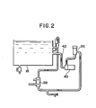
- Fig. 2 is a diagram showing the piping of the circulating device used in the present invention;
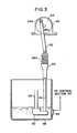
- Fig. 3 is a schematic view showing the diagrammatic construction of the bellows pump used in the present invention;
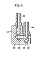
- Fig. 4 is a cross-sectional view showing the developer sucking portion incorporated in the automatic developing machine according to the present invention;
- Fig. 5 is a front elevational view of a meter and its periphery in the present invention;
- Fig. 6 is a flow chart showing a first method of detecting the remaining quantity of replenishing solution in accordance with the present invention; and
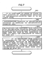
- Fig. 7 is a flow chart showing a second method of detecting the remaining quantity of replenishing solution in accordance with the present invention.
-
- A preferred embodiment of the present invention will be described in detail below with reference to the accompanying drawings. Fig. 1 shows an automatic developing
machine 10 according to the embodiment of the present invention. - The automatic developing
machine 10 according to the presently preferred embodiment is provided with the functions of developing, fixing, washing and drying an unprocessed film. - The outer wall of the automatic developing
machine 10 is constituted by abox 12, and a film insertion table 14 for allowing insertion of unprocessed films is disposed at an upper portion of the front of thebox 12, with afilm stocker 16 for storing processed films being disposed at an upper portion of the rear of thebox 12. A film sensor 80 for detecting the passage of films is mounted in the vicinity of an insertion opening which is formed, for insertion of an unprocessed film, in the portion of thebox 12 on which the film insertion table 14 is mounted. - The film sensor 80 includes a plurality of light emitting elements for emitting infrared rays outside of the region of sensitizing wavelengths which can cause photographic sensitization, and the light emitting elements are arranged in opposition to and parallel to the widthwise direction of a film. Corresponding light receiving elements are each turned on and off in accordance with the width of an inserted film and output a signal based on this width. The film sensor 80 may be of a type which is tuned on and off when the light receiving elements have received the light of the light emitting elements reflected from a film which has been inserted. Otherwise, the film sensor 80 may be constituted by a mechanical sensor.
- In the interior of the
box 12, a developingtank 18, afixing tank 20, awashing tank 22 and adrying section 24 are arranged in this order. Thebox 12 further includes a solution supplying device 28, asolution circulating device 30 and acontrol section 34. - The developing
tank 18, thefixing tank 20, thewashing tank 22 and thedrying section 24 are arranged in the order of film processing and respectively include a plurality ofguide rollers guide rollers - As shown in detail in Fig. 2, the
solution circulating device 30 disposed in the interior of thebox 12 includes adeveloper filter 36, aheat exchanger 38 and a circulatingpump 40. Apipe 42 provides communication between the circulatingpump 40 and the developingtank 18, and thedeveloper filter 36 communicates with the developingtank 18 through theheat exchanger 38. - As shown in Fig. 3, the solution supplying device 28 includes a replenishing-
solution tank 45 for storing a replenishing solution, abellows pump 46, and amotor 48. A lower-level sensor 49 for detecting the lower level of the replenishing solution is attached to the replenishing-solution tank 45. The lower-level sensor 49 is adapted to supply a signal to thecontrol section 34 when the replenishing solution has decreased to the lower level in the replenishing-solution tank 45. Analarm 53 is connected to thecontrol section 34 through adrive circuit 51 and, in response to the signal, thecontrol section 34 operates thealarm 53 to generate an alarm sound. The lower level is preferably selected so that at least the replenishing-solution tank 45 will not empty during the time that an operator who has noted the alarm sound takes to prepare a predetermined quantity of replenishing solution and to supply it to the replenishing-solution tank 45. - A predetermined quantity of replenishing solution is initially supplied to a level above the lower level in the replenishing-
solution tank 45, and a level corresponding to a quantity P of replenishing solution thus stored (the value obtained when the aforesaid predetermined quantity is added to the quantity of replenishing solution corresponding to the lower level) is determined as an upper level which is stored in thecontrol section 34. The quantity of replenishing solution that corresponds to the upper level is hereinafter referred to as a "storage quantity". - A bellows 46A is interlockingly connected at one end thereof to one end of a connecting
rod 52 which constitutes a clank mechanism. The other end of thebellows 46A is connected by apipe 64 to a replenishing-solution sucking portion 50 in the replenishing solution charged in the replenishing-solution tank 45. The other end of the connectingrod 52 is rotatably supported by aneccentric shaft 54A which is fixed at a position offset from the center of arotating disk 54 mounted to theoutput shaft 48A of themotor 48. - As shown in Fig. 4,
check valve members solution sucking portion 50 which is disposed in the replenishing solution charged in the replenishing-solution tank 45. Thecheck valve member 58 is arranged to open and close asuction port 62, and thecheck valve member 60 is arranged to open and close achannel 68 which provides communication between thepipe 64 and thepipe 66. - As shown in Fig. 1, the
control section 34 is constituted including aCPU 78, aninput port 70, anoutput port 72, aROM 74, and aRAM 76. The film sensor 80 and the lower-level sensor 40 are connected to theinput port 70, and theoutput port 72 is connected to thealarm 53 through adrive circuit 79 and to themotor 48 for driving the bellows pump 46 to supply the replenishing solution. Ameter 81 is connected to theoutput port 72 through thedrive circuit 79. - Referring to Fig. 5, the
meter 81 is provided with a liquid crystal display (LCD) 81A for providing a liquid crystal indication representing a quantity R of replenishing solution remaining in the replenishing-solution tank 45. Thealarm 53 mentioned previously is attached to a portion of the casing of themeter 81. The quantity R of replenishing solution remaining is calculated at predetermined time intervals by theCPU 78. More specifically, theROM 74 previously stores in table form the quantities of developer used that correspond to the areas S of film processed. The quantity of replenishing solution supplied to the developingtank 18 is equal to the quantity of replenishing solution used. Accordingly, the quantity R of replenishing solution remaining can be obtained by subtracting a quantity F representing the amount of replenishing solution supplied to the developingtank 18 in correspondence with the area S of film processed by the automatic developingmachine 10 for a predetermined period from the quantity (or upper level) P representing the amount of replenishing solution initially supplied to the replenishing-solution tank 45:
R = P - F (1) - If it is desired to supply the replenishing solution to the replenishing-
solution tank 45 during the operation of the automatic developingmachine 10, the remaining quantity R can be obtained by subtracting a quantity F′ representing the amount of replenishing solution supplied to the developingtank 18 in correspondence with an area S′ of film processed from the time of the actuation of thealarm 53 until the completion of supply of the replenishing solution from the quantity (or upper level) P representing the amount of replenishing solution initially supplied to the replenishing-solution tank 45:
R = P - F′(1)′ - The areas S and S′ of film processed can be readily obtained by multiplying a width W of film detected by the film sensor 80 by a film feed speed V previously stored in the ROM 74:
F = S x V (2),
F, = S x V (2)′ - The operation of the presently preferred embodiment will be described below.
- Electric power is supplied to the automatic developing
machine 10 and an unprocessed film is inserted from the film insertion table 14. When the unprocessed film passes the area below the film sensor 80, the film sensor 80 detects the passage of the film and inputs a detection signal to the input port of thecontrol section 34. - When passed the area below the film sensor 80, the unprocessed film is fed along the film feed passage formed by the
guide rollers 18A arranged in the developingtank 18, and is guided to the bottom portion of the developingtank 18. The thus-guided film is reversed by theguide rollers 18A arranged in the bottom portion and fed to the top portion of the developingtank 18. In this manner, the unprocessed film is passed through the developer for a predetermined period of time, and is thus developed. - The film developed is further guided to the fixing
tank 20 by the plurality ofguide rollers 20A, and is fixed in the fixingtank 20. Then, the fixed film is washed while it passing through the film feed passage formed by the plurality ofguide rollers 22A arranged in thewashing tank 22. The washed film passes through the dryingsection 24 while being guided by theguide rollers 24A, and drying of the film is effected in thedrying section 24. The film thus dried is stored in thefilm stocker 16. - The developing
tank 18 is periodically supplied with the replenishing solution from the replenishing-solution tank 45. The replenishing solution is supplied in accordance with the quantity of film processed (the area S of film processed). More specifically, when the width W of the unprocessed film which has been obtained by the film sensor 80 is supplied to thecontrol section 34, theCPU 78 reads out the film feed speed V stored in theROM 74 and calculates the area S of film processed (W x V). The quantity of developer used in correspondence with the area S is selected from the data which is stored in theROM 74 in table form. Themotor 48 is driven to actuate the bellows pump 46A, thereby supplying the selected quantity of replenishing solution. Thus, the developingtank 18 is charged with an optimum quantity of developer. - If the above-described supply is repeated, the quantity of replenishing solution will decrease in the replenishing-
solution tank 45 until the quantity of replenishing solution in the replenishing-solution tank 45 will reach the lower level. When the lower-level sensor 49 detects the fact that the quantity of replenishing solution has reached the lower level, theCPU 78 causes thealarm 53 to generate an alarm sound. Thus, the operator prepares a predetermined quantity of replenishing solution and supplies it to the replenishing-solution tank 45. Therefore, the replenishing-solution tank 45 is prevented from emptying. - In the present embodiment, it is also possible to detect the quantity of replenishing solution remaining in the replenishing-
solution tank 45 and indicate the detection quantity by means of themeter 81. Methods of effecting the detection will be described with reference to the flow charts shown in Figs. 6 and 7. - A first method will be described with reference to Fig. 6.
- First, prior to operating the automatic developing
machine 10, the quantity of replenishing solution then stored in the replenishing-solution tank 45 is set as the lower level. InStep 100, a predetermined quantity of replenishing solution is suppled in this state, and the resultant quantity P of replenishing solution stored in the replenishing-solution tank 45 is set as the upper level and is stored in theRAM 76 of thecontrol section 34. - In this state, the automatic developing
machine 10 is operated inStep 102. InStep 104, the width W of the film is supplied to thecontrol section 34, and the quantity F of replenishing solution supplied is calculated from the above equation (2). InStep 106, the quantity F of replenishing solution calculated is subtracted from the quantity P of replenishing solution stored in the replenishing-solution tank 45 (P - F). - A second detection method will be described below with reference to Fig. 7.
- When it has been confirmed in
Step 200 by the alarm sound generated by thealarm 53 that the quantity of replenishing solution in the replenishing-solution tank 45 has reached the lower level, the process proceeds to Step 202. InStep 202, a predetermined quantity of replenishing solution is supplied to the replenishing-solution tank 45 which is in the state described above. During this time, since the automatic developingmachine 10 is operating, the quantity of replenishing solution in the replenishing-solution tank 45 decreases, by the quantity F′ of supply which is calculated from the above equation (2′), by the time that the supply of the replenishing solution to the replenishing-solution tank 45 has been completed. The quantity F′ of supply is subtracted from the quantity P of replenishing solution initially supplied to the replenishing-solution tank 45 which quantity P is previously stored in the RAM 76 (P - F′). Since the result of these calculations (the remaining quantity R) is indicated by themeter 81, it is possible to visually confirm the quantity of replenishing solution remaining in the replenishing-solution tank 54 without the need to directly view the replenishing-solution tank 45. Furthermore, the readings indicative of the remaining quantity do not include any error since they are calculated employing an equation identical with the equation used for calculating the quantity of replenishing solution supplied to the developing tank by the driving of the bellows pump 46. If account is taken of the quantity of supply so as to compensate for the deterioration of the solution due to air, further accurate results can be obtained. - As described above, in the presently preferred embodiment, the remaining quantity of replenishing solution is calculated from the result obtained from the quantity of film processed. Therefore, it is unnecessary that cuts representative of a scale be formed in the replenishing-
solution tank 45 made of a transparent or translucent material, and hence the production cost of the replenishing-solution tank 45 can be reduced. In addition, since there is no risk that an operator may misidentify the remaining quantity because of his misreading of a liquid level due to the contaminated scale of the replenishing-solution tank 45, the operability of the replenishing-solution tank 45 is improved. Moreover, since it is unnecessary to expose any portion (the scale) of the replenishing-solution tank 45 to the outside of the automatic developingmachine 10, the freedom of design in the layout of the replenishing-solution tank 45 widens and this enables the automatic developingmachine 10 itself to be made compact. - In the present embodiment, the
meter 81 for displaying the remaining quantity of replenishing solution is constituted by a so-called digital display meter which displays figures themselves in liquid crystal form. However, it is possible to use any other type of meter, for example, a so-called analog display meter in which an indicating needle moves over an equally graduated plate. - The
digital meter 81 used in the present embodiment is arranged to display the remaining quantity of replenishing solution at any time. However, as shown by an imaginary line in Fig. 5, anoperation button 83 may be disposed at an arbitrary location around themeter 81 so that the remaining quantity may be displayed by operating theoperation button 83 only when required. - By way of example, the description of the present embodiment refers to a method of displaying the remaining quantity of replenishing solution. However, if a replenishing-solution tank for another replenishing solution (for example, a fixing solution) is incorporated in the automatic developing
machine 10, the present invention can also be applied to such a replenishing-solution tank. - In the present embodiment, the quantity of replenishing solution in the replenishing-
solution tank 45 is detected as the lower level by the lower-level sensor 49 and a predetermined quantity of replenishing solution is added to the replenishing solution of this lower level, and the quantity of replenishing solution then supplied is stored as the upper level. However, an upper-level graduation may also be formed on the replenishing-solution tank 45 and the replenishing solution may be supplied to the position of the upper-level graduation. Since this graduation indicates the upper-level position, there is no risk that an operator may misread this graduation. - Moreover, the displaying of the remaining quantity of replenishing solution may be started when the
alarm 53 starts up in response to the signal of the lower-level sensor 49. - In the present embodiment, the remaining quantity is displayed as the quantity of replenishing solution actually remaining in the replenishing-
solution tank 45. Furthermore, the lower level may be set to a zero quantity, and the quantity below the lower level may be displayed as minus values.
Claims (10)
Applications Claiming Priority (4)
| Application Number | Priority Date | Filing Date | Title |
|---|---|---|---|
| JP150399/87 | 1987-06-17 | ||
| JP150402/87 | 1987-06-17 | ||
| JP15040287A JPH0636095B2 (en) | 1987-06-17 | 1987-06-17 | How to display the remaining amount of replenisher |
| JP15039987A JPS63314416A (en) | 1987-06-17 | 1987-06-17 | Residue display for replenisher |
Publications (3)
| Publication Number | Publication Date |
|---|---|
| EP0295663A2 true EP0295663A2 (en) | 1988-12-21 |
| EP0295663A3 EP0295663A3 (en) | 1992-02-26 |
| EP0295663B1 EP0295663B1 (en) | 1994-09-07 |
Family
ID=26480003
Family Applications (1)
| Application Number | Title | Priority Date | Filing Date |
|---|---|---|---|
| EP88109571A Expired - Lifetime EP0295663B1 (en) | 1987-06-17 | 1988-06-15 | Method of detecting remaining quantity of replenishing solution |
Country Status (3)
| Country | Link |
|---|---|
| US (1) | US4858468A (en) |
| EP (1) | EP0295663B1 (en) |
| DE (1) | DE3851373T2 (en) |
Families Citing this family (5)
| Publication number | Priority date | Publication date | Assignee | Title |
|---|---|---|---|---|
| US5847984A (en) * | 1997-07-17 | 1998-12-08 | Advanced Micro Devices, Inc. | Combination propagate and generate carry lookahead gate |
| US5908140A (en) * | 1997-08-21 | 1999-06-01 | Technical Concepts, L.P. | Material dispensing method and apparatus with stall detect |
| US5884808A (en) * | 1997-08-21 | 1999-03-23 | Technical Concepts, L.P. | Material dispensing method and apparatus having display feature |
| JP2009074874A (en) * | 2007-09-19 | 2009-04-09 | Sysmex Corp | Liquid suction device for analyzing specimen and specimen analyzer |
| CN103110340B (en) * | 2013-02-28 | 2015-07-22 | 许锦标 | Automatic flavoring device suitable for full-automatic cooker |
Citations (3)
| Publication number | Priority date | Publication date | Assignee | Title |
|---|---|---|---|---|
| DE3326719A1 (en) * | 1982-07-26 | 1984-01-26 | Jaeger, 92303 Levallois-Perret, Hauts-de-Seine | METHOD AND DEVICE FOR MEASURING THE QUANTITY OF LIQUID CONTAINED IN A TANK |
| EP0165802A2 (en) * | 1984-06-18 | 1985-12-27 | Xerox Corporation | Method and apparatus for monitoring and maintaining concentrate material in a fluid carrier |
| US4577950A (en) * | 1984-07-13 | 1986-03-25 | Mackson Richard G | Computer controlled replenishing system for automatic film processor |
Family Cites Families (8)
| Publication number | Priority date | Publication date | Assignee | Title |
|---|---|---|---|---|
| US3377859A (en) * | 1965-12-23 | 1968-04-16 | Westinghouse Air Brake Co | Means for measuring change in reservoir fluid level |
| BE794254A (en) * | 1972-01-22 | 1973-05-16 | Fur Pat Fab | METHOD AND DEVICE FOR MEASURING THE GAP BETWEEN A LOCALLY FIXED PART AND A MOBILE PART |
| US4339950A (en) * | 1980-02-19 | 1982-07-20 | Lendino Nicholas C | Counting mechanism attachment for a fuel tank |
| JPS57172245A (en) * | 1981-03-24 | 1982-10-23 | Copyer Co Ltd | Toner concentration controlling circuit of electronic copier |
| JPS57201664A (en) * | 1981-06-08 | 1982-12-10 | Canon Inc | Ink residual quantity detector |
| JPS5853724A (en) * | 1981-09-28 | 1983-03-30 | Mitsubishi Electric Corp | Automatic measuring device in sucking type fecal tank lorry |
| JPS58209648A (en) * | 1982-06-01 | 1983-12-06 | Nissan Motor Co Ltd | Reservoir fitted with liquid level detector |
| JPS60185134A (en) * | 1985-01-19 | 1985-09-20 | Olympus Optical Co Ltd | Apparatus for detecting remaining quantity of liquid |
-
1988
- 1988-06-13 US US07/205,699 patent/US4858468A/en not_active Expired - Lifetime
- 1988-06-15 EP EP88109571A patent/EP0295663B1/en not_active Expired - Lifetime
- 1988-06-15 DE DE3851373T patent/DE3851373T2/en not_active Expired - Fee Related
Patent Citations (3)
| Publication number | Priority date | Publication date | Assignee | Title |
|---|---|---|---|---|
| DE3326719A1 (en) * | 1982-07-26 | 1984-01-26 | Jaeger, 92303 Levallois-Perret, Hauts-de-Seine | METHOD AND DEVICE FOR MEASURING THE QUANTITY OF LIQUID CONTAINED IN A TANK |
| EP0165802A2 (en) * | 1984-06-18 | 1985-12-27 | Xerox Corporation | Method and apparatus for monitoring and maintaining concentrate material in a fluid carrier |
| US4577950A (en) * | 1984-07-13 | 1986-03-25 | Mackson Richard G | Computer controlled replenishing system for automatic film processor |
Also Published As
| Publication number | Publication date |
|---|---|
| DE3851373T2 (en) | 1995-01-19 |
| DE3851373D1 (en) | 1994-10-13 |
| US4858468A (en) | 1989-08-22 |
| EP0295663B1 (en) | 1994-09-07 |
| EP0295663A3 (en) | 1992-02-26 |
Similar Documents
| Publication | Publication Date | Title |
|---|---|---|
| US3990088A (en) | System for controlling replenishment of developer solution in a photographic processing device | |
| US5511408A (en) | Automatic calibrating apparatus for laboratory ion concentration meter | |
| JPS6350650B2 (en) | ||
| JPH0723895B2 (en) | Method for controlling reagent amount of automatic analyzer | |
| EP0295663B1 (en) | Method of detecting remaining quantity of replenishing solution | |
| US3696728A (en) | Film processor | |
| US4314753A (en) | Automatic inverse fix replenisher control | |
| US4466072A (en) | Automatic fixed-quantity/fixed-time anti-oxidation replenisher control system | |
| EP0623842B1 (en) | Photographic processing apparatus | |
| JP3681234B2 (en) | Liquid remaining amount detection device for liquid containers | |
| US4372665A (en) | Automatic variable-quantity/fixed-time anti-oxidation replenisher control system | |
| EP0683431A1 (en) | Automatic developing apparatus for developing a photosensitive material | |
| EP0241858B1 (en) | Method of supplying replenishing solution in automatic developing machine | |
| EP0456167B1 (en) | Apparatus for treating a photosensitive material and method of adding water for use in the same | |
| EP0442221A2 (en) | Automatic photo processor | |
| JPS63314416A (en) | Residue display for replenisher | |
| JP3688790B2 (en) | Automatic processor | |
| JPS63314417A (en) | Residue display for replenisher | |
| JP2692714B2 (en) | Replenisher replenisher for automatic processor | |
| JP3662317B2 (en) | Solution replenishment method for photosensitive material processing apparatus and photosensitive material processing apparatus | |
| EP0809148A1 (en) | Photographic developing apparatus and method of supplying water to the apparatus | |
| JPH049055A (en) | Processing device for photosensitive material and hydrating method for this device | |
| US5189456A (en) | Method and apparatus for adjusting the volume of replenishment fluid provided to a chamber of a film processor | |
| EP0582752A1 (en) | Photographic development apparatus and a method relating thereto | |
| JPS61275757A (en) | Replenishing solution controlling device for automatic developing device |
Legal Events
| Date | Code | Title | Description |
|---|---|---|---|
| PUAI | Public reference made under article 153(3) epc to a published international application that has entered the european phase |
Free format text: ORIGINAL CODE: 0009012 |
|
| AK | Designated contracting states |
Kind code of ref document: A2 Designated state(s): DE FR GB |
|
| PUAL | Search report despatched |
Free format text: ORIGINAL CODE: 0009013 |
|
| AK | Designated contracting states |
Kind code of ref document: A3 Designated state(s): DE FR GB |
|
| 17P | Request for examination filed |
Effective date: 19920824 |
|
| 17Q | First examination report despatched |
Effective date: 19931103 |
|
| GRAA | (expected) grant |
Free format text: ORIGINAL CODE: 0009210 |
|
| AK | Designated contracting states |
Kind code of ref document: B1 Designated state(s): DE FR GB |
|
| REF | Corresponds to: |
Ref document number: 3851373 Country of ref document: DE Date of ref document: 19941013 |
|
| ET | Fr: translation filed | ||
| PLBE | No opposition filed within time limit |
Free format text: ORIGINAL CODE: 0009261 |
|
| STAA | Information on the status of an ep patent application or granted ep patent |
Free format text: STATUS: NO OPPOSITION FILED WITHIN TIME LIMIT |
|
| 26N | No opposition filed | ||
| REG | Reference to a national code |
Ref country code: GB Ref legal event code: IF02 |
|
| PGFP | Annual fee paid to national office [announced via postgrant information from national office to epo] |
Ref country code: FR Payment date: 20040504 Year of fee payment: 17 |
|
| PGFP | Annual fee paid to national office [announced via postgrant information from national office to epo] |
Ref country code: GB Payment date: 20040607 Year of fee payment: 17 |
|
| PGFP | Annual fee paid to national office [announced via postgrant information from national office to epo] |
Ref country code: DE Payment date: 20040730 Year of fee payment: 17 |
|
| PG25 | Lapsed in a contracting state [announced via postgrant information from national office to epo] |
Ref country code: GB Free format text: LAPSE BECAUSE OF NON-PAYMENT OF DUE FEES Effective date: 20050615 |
|
| PG25 | Lapsed in a contracting state [announced via postgrant information from national office to epo] |
Ref country code: DE Free format text: LAPSE BECAUSE OF NON-PAYMENT OF DUE FEES Effective date: 20060103 |
|
| PG25 | Lapsed in a contracting state [announced via postgrant information from national office to epo] |
Ref country code: FR Free format text: LAPSE BECAUSE OF NON-PAYMENT OF DUE FEES Effective date: 20060228 |
|
| GBPC | Gb: european patent ceased through non-payment of renewal fee |
Effective date: 20050615 |
|
| REG | Reference to a national code |
Ref country code: FR Ref legal event code: ST Effective date: 20060228 |