EP0295491B1 - Apparatus for and method of stabilizing the quantity of light of fluorescent lamp - Google Patents
Apparatus for and method of stabilizing the quantity of light of fluorescent lamp Download PDFInfo
- Publication number
- EP0295491B1 EP0295491B1 EP88108716A EP88108716A EP0295491B1 EP 0295491 B1 EP0295491 B1 EP 0295491B1 EP 88108716 A EP88108716 A EP 88108716A EP 88108716 A EP88108716 A EP 88108716A EP 0295491 B1 EP0295491 B1 EP 0295491B1
- Authority
- EP
- European Patent Office
- Prior art keywords
- fluorescent lamp
- tube current
- control signal
- current control
- light quantity
- Prior art date
- Legal status (The legal status is an assumption and is not a legal conclusion. Google has not performed a legal analysis and makes no representation as to the accuracy of the status listed.)
- Expired - Lifetime
Links
Images


Classifications
-
- H—ELECTRICITY
- H05—ELECTRIC TECHNIQUES NOT OTHERWISE PROVIDED FOR
- H05B—ELECTRIC HEATING; ELECTRIC LIGHT SOURCES NOT OTHERWISE PROVIDED FOR; CIRCUIT ARRANGEMENTS FOR ELECTRIC LIGHT SOURCES, IN GENERAL
- H05B41/00—Circuit arrangements or apparatus for igniting or operating discharge lamps
- H05B41/14—Circuit arrangements
- H05B41/36—Controlling
- H05B41/38—Controlling the intensity of light
- H05B41/39—Controlling the intensity of light continuously
- H05B41/392—Controlling the intensity of light continuously using semiconductor devices, e.g. thyristor
- H05B41/3921—Controlling the intensity of light continuously using semiconductor devices, e.g. thyristor with possibility of light intensity variations
- H05B41/3922—Controlling the intensity of light continuously using semiconductor devices, e.g. thyristor with possibility of light intensity variations and measurement of the incident light
-
- G—PHYSICS
- G03—PHOTOGRAPHY; CINEMATOGRAPHY; ANALOGOUS TECHNIQUES USING WAVES OTHER THAN OPTICAL WAVES; ELECTROGRAPHY; HOLOGRAPHY
- G03G—ELECTROGRAPHY; ELECTROPHOTOGRAPHY; MAGNETOGRAPHY
- G03G15/00—Apparatus for electrographic processes using a charge pattern
- G03G15/04—Apparatus for electrographic processes using a charge pattern for exposing, i.e. imagewise exposure by optically projecting the original image on a photoconductive recording material
- G03G15/04036—Details of illuminating systems, e.g. lamps, reflectors
-
- H—ELECTRICITY
- H01—ELECTRIC ELEMENTS
- H01J—ELECTRIC DISCHARGE TUBES OR DISCHARGE LAMPS
- H01J61/00—Gas-discharge or vapour-discharge lamps
- H01J61/02—Details
- H01J61/52—Cooling arrangements; Heating arrangements; Means for circulating gas or vapour within the discharge space
Definitions
- the present invention relates to an apparatus and a method, respectively, for stabilizing the light output of a fluorescent lamp according to the pre-characterizing clause of claims 1 and 11, respectively (JP-A-60-186828).
- the present invention relates to an apparatus for stabilizing the light output of a fluorescent lamp employed for illuminating an original picture in a system of duplicating pictures through an optical system by a photoengraving process, for example, and a method of stabilizing the light output thereof.
- a fluorescent lamp which is generally employed as an illumination source, is also applicable in the field of printing to a color separation process for a color original picture, for example, as a cold light source having relative spectral distribution substantially equal to spectral luminous efficacy and small calorific power.
- a fluorescent lamp is preferably applied to an image reader employing a recently developed semiconductor optical sensor such as a CCD, since a light source such as a halogen lamp containing a large quantity of infrared rays in its spectral characteristic degrades the quality of a duplicated picture image.
- a fluorescent lamp causes a problem in the context of a photoengraving process for scanning an original sequentially along lines to read image density information thereof in high density, since errors are caused in read data thereof if the quantity of light for illuminating the original fluctuates in the scanning interval. Therefore, employed in this field is a light source such as a halogen lamp, the light output of which fluctuates less.
- a copying machine or the like generally requires a short time of about 1 sec. for reading an original including that of the maximum size (A3: 297 mm x 420 mm), and hence change in the quantity of light in such a short time can be neglected.
- A3: 297 mm x 420 mm the maximum size
- change in the quantity of light in such a short time can be neglected.
- employment of a fluorescent light source causes no problem in practice, in the case of a copying machine etc.
- a scanner such as a facsimile also employs a fluorescent lamp as a light source. This is because an image is generally bilevellized in black and white with no intermediate density in the case of the facsimile and slight change in the quantity of light causes substantially no problem.
- the light output of a fluorescent lamp is decided by mercury vapor pressure in the fluorescent lamp and the tube current thereof.
- the mercury vapor pressure depends on the ambient temperature thereof, which also decides luminous efficiency.
- the lowest point (hereinafter referred to as "coldest point") of the tube wall temperature of the fluorescent lamp decides the mercury vapor pressure as well as the luminous efficiency of the fluorescent lamp. Therefore, the luminous efficiency of the fluorescent lamp can be controlled by providing the coldest point in some portion on the tube wall of the fluorescent lamp and controlling the temperature thereof.
- the light output of the fluorescent lamp can be stabilized by appropriately controlling its tube current.
- an exposure lamp controller in which a fluorescent lamp is controlled using respective detecting means for detecting the light output of said fluorescent lamp as well as feedback means for controlling the tube current of said fluorescent lamp for making the light quantity value output by said fluorescent lamp constant.
- Fig. 1 shows another apparatus which has been proposed in the art to stabilize the light output of a fluorescent lamp and distribution thereof.
- light emitted directly from a fluorescent lamp 1 and light reflected from an original is received by an optical sensor 2 for monitoring the light output, and an output from the optical sensor 2 is input to a light quantity feedback unit 4 through an amplifier 3.
- An output (tube current control signal) from the light quantity feedback unit 4 is supplied to a fluorescent lamp inverter 5, which in turn supplies appropriate tube current to the fluorescent lamp 1 in response to the tube current control signal.
- the light quantity feedback unit 4 is adapted to control the fluorescent lamp inverter 5 in response to the level of the signal from the optical sensor 2 for adjusting the tube current to be fed to the fluorescent lamp 1, thereby to regularly maintain the output level of the optical sensor 2 at a constant value.
- a cooling device 6 such as a Peltier device is brought into contact with a prescribed tube wall portion of the fluorescent lamp 1, in order to control the position and the temperature of the coldest point of the fluorescent lamp 1.
- a temperature sensor 7 such as a thermistor is interposed between the cooling device 6 and the tube wall.
- the cooling device 6 is controlled by a cooling device driver 8 in response to a value detected by the temperature sensor 7, so that the temperature of the coldest point is maintained at a desired value.
- heaters 9 are serially provided at regular intervals on the tube wall of the fluorescent lamp 1 except for the portion which is in contact with the cooling device 6.
- a temperature sensor 10 such as a thermistor is provided in an appropriate portion of the tube wall of the fluorescent lamp 1.
- the heaters 9 are controlled by temperature control means (not shown) in response to a value detected by the temperature sensor 10, to heat the part of the tube wall of the fluorescent lamp 1 in contact with the heaters 9 up to a prescribed temperature exceeding that of the coldest point.
- the desired effect of stabilizing the light output can be attained with the optical sensor 2 receiving only the light from the fluorescent lamp 1. If the apparatus is applied to an image scanner, however, an error may be caused since the optical sensor 2 receives light reflected by the surface of an original to be duplicated in addition to the light directly received from the fluorescent lamp 1.
- the quantity of light received by the optical sensor 2 is reduced in scanning a high-density region (dark part) of the original as compared with that in scanning a low-density region (bright part), whereby the light quantity feedback unit 4 controls the fluorescent lamp inverter 5 to increase the tube current of the fluorescent lamp 1, similarly to the case where the quantity of light of the fluorescent lamp 1 is reduced.
- the light quantity feedback unit 4 controls the fluorescent lamp inverter 5 to reduce the tube current of the fluorescent lamp 1.
- a principal object of the present invention is to provide an apparatus for and a method of stabilizing the light output of a fluorescent lamp, which can stably maintain the light output of the fluorescent lamp for a prescribed period of time required for scanning an original, without being influenced by variable density of the original to be duplicated.
- Fig. 2 schematically illustrates an exemplary original scanner to which the present invention is applied.
- a white reference panel 11 and an original 12 to be duplicated are mounted on an original table (not shown), to be fed in the direction of arrow 13 by appropriate driving means.
- the light is reflected by the white reference panel 11 or the original 12 to be duplicated and its direction is changed by a mirror 14, to be projected on a photoelectric element 16 such as a CCD through a lens 15, for image formation.
- the photoelectric element 16 outputs an image signal of the original 12 to be duplicated.
- the present invention is particularly applicable to a method of and an apparatus for stabilizing the light output of the fluorescent lamp 1 in such a scanner or the like.
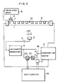
- Fig. 3 is a block diagram showing a first embodiment of the present invention.
- the apparatus is different from the conventional apparatus shown in Fig. 1 in that a switch driver 17, a switch 18, a host computer 19, an A-D converter 20 and a D-A converter 21 are additionally provided.
- An output side of a light quantity feedback unit 4 is connected to an "a" contact side of the switch 18, opening/closing of which is controlled by the switch driver 17.
- the switch driver 17 is controlled by the host computer 19.
- the output side of the light quantity feedback unit 4 is also connected to a "b" contact side of the switch 18 through the A-D converter 20 and the D-A converter 21, and the A-D converter 20 is also controlled by the host computer 19.
- the reference density image is scanned to obtain a suitable tube current control value (step (B)) as well as to hold the value (step (C)), while the tube current of the fluorescent lamp 1 is controlled on the basis of this value when scanning the original to be duplicated, whereby the light output and light distribution of the fluorescent lamp 1 can be stabilized with no influence being exerted by the density of the original to be duplicated.
- the output value of the light quantity feedback unit 4, i.e., the tube current control signal for commanding increase/decrease of the tube current to the fluorescent lamp inverter 5 on the basis of change in the light output of the fluorescent lamp 1, is converted to the digital value thereof by the A-D converter 20 to be transferred to the host computer 19 for display, whereby the time for exchanging the fluorescent lamp 1 can be recognized.
- the tube current of the fluorescent lamp 1 must be increased in order to obtain a constant quantity of light thereof in the last stage of its lifetime.
- the value of the tube current control signal transferred to the host computer 19 is so digitally displayed on display means at the step (C) that the time for exchanging the fluorescent lamp 1 can be extremely precisely recognized when the value exceeds a certain level.
- the converted digital value does not directly indicate the tube current value but the converted digital value of "100” is for the tube current value of "200mA”, and the former of "1000” is for the latter of "400 mA", for example.
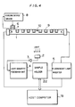
- Fig. 4 is a block diagram showing a second embodiment of the present invention.
- the apparatus shown in Fig. 4 is provided with a sample holder 22 in place of the switch driver 17, the switch 18, the A-D converter 20 and the D-A converter 21 of the first embodiment shown in Fig. 3.
- Other structure of the second embodiment is similar to that of the first embodiment.
- the sample holder 22 is selectively switched by a mode switching signal supplied from host computer 19 to a first mode for passing a tube current control signal output from light quantity feedback unit 4 and a second mode for holding the tube current control signal.
- the sample holder 22 must be such as to have a small droop rate, i.e., there must be no or substantially no change with time in the tube current control signal held in the same.
- the tube current supplied to the fluorescent lamp 1 during scanning of the original has a constant value corresponding to the value of the tube current control signal held in the sample holder 22 at the step (C) similarly to the first embodiment, whereby the light output and light distribution of the fluorescent lamp 1 can be stabilized if the position and temperature of the coldest point are constantly held.
- a line sensor such as a CCD for picking up an image signal in line-sequential scanning on an original is also applied to stabilize/control the light output of the fluorescent lamp.
- Fig. 5 is a perspective view schematically showing the third embodiment.
- a cooling device 6 As shown in Fig. 5, a cooling device 6, a temperature sensor 7 and heaters (not shown) are provided on the tube wall of a fluorescent lamp 1 to constantly hold the position and the temperature of the coldest point, similarly to the embodiments shown in Figs. 3 and 4.
- a scanned plane illuminated by the fluorescent lamp 1 is provided thereon with a white reference panel 11 serving as a reference density image in calibration and with an original 12 to be duplicated in duplication/scanning of an image, so that light reflected by the same is projected on a CCD line sensor 16 by a mirror 14 and a lens 15, for image formation.
- a douser (not shown) is provided on the fluorescent lamp 1, so that no light enters the lens 15, directly.
- An output signal from the CCD line sensor 16 is input to a host computer 19 thorugh an A-D converter 20, so that the host computer 19 outputs a tube current control value to a fluorescent lamp inverter 5 through a D-A converter 21 on the basis of the data.
- the tube current control value is constantly controlled by the host computer 19, whereby the light output and light distribution can be stabilized if the position and temperature of the coldest point are constantly maintained.
- the third embodiment requires no optical sensor since the light output of the fluorescent lamp 1 is detected by the line sensor 16 for scanning the image. Further, the host computer 19 is also adapted to perform feedback control, whereby the light quantity feedback unit, which is required in each of the first and second embodiments, can be omitted.
- the white reference panel 11 (shown in Fig. 2) is employed as a reference density image in each of the aforementioned embodiments, the reference density image is not restricted to the same.
- a gray reference panel may be employed as the reference density image, to obtain a tube current control value for stabilizing the quantity of light.
- Fig. 6 is a block diagram showing an apparatus according to a fourth embodiment of the present invention.
- a heater 24 is provided in contact with a substantially central tube wall portion of a fluorescent lamp 1 except for portions for extracting light from the fluorescent lamp 1, while a thermal conduction buffering member 23, being formed by a heat transfer layer 23a of aluminium etc. and a heat storage layer 23b of glass etc., is provided in contact with an end portion of the tube wall.
- a temperature sensor such as a thermistor is provided on the surface of the heater 24, so that the heater 24 is controlled by temperature control means (not shown) in response to a value detected by the temperature sensor to heat the tube wall of the fluorescent lamp 1 which is in contact with the heater 24 to a prescribed temperature exceeding that of the coldest point, thereby to maintain the tube wall of the fluorescent lamp 1 being in contact with the termal conduction buffering member 23 at a prescribed coldest point temperature.
- Other structure shown in Fig. 6 is similar to that of the apparatus according to the first embodiment.
- the heater 24 is provided entirely over the tube wall of the fluorescent lamp 1 except for the region provided with the thermal conduction buffering member 23 in order to reliably bring the portion provided with the thermal conduction buffering member 23 into the coldest temperature, the same may be replaced by a plurality of heaters which are serially provided at appropriate regularly spaced locations similarly to the first to third embodiments, as a matter of course.
- the heat transfer layer 23a is so connected that one surface thereof is in contact with the tube wall of the fluorescent lamp 1 and the other surface thereof is overlapped with the heat storage layer 23b.
- Silicon grease members (not shown) are interposed in contact surfaces between the heat transfer layer 23a and the fluorescent lamp 1 and between the heat transfer layer 23a and the heat storage layer 23b, respectively.
- Fig. 7 illustrates the structure of the fluorescent lamp 1 shown in Fig. 6 and Fig. 8 is a sectional view taken along the line A - A in Fig. 7, while Fig. 9 is a perspective view showing an end of the fluorescent lamp 1 shown in Fig. 7.
- Two such fluorescent lamps 1 are housed in a casing 25 of aluminium having a U-shaped sectional configuration in a parallel manner, to be fixed by holders 26 provided on both ends of the casing 25.
- Operation of the fourth embodiment is similar to that of the first embodiment shown in Fig. 3 except for a step (A), at which the temperature of the fluorescent lamp 1 is brought into an equilibrium state upon power supply.
- the heater 24 is started upon power supply.
- the heater 24 is so controlled by the temperature control means (not shown) that the surface temperature of the fluorescent lamp 1 measured by the temperature sensor reaches a constant level exceeding the coldest point temperature (48°C).
- the thermal conduction buffering member 23 is in contact with a part of the tube wall of the fluorescent lamp 1 to naturally release heat on the tube wall of the fluorescent lamp 1 to the exterior and cool the same, whereby the said tube wall part of the fluorescent lamp 1 being in contact with the thermal conduction buffering member 23 is cooled to a constant temperature which is lower than the tube wall temperature of the fluorescent lamp 1 in another portion, namely the temperature of the same is the coldest point one.
- Such control of the coldest point temperature is performed continuously during energization of the heater 24, i.e., from start to end of daily operation in general.
- the thermal conduction buffering member 23 for forming the coldest point of the fluorescent lamp 1 is provided with the heat storage layer 23b of low thermal conductivity.
- the ambient temperature of the thermal conduction buffering member 23 is abruptly changed by change in the room temperature etc. during an original scanning interval of about one to two minutes in general, for example, the coldest point of the tube wall of the fluorescent lamp 1 is hardly influenced by the ambient temperature, due to heat storage function of the heat storage layer 23b. Therefore, substantially no fluctuation is caused in the coldest point temperature during the original scanning interval in the aforementioned apparatus, whereby the fluorescent lamp 1 is prevented from changing its light output.
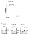
- Fig. 10 is a graph showing the result of a test for measuring actual change in the light output of the fluorescent lamp 1 when the same was turned on after its temperature was brought into an equilibrium state in the apparatus shown in Fig. 6.
- the horizontal axis indicates time elapsed upon lighting, and the vertical axis indicates illuminance at a substantially central portion of the fluorescent lamp 1.
- illuminance reached a certain value shortly after lighting of the fluorescent lamp 1, and then the value was lowered by about 0.5 to 1.0 % to be stabilized at a substantially constant level.
- a similar result was obtained whatever the room temperature was within a range of 10 to 40 (°C).
- the heat storage layer 23b is made of glass in the above embodiment, the same may alternatively be formed of another material having low thermal conductivity.
- Table 1 shows the coldest point temperatures actually measured with heat storage layers 23b of alumina, 18-8 stainless steel and polyethylene at the room temperatures of 10 (°C) and 40 (°C). Table 1 suggests that alumina, 18-8 stainless steel and polyethylene are also employable as materials for the heat storage layer 23b, to attain an effect similar to that of the heat storage layer 23b made of glass.
- control temperatures of the temperature sensor are set at levels higher by several degrees than the temperatures listed in Table 1, in order to ensure the coldest point temperature.
- the luminous efficiency of a fluorescent lamp is at the maximum when the coldest point temperature is about 40 (°C), and is lower in other cases.
- this value has been obtained under such condition that the fluorescent lamp was left in a constant temperature bath maintained at about 40 (°C) for two hours with no preheating means such as a heater, so that the quantity of initial light flux obtained upon lighting of this fluorescent lamp was at the maximum.
- the coldest point temperature is preferably maintained at about 40 (°C) under different condition such as that of continuous lighting.
- the position and temperature of the coldest point of the fluorescent lamp 1 are controlled by the cooling device 6, the temperature sensor 7 and the cooling device driver 8 shown in Fig. 4 or 5 in each of the second and third embodiments, such control may be performed by bringing a thermal conduction buffering member 23, which is formed by a heat transfer layer 23a of aluminium etc. and a heat storage layer 23b of glass etc., into contact with a prescribed position on the tube wall of a fluorescent lamp 1 similarly to the fourth embodiment.
- heaters 9 are serially provided at appropriately spaced locations on a tube wall region of the fluorescent lamp 1 other than a region being in contact with the thermal conduction buffering member 23 similarly to the second or third embodiment, in order to reliably bring the portion provided with the thermal conduction buffering member 23 into the coldest point.
- a heater may alternatively be provided entirely over such a region, similarly to the fourth embodiment.
- a thermal conduction buffering member 23 may be formed only by a heat storage layer 23b shown in Fig. 11.
- a thermal conduction buffering member 23 may be formed by a heat radiation layer 23c of a material having high thermal conductivity such as aluminium and a heat storage layer 23b shown in Fig. 12, with the heat storage layer 23b being in contact with the tube wall of a fluorescent lamp 1.
- a heat transfer layer 23a and a heat radiation layer 23c may be overlapped on both sides of a heat storage layer 23b to form a thermal conduction buffering member 23 shown in Fig. 13, with the heat transfer layer 23a being brought into contact with the tube wall of a fluorescent lamp 1.
- a thermal conduction buffering member 23 shown in Fig. 13 With the heat transfer layer 23a being brought into contact with the tube wall of a fluorescent lamp 1.
- the present invention is not restricted to this but applicable to a purely optical scanner, which projects an original image on a photosensitive material surface through an image forming lens.
Description
- The present invention relates to an apparatus and a method, respectively, for stabilizing the light output of a fluorescent lamp according to the pre-characterizing clause of
claims - The present invention relates to an apparatus for stabilizing the light output of a fluorescent lamp employed for illuminating an original picture in a system of duplicating pictures through an optical system by a photoengraving process, for example, and a method of stabilizing the light output thereof.
- A fluorescent lamp, which is generally employed as an illumination source, is also applicable in the field of printing to a color separation process for a color original picture, for example, as a cold light source having relative spectral distribution substantially equal to spectral luminous efficacy and small calorific power. In particular, it is believed that a fluorescent lamp is preferably applied to an image reader employing a recently developed semiconductor optical sensor such as a CCD, since a light source such as a halogen lamp containing a large quantity of infrared rays in its spectral characteristic degrades the quality of a duplicated picture image.
- In spite of such requirement, however, substantially no fluorescent light source has been employed in the field of photoengraving process.
- This is because the quantity of light from a fluorescent light source is unstable for a while upon lighting such that the quantity of light fluctuates in a relatively short time. Thus, employment of a fluorescent lamp causes a problem in the context of a photoengraving process for scanning an original sequentially along lines to read image density information thereof in high density, since errors are caused in read data thereof if the quantity of light for illuminating the original fluctuates in the scanning interval. Therefore, employed in this field is a light source such as a halogen lamp, the light output of which fluctuates less.
- On the other hand, a copying machine or the like generally requires a short time of about 1 sec. for reading an original including that of the maximum size (A3: 297 mm x 420 mm), and hence change in the quantity of light in such a short time can be neglected. Thus, employment of a fluorescent light source causes no problem in practice, in the case of a copying machine etc.
- Further, a scanner such as a facsimile also employs a fluorescent lamp as a light source. This is because an image is generally bilevellized in black and white with no intermediate density in the case of the facsimile and slight change in the quantity of light causes substantially no problem.
- The light output of a fluorescent lamp is decided by mercury vapor pressure in the fluorescent lamp and the tube current thereof. The mercury vapor pressure depends on the ambient temperature thereof, which also decides luminous efficiency. In more concrete terms, the lowest point (hereinafter referred to as "coldest point") of the tube wall temperature of the fluorescent lamp decides the mercury vapor pressure as well as the luminous efficiency of the fluorescent lamp. Therefore, the luminous efficiency of the fluorescent lamp can be controlled by providing the coldest point in some portion on the tube wall of the fluorescent lamp and controlling the temperature thereof. On the other hand, the light output of the fluorescent lamp can be stabilized by appropriately controlling its tube current.
- From JP-A-60-186828 an exposure lamp controller is known in which a fluorescent lamp is controlled using respective detecting means for detecting the light output of said fluorescent lamp as well as feedback means for controlling the tube current of said fluorescent lamp for making the light quantity value output by said fluorescent lamp constant.
- Fig. 1 shows another apparatus which has been proposed in the art to stabilize the light output of a fluorescent lamp and distribution thereof. Referring to Fig. 1, light emitted directly from a
fluorescent lamp 1 and light reflected from an original, is received by anoptical sensor 2 for monitoring the light output, and an output from theoptical sensor 2 is input to a lightquantity feedback unit 4 through anamplifier 3. An output (tube current control signal) from the lightquantity feedback unit 4 is supplied to afluorescent lamp inverter 5, which in turn supplies appropriate tube current to thefluorescent lamp 1 in response to the tube current control signal. The lightquantity feedback unit 4 is adapted to control thefluorescent lamp inverter 5 in response to the level of the signal from theoptical sensor 2 for adjusting the tube current to be fed to thefluorescent lamp 1, thereby to regularly maintain the output level of theoptical sensor 2 at a constant value. - On the other hand, a
cooling device 6 such as a Peltier device is brought into contact with a prescribed tube wall portion of thefluorescent lamp 1, in order to control the position and the temperature of the coldest point of thefluorescent lamp 1. Atemperature sensor 7 such as a thermistor is interposed between thecooling device 6 and the tube wall. Thecooling device 6 is controlled by acooling device driver 8 in response to a value detected by thetemperature sensor 7, so that the temperature of the coldest point is maintained at a desired value. - In order to ensure that the portion provided with the
cooling device 6 is the coldest point,heaters 9 are serially provided at regular intervals on the tube wall of thefluorescent lamp 1 except for the portion which is in contact with thecooling device 6. Atemperature sensor 10 such as a thermistor is provided in an appropriate portion of the tube wall of thefluorescent lamp 1. Theheaters 9 are controlled by temperature control means (not shown) in response to a value detected by thetemperature sensor 10, to heat the part of the tube wall of thefluorescent lamp 1 in contact with theheaters 9 up to a prescribed temperature exceeding that of the coldest point. - In a conventional apparatus as shown in Fig. 1, the desired effect of stabilizing the light output can be attained with the
optical sensor 2 receiving only the light from thefluorescent lamp 1. If the apparatus is applied to an image scanner, however, an error may be caused since theoptical sensor 2 receives light reflected by the surface of an original to be duplicated in addition to the light directly received from thefluorescent lamp 1. - When an original has variable-density gradation, the quantity of light received by the
optical sensor 2 is reduced in scanning a high-density region (dark part) of the original as compared with that in scanning a low-density region (bright part), whereby the lightquantity feedback unit 4 controls thefluorescent lamp inverter 5 to increase the tube current of thefluorescent lamp 1, similarly to the case where the quantity of light of thefluorescent lamp 1 is reduced. In scanning of the low-density region of the original, on the other hand, the lightquantity feedback unit 4 controls thefluorescent lamp inverter 5 to reduce the tube current of thefluorescent lamp 1. Therefore, it is impossible to limit fluctuations in the light output of thefluorescent lamp 1 with the accuracy required for scanning of an original in photoengraving process, which is peferably within 1 % in general, in the apparatus as shown in Fig. 1. Namely, the apparatus as shown in Fig. 1 cannot control the fluctuation in the quantity thereof within 1%. - Change in density of the original exerts influence on the quantity of light received by the
optical sensor 2 wherever theoptical sensor 2 is provided. Such inconvenience cannot be eliminated so far as light quantity feedback control is effected during scanning of an original. - Accordingly, a principal object of the present invention is to provide an apparatus for and a method of stabilizing the light output of a fluorescent lamp, which can stably maintain the light output of the fluorescent lamp for a prescribed period of time required for scanning an original, without being influenced by variable density of the original to be duplicated.
- According to the invention the above object is achieved by an apparatus and a method, respectively, according to
claims - Preferred embodiments of the invention are claimed in the dependent claims.
- From EP-0 196 405 A2 a method for stabilizing the output of a light source for a device to be used for reading a coloured picture is known, in which method reference values for colour separated signals are used.
- The above and other objects, features, aspects and advantages of the present invention will become more apparent from the following detailed description of the present invention when taken in conjunction with the accompanying drawings.
-
- Fig. 1 illustrates a conventional apparatus for stabilizing the light output of a fluorescent lamp;
- Fig. 2 schematically illustrates an exemplary original scanner to which the present invention is applied;
- Fig. 3 is a block diagram showing a first embodiment of an apparatus for stabilizing the light output of a fluorescent lamp according to the present invention;
- Fig. 4 is a block diagram showing a second embodiment of an apparatus for stabilizing the light output of a fluorescent lamp according to the present invention;
- Fig. 5 is a perspective view showing a third embodiment of an apparatus for stabilizing the light output of a fluorescent lamp according to the present invention;
- Fig. 6 is a block diagram showing a fourth embodiment of an apparatus for stabilizing the light output of a fluorescent lamp according to the present invention;
- Fig. 7 illustrates appearance of a fluorescent lamp as shown in Fig. 6;
- Fig. 8 is a sectional view taken along the line A - A in Fig. 7;
- Fig. 9 is a perspective view showing one end portion of the fluorescent lamp shown in Fig. 7;
- Fig. 10 illustrates the change in the light output upon lighting of the fluorescent lamp in the apparatus shown in Fig. 6; and
- Figs. 11 to 13 are sectional views showing modifications of a thermal conduction buffering member employed in the present invention.
- Fig. 2 schematically illustrates an exemplary original scanner to which the present invention is applied.
- A
white reference panel 11 and an original 12 to be duplicated are mounted on an original table (not shown), to be fed in the direction ofarrow 13 by appropriate driving means. - Light from a
fluorescent lamp 1 impinges on thewhite reference panel 11 and then on the original 12 to be duplicated. The light is reflected by thewhite reference panel 11 or the original 12 to be duplicated and its direction is changed by amirror 14, to be projected on aphotoelectric element 16 such as a CCD through alens 15, for image formation. Thephotoelectric element 16 outputs an image signal of the original 12 to be duplicated. - The present invention is particularly applicable to a method of and an apparatus for stabilizing the light output of the
fluorescent lamp 1 in such a scanner or the like. - Fig. 3 is a block diagram showing a first embodiment of the present invention. The apparatus is different from the conventional apparatus shown in Fig. 1 in that a
switch driver 17, aswitch 18, ahost computer 19, anA-D converter 20 and aD-A converter 21 are additionally provided. An output side of a lightquantity feedback unit 4 is connected to an "a" contact side of theswitch 18, opening/closing of which is controlled by theswitch driver 17. Theswitch driver 17 is controlled by thehost computer 19. The output side of the lightquantity feedback unit 4 is also connected to a "b" contact side of theswitch 18 through theA-D converter 20 and theD-A converter 21, and theA-D converter 20 is also controlled by thehost computer 19. When theswitch 18 is switched toward the "a" contact in a first mode, output (tube current control signal) from the lightquantity feedback unit 4 is directly supplied to afluorescent lamp inverter 5. On the other hand, the output from the lightquantity feedback unit 4 is input to thefluorescent lamp inverter 5 through theA-D converter 20 and theD-A converter 21 when theswitch 18 is switched to the "b" contact side in a second mode. Thehost computer 19 is adapted to output an A-D conversion command signal to theA-D converter 20 as well as a switching command signal to theswitch driver 17. Thehost computer 19 also has a function of reading an output value (tube current control value) of the lightquantity feedback unit 4, which is converted to a digital value thereof by theA-D converter 20. Other structure of the first embodiment is identical to that of the conventional apparatus shown in Fig. 1 - Operation of the apparatus shown in Fig. 3 is performed in the following sequence of steps:
- (A) First, power is applied to start a
cooling device 6 andheaters 9, and the apparatus waits for a prescribed time (about several minutes) until the temperature of thefluorescent lamp 1 is brought into an equilibrum state. Thefluorescent lamp 1 is not turned on during such standby time.
The step (A) is generally performed when starting daily operation. - (B) The
switch 18 is switched toward the "a" contact by theswitch driver 17, to turn on thefluorescent lamp 1. A reference density image and an original to be duplicated are mounted on a scanned plane, and then the quantity of light incident upon anoptical sensor 2 and emitted directly fromlamp 1 and light reflected from the reference density image is set to be at a constant value for calibration during scanning of the reference density image. The white reference panel 11 (Fig.2) is preferably applied as reference density image. - (C) After a lapse of several seconds from the step (B), the
host computer 19 supplies an A-D conversion command to theA-D converter 20, which in turn converts a tube current control value ouput from the lightquantity feedback unit 4 to the digital value thereof. The converted digital value is held in theA-D converter 20 until a subsequent A-D conversion command from thehost computer 19 is received by theA-D converter 20, while being transferred to theD-A converter 21 in the subsequent stage, to be converted to the analog value thereof by the same. - (D) The
switch 18 is switched to the "b" contact by theswitch driver 17, through a command from thehost computer 19. Thus, the constant value (tube current control value) held in theA-D converter 20 is input to thefluorescent lamp inverter 5 through theswitch 18, thereby to constantly maintain the tube current value of thefluorescent lamp 1.
The position and temperature of the coldest point of the tube wall are held at constant values throughout the operation, and hence no change is caused in the light output and light distribution of thefluorescent lamp 1 after the steps (B) to (D) are performed. - (E) The original to be duplicated, which is serially provided in a stage subsequent to the reference density image (white reference panel) for calibration, is scanned.
- (F) The
fluorescent lamp 1 is turned off when scanning of the original is terminated. If further scanning is required, the scanning may be continued without turning off thefluorescent lamp 1. Thecooling device 6 and theheaters 9 are preferably continuously energized until the daily operation is terminated, in the interests of working efficiency. - (G) In case of re-starting scanning of an original after the lamp is turned off, the steps (B) to (F) are repeated.
- Through the aforementioned procedure, the reference density image is scanned to obtain a suitable tube current control value (step (B)) as well as to hold the value (step (C)), while the tube current of the
fluorescent lamp 1 is controlled on the basis of this value when scanning the original to be duplicated, whereby the light output and light distribution of thefluorescent lamp 1 can be stabilized with no influence being exerted by the density of the original to be duplicated. - At the step (C), the output value of the light
quantity feedback unit 4, i.e., the tube current control signal for commanding increase/decrease of the tube current to thefluorescent lamp inverter 5 on the basis of change in the light output of thefluorescent lamp 1, is converted to the digital value thereof by theA-D converter 20 to be transferred to thehost computer 19 for display, whereby the time for exchanging thefluorescent lamp 1 can be recognized. - It is known that the tube current of the
fluorescent lamp 1 must be increased in order to obtain a constant quantity of light thereof in the last stage of its lifetime. Thus, the value of the tube current control signal transferred to thehost computer 19 is so digitally displayed on display means at the step (C) that the time for exchanging thefluorescent lamp 1 can be extremely precisely recognized when the value exceeds a certain level. - In the above description, the converted digital value does not directly indicate the tube current value but the converted digital value of "100" is for the tube current value of "200mA", and the former of "1000" is for the latter of "400 mA", for example.
- Fig. 4 is a block diagram showing a second embodiment of the present invention.
- The apparatus shown in Fig. 4 is provided with a
sample holder 22 in place of theswitch driver 17, theswitch 18, theA-D converter 20 and theD-A converter 21 of the first embodiment shown in Fig. 3. Other structure of the second embodiment is similar to that of the first embodiment. - The
sample holder 22 is selectively switched by a mode switching signal supplied fromhost computer 19 to a first mode for passing a tube current control signal output from lightquantity feedback unit 4 and a second mode for holding the tube current control signal. - Therefore, the
sample holder 22 must be such as to have a small droop rate, i.e., there must be no or substantially no change with time in the tube current control signal held in the same. - The operation of the apparatus shown in Fig. 4 is performed in the following sequence of steps:
- (A) Similarly to the step (A) of the first embodiment, power is applied to start cooling
device 6 andheaters 9, and the apparatus waits for several minutes until an equilibrium state is attained. - (B) The
sample holder 22 is brought into a sample state, i.e., a state in which the tube current control signal from the lightquantity feedback unit 4 is directly input to afluorescent lamp inverter 5 to effect feedback control, to turn on thefluorescent lamp 1. At this time, a reference density image (white reference panel) and an original to be duplicated are mounted on a scanned plane similarly to the first embodiment, so that the reference density image is scanned first. - (C) Upon a lapse of several seconds from the step (B), the
sample holder 22 is switched into a hold state by a command fromhost computer 19, to hold the tube current control value.
Thus, thefluorescent lamp inverter 5 supplies to thefluorescent lamp 1 the tube current of the constant value corresponding to the held tube current control signal, thereby stabilizing the light output and light distribution of the lamp. - (D) The reference density image (white reference panel) is scanned and then a desired original to be duplicated is scanned.
- (E) The
fluorescent lamp 1 is turned off when scanning of the original is terminated. If further scanning is required, the scanning is continued without turning off thefluorescent lamp 1. - (F) In order to re-start the apparatus after the
fluorescent lamp 1 is turned off, the steps (B) to (E) are repeated. - Also in the apparatus shown in Fig. 4, the tube current supplied to the
fluorescent lamp 1 during scanning of the original has a constant value corresponding to the value of the tube current control signal held in thesample holder 22 at the step (C) similarly to the first embodiment, whereby the light output and light distribution of thefluorescent lamp 1 can be stabilized if the position and temperature of the coldest point are constantly held. - In a third embodiment of the present invention, no independent optical sensor is employed for detecting the light output of the fluorescent lamp, but a line sensor such as a CCD for picking up an image signal in line-sequential scanning on an original is also applied to stabilize/control the light output of the fluorescent lamp. Fig. 5 is a perspective view schematically showing the third embodiment.
- As shown in Fig. 5, a
cooling device 6, atemperature sensor 7 and heaters (not shown) are provided on the tube wall of afluorescent lamp 1 to constantly hold the position and the temperature of the coldest point, similarly to the embodiments shown in Figs. 3 and 4. - A scanned plane illuminated by the
fluorescent lamp 1 is provided thereon with awhite reference panel 11 serving as a reference density image in calibration and with an original 12 to be duplicated in duplication/scanning of an image, so that light reflected by the same is projected on aCCD line sensor 16 by amirror 14 and alens 15, for image formation. A douser (not shown) is provided on thefluorescent lamp 1, so that no light enters thelens 15, directly. - An output signal from the
CCD line sensor 16 is input to ahost computer 19 thorugh anA-D converter 20, so that thehost computer 19 outputs a tube current control value to afluorescent lamp inverter 5 through aD-A converter 21 on the basis of the data. - Operation of the apparatus shown in Fig. 5 is performed in the following sequence of steps:
- (A) Power is applied to drive the
cooling device 6 and the heaters, and a standby time is provided to stabilize the temperature of thefluorescent lamp 1, similarly to the first and second embodiments. - (B) The
host computer 19 outputs a tube current control value to thefluorescent lamp inverter 5 through theD-A converter 21, to turn on thefluorescent lamp 1. The tube current control value thus designated is indicated by symbol "A". The designated value is substantially constant if thefluorescent lamp 1 is new. - (C) A reference density image (white reference panel 11) is aligned with a scanned position, to be projected on the
CCD line sensor 16 by thelens 15 for image formation. Theline sensor 16 outputs a light quantity signal at a level responsive to the quantity of light incident thereon. The signal is transferred to thehost computer 19 through theA-D converter 20. - (D) The
host computer 19 determines whether or not the light output of thefluorescent lamp 1, being in an ON state, is at a proper level by the transferred data. Such a determination is made by comparing the measured light output with a previously set value of an appropriate level. - (E) If a determination is made that the light output is at a proper level, the designated tube current control value "A" is held and then an original to be duplicated is scanned.
- (F) If the light output is determined to be inproper, the
host computer 19 calculates the amount for increasing/decreasing the tube current value, to input/set a tube current control value "A'" corresponding to the amount in thefluorescent lamp inverter 5 through theD-A converter 21. If the light output is still inproper after such correction, the same operation is repeated until the light output reaches a proper level. When a desired level is attained, thehost computer 19 records the corrected tube current control value "A'" as "A". Namely, thehost computer 19 performs operation of "A' → A". Thus, thefluorescent lamp 1 is supplied the tube current corresponding to the tube current control value "A'" by afluorescent lamp inverter 5, to maintain the proper level of the light output for scanning the original. - (G) When scanning of the original is completed, the
fluorescent lamp 1 is turned off. If further scanning is required, the scanning is continued without turning off thefluorescent lamp 1. - (H) In order to re-start the operation after the
fluorescent lamp 1 is turned off, the steps (B) to (G) are repeated. - Also in the apparatus shown in Fig. 5, the tube current control value is constantly controlled by the
host computer 19, whereby the light output and light distribution can be stabilized if the position and temperature of the coldest point are constantly maintained. - Further, it is possible to recognize the life-time of the
fluorescent lamp 1 by displaying the corrected tube current value calculated at the step (F) on appropriate display means, similarly to the first embodiment. - The third embodiment requires no optical sensor since the light output of the
fluorescent lamp 1 is detected by theline sensor 16 for scanning the image. Further, thehost computer 19 is also adapted to perform feedback control, whereby the light quantity feedback unit, which is required in each of the first and second embodiments, can be omitted. - Although the white reference panel 11 (shown in Fig. 2) is employed as a reference density image in each of the aforementioned embodiments, the reference density image is not restricted to the same. For example, a gray reference panel may be employed as the reference density image, to obtain a tube current control value for stabilizing the quantity of light.
- Fig. 6 is a block diagram showing an apparatus according to a fourth embodiment of the present invention.
- In the embodiment shown in Fig. 6, in place of the
cooling device 6, thetemperature sensor 7, thecooling device driver 8, theheaters 9 and thetemperature sensor 10 in the first embodiment as shown in Fig. 3, aheater 24 is provided in contact with a substantially central tube wall portion of afluorescent lamp 1 except for portions for extracting light from thefluorescent lamp 1, while a thermalconduction buffering member 23, being formed by aheat transfer layer 23a of aluminium etc. and aheat storage layer 23b of glass etc., is provided in contact with an end portion of the tube wall. A temperature sensor (not shown) such as a thermistor is provided on the surface of theheater 24, so that theheater 24 is controlled by temperature control means (not shown) in response to a value detected by the temperature sensor to heat the tube wall of thefluorescent lamp 1 which is in contact with theheater 24 to a prescribed temperature exceeding that of the coldest point, thereby to maintain the tube wall of thefluorescent lamp 1 being in contact with the termalconduction buffering member 23 at a prescribed coldest point temperature. Other structure shown in Fig. 6 is similar to that of the apparatus according to the first embodiment. - Although the
heater 24 is provided entirely over the tube wall of thefluorescent lamp 1 except for the region provided with the thermalconduction buffering member 23 in order to reliably bring the portion provided with the thermalconduction buffering member 23 into the coldest temperature, the same may be replaced by a plurality of heaters which are serially provided at appropriate regularly spaced locations similarly to the first to third embodiments, as a matter of course. - In the thermal
conduction buffering member 23, theheat transfer layer 23a is so connected that one surface thereof is in contact with the tube wall of thefluorescent lamp 1 and the other surface thereof is overlapped with theheat storage layer 23b. Silicon grease members (not shown) are interposed in contact surfaces between theheat transfer layer 23a and thefluorescent lamp 1 and between theheat transfer layer 23a and theheat storage layer 23b, respectively. - Fig. 7 illustrates the structure of the
fluorescent lamp 1 shown in Fig. 6 and Fig. 8 is a sectional view taken along the line A - A in Fig. 7, while Fig. 9 is a perspective view showing an end of thefluorescent lamp 1 shown in Fig. 7. Two suchfluorescent lamps 1 are housed in acasing 25 of aluminium having a U-shaped sectional configuration in a parallel manner, to be fixed byholders 26 provided on both ends of thecasing 25. - Operation of the fourth embodiment is similar to that of the first embodiment shown in Fig. 3 except for a step (A), at which the temperature of the
fluorescent lamp 1 is brought into an equilibrium state upon power supply. - In the fourth embodiment, the
heater 24 is started upon power supply. Theheater 24 is so controlled by the temperature control means (not shown) that the surface temperature of thefluorescent lamp 1 measured by the temperature sensor reaches a constant level exceeding the coldest point temperature (48°C). The thermalconduction buffering member 23 is in contact with a part of the tube wall of thefluorescent lamp 1 to naturally release heat on the tube wall of thefluorescent lamp 1 to the exterior and cool the same, whereby the said tube wall part of thefluorescent lamp 1 being in contact with the thermalconduction buffering member 23 is cooled to a constant temperature which is lower than the tube wall temperature of thefluorescent lamp 1 in another portion, namely the temperature of the same is the coldest point one. Such control of the coldest point temperature is performed continuously during energization of theheater 24, i.e., from start to end of daily operation in general. - In the apparatus shown in Fig. 6, the thermal
conduction buffering member 23 for forming the coldest point of thefluorescent lamp 1 is provided with theheat storage layer 23b of low thermal conductivity. Thus, even if the ambient temperature of the thermalconduction buffering member 23 is abruptly changed by change in the room temperature etc. during an original scanning interval of about one to two minutes in general, for example, the coldest point of the tube wall of thefluorescent lamp 1 is hardly influenced by the ambient temperature, due to heat storage function of theheat storage layer 23b. Therefore, substantially no fluctuation is caused in the coldest point temperature during the original scanning interval in the aforementioned apparatus, whereby thefluorescent lamp 1 is prevented from changing its light output. - Fig. 10 is a graph showing the result of a test for measuring actual change in the light output of the
fluorescent lamp 1 when the same was turned on after its temperature was brought into an equilibrium state in the apparatus shown in Fig. 6. Referring to Fig. 10, the horizontal axis indicates time elapsed upon lighting, and the vertical axis indicates illuminance at a substantially central portion of thefluorescent lamp 1. As obvious from Fig. 10, illuminance reached a certain value shortly after lighting of thefluorescent lamp 1, and then the value was lowered by about 0.5 to 1.0 % to be stabilized at a substantially constant level. A similar result was obtained whatever the room temperature was within a range of 10 to 40 (°C). It has been also confirmed that, when the room temperature was abruptly changed with the quantity of light being stabilized, substantially no change was recognized in the light output during an interval of about one to two minutes, in general, required for scanning an original. This means that the apparatus shown in Fig. 6 is excellent as regards the stability of the light output. - Although the
heat storage layer 23b is made of glass in the above embodiment, the same may alternatively be formed of another material having low thermal conductivity. Table 1 shows the coldest point temperatures actually measured with heat storage layers 23b of alumina, 18-8 stainless steel and polyethylene at the room temperatures of 10 (°C) and 40 (°C).
Table 1 suggests that alumina, 18-8 stainless steel and polyethylene are also employable as materials for theheat storage layer 23b, to attain an effect similar to that of theheat storage layer 23b made of glass. In any case, control temperatures of the temperature sensor are set at levels higher by several degrees than the temperatures listed in Table 1, in order to ensure the coldest point temperature. - It has been experimentally determined that the luminous efficiency of a fluorescent lamp is at the maximum when the coldest point temperature is about 40 (°C), and is lower in other cases. However, this value has been obtained under such condition that the fluorescent lamp was left in a constant temperature bath maintained at about 40 (°C) for two hours with no preheating means such as a heater, so that the quantity of initial light flux obtained upon lighting of this fluorescent lamp was at the maximum. While it has been confirmed that the coldest point temperature is preferably maintained at about 40 (°C) under different condition such as that of continuous lighting.
- Although the position and temperature of the coldest point of the
fluorescent lamp 1 are controlled by thecooling device 6, thetemperature sensor 7 and thecooling device driver 8 shown in Fig. 4 or 5 in each of the second and third embodiments, such control may be performed by bringing a thermalconduction buffering member 23, which is formed by aheat transfer layer 23a of aluminium etc. and aheat storage layer 23b of glass etc., into contact with a prescribed position on the tube wall of afluorescent lamp 1 similarly to the fourth embodiment. - Such operation (fifth or sixth embodiment) is similar to the second or third embodiment, and the effect thereof is equal to that of the second or third embodiment.
- In the fifth or sixth embodiment,
heaters 9 are serially provided at appropriately spaced locations on a tube wall region of thefluorescent lamp 1 other than a region being in contact with the thermalconduction buffering member 23 similarly to the second or third embodiment, in order to reliably bring the portion provided with the thermalconduction buffering member 23 into the coldest point. However, a heater may alternatively be provided entirely over such a region, similarly to the fourth embodiment. - Although the
heat transfer layer 23a and theheat storage layer 23b are overlapped with each other to form the thermalconduction buffering member 23 with theheat transfer layer 23a being brought into contact with the tube wall of thefluorescent lamp 1 in each of the fourth to sixth embodiments, a thermalconduction buffering member 23 may be formed only by aheat storage layer 23b shown in Fig. 11. Or, a thermalconduction buffering member 23 may be formed by aheat radiation layer 23c of a material having high thermal conductivity such as aluminium and aheat storage layer 23b shown in Fig. 12, with theheat storage layer 23b being in contact with the tube wall of afluorescent lamp 1. Alternatively, aheat transfer layer 23a and aheat radiation layer 23c may be overlapped on both sides of aheat storage layer 23b to form a thermalconduction buffering member 23 shown in Fig. 13, with theheat transfer layer 23a being brought into contact with the tube wall of afluorescent lamp 1. In any case, an effect similar to that of each of the aforementioned embodiments can be attained. - Although the above description has been made with reference to an original scanner of a photoelectric scanning type, the present invention is not restricted to this but applicable to a purely optical scanner, which projects an original image on a photosensitive material surface through an image forming lens.
- Further, although each of the aforementioned embodiments has been described with respect to a reflective type of apparatus for scanning an original, the present invention is also of course applicable to a transmission type of apparatus.
Claims (12)
- An apparatus for stabilizing the light output of a fluorescent lamp for illuminating an object to be scanned, said apparatus comprising:
a reference density image (11) arranged to be illuminated, instead of the object (12), by said lamp (1); a light quantity detecting means (2) detecting the light quantity directly emitted from said lamp (1) and the light quantity reflected from said reference density image (11) and outputting a light quantity value;
feedback means (4, 5) arranged to control, in a first mode when the reference density image (11) is illuminated, the tube current through said lamp on the basis of said light quantity value until a constant value is reached;
characterized by means (19) to hold, when said detected light quantity value reaches said constant value, said constant value and to switch said feedback means (4, 5) to a second mode in which the tube current is controlled on the basis of said held value. - The apparatus in accordance with claim 1, characterized by coldest point set means (6 to 10; 23, 24) for maintaining a prescribed position on the tube wall of said fluorescent lamp (1) at a constant surface temperature which is lower than the surface temperature of another position on said tube wall.
- Apparatus in accordance with claim 2, characterized in that said coldest point set means includes:
heating/control means (9, 10) for detecting the surface temperature of said tube wall of said fluorescent lamp (1) and for heating a required position on said tube wall of said fluorescent lamp (1) to a prescribed temperature which is higher than the coldest point temperature of said fluorescent lamp (1);
a cooling device (6) which is in contact with a region of said tube wall of said fluorescent lamp (1) other than a region heated by said heating/control means (9, 10) for cooling the contact region of said cooling device (6) to thereby form a coldest point;
a temperature sensor (7) for detecting the temperature of said coldest point to output a signal corresponding to said temperature of said coldest point; and
a cooling device driver (8) for driving said cooling device (6) so as to obtain the coldest point of a constant temperature on the basis of said signal output from said temperature sensor (7). - Apparatus in accordance with claim 2, characterized in that said coldest point set means includes:
heating/control means (9, 10) for detecting the surface temperature of the tube wall of said fluorescent lamp (1) and for heating a required position on said tube wall of said fluorescent lamp (1) to a prescribed temperature which is higher than the coldest point temperature of said fluorescent lamp (1);
a thermal conduction buffering member (23) at least including a heat storage layer (23b) formed by a material having low thermal conductivity, said thermal conduction buffering member (23) being in contact with a region of said tube wall of said fluorescent lamp (1) other than a region heated by said heating/control means (23) to render the contact region of said thermal conduction buffering member (23) the coldest point. - Apparatus in accordance with claim 4, characterized in that said thermal conduction buffering member (23) further includes a heat transfer layer (23a) which is overlapped with said heat storage layer (23b) and has a higher thermal conductivity than said heat storage layer (23b), said heat transfer layer (23a) of said thermal conduction buffering member (23) being in contact with said tube wall of said fluorescent lamp (1).
- Apparatus in accordance with claim 4 or 5, characterized in that said thermal conduction buffering member (23) further includes a heat radiation layer (23c) which is overlapped with said heat storage layer (23b) and has a higher thermal conductivity than said heat storage layer (23b), said heat storage layer (23b) of said thermal conduction buffering member (23) being in contact with said tube wall of said fluorescent lamp (1).
- Apparatus in accordance with claim 4, wherein said thermal conduction buffering member (23) further includes a heat transfer layer (23a) and a heat radiation layer (23c) which are respectively overlapped on both sides of said heat storage layer (23b) and have higher thermal conductivity than said heat storage layer (23b), said heat transfer layer (23a) of said thermal conduction buffering member being in contact with said tube wall of said fluorescent lamp (1).
- Apparatus in accordance with any preceding claim, characterized in that said feedback means (5, 19) comprises:
a fluorescent lamp inverter (5) for adjusting tube current flowing in said fluorescent lamp (1),
a light quantity feedback unit (4) for outputting a first analog tube current control signal for controlling said fluorescent lamp inverter (5) so that a detection signal from said light quantity detecting means (2) reaches a constant value;
an A-D converter (20) for converting said first analog tube current control signal from said light quantity feedback unit (4) to a digital tube current control signal;
a D-A converter (21) for converting said digital tube current control signal from said A-D converter (20) to a second analog tube current control signal;
a switch (18) for selectively switching a first mode for supplying said first analog tube current control signal from said light quantity feedback unit (4) to said fluorescent lamp inverter (5) and a second mode for supplying said second analog tube current control signal from said D-A converter (21) to said fluorescent lamp inverter (5);
a switch driver (17) for controlling switching of said switch (18);
means (19) for switching said switch (18) into said first mode through said switch driver (17) to make said light quantity feedback unit (4) control said fluorescent lamp inverter (5) so that said tube current reaches a constant value on the basis of the detection signal of said light quantity detecting means (2); means (19) for converting said first tube current control signal from said light quantity feedback unit (4) to said digital tube current control signal by said A-D converter (20) after said tube current reaches said constant value, to hold a converted value of said digital tube current control signal; and
means (19) for switching said switch (18) to said second mode through said switch driver (17), to convert said converted value of said digital tube current control signal by said D-A converter (21) to said second analog tube current control signal and supply the second analog tube current control signal to said fluorescent lamp inverter (5) as a control signal for controlling the fluorescent lamp inverter (5). - Apparatus in accordance with any one of claims 1 to 7, characterized in that said feedback means (5, 19) comprises:
a fluorescent lamp inverter (5) for adjusting tube current flowing in said fluorescent lamp (1);
a light quantity feedback unit (4) for outputting a tube current control signal for controlling said fluorescent lamp inverter (5) so that a detection signal form said light quantity detecting means (2) reaches a constant value;
a sample holder (22) which is selectively switched into a first mode for passing said tube current control signal from said light quantity feedback unit (4) and a second mode for holding said tube current control signal;
means (19) for supplying a first mode switching signal to said sample holder (22) to switch the sample holder into said first mode to thereby make said light quantity feedback unit (4) control said fluorescent lamp inverter (5) so that said tube current reaches said constant value on the basis of said detection signal from said light quantity detecting means (2); and
means (19) for supplying a second mode switching signal to said sample holder (22), after said tube current reaches said constant value, to switch the sample holder (22) into said second mode to thereby make said sample holder (22) hold said tube current control signal as well as to supply said tube current control signal held by said sample holder (22) to said fluorescent lamp inverter (5). - Apparatus in accordance with any one of claims 1 to 7, characterized in that said feedback means (5, 19) comprises:
a scan plane (11, 12) illuminated by said fluorescent lamp (1);
a lens system (14, 15) for performing image formation through light reflected by said scan plane (11, 12) on a prescribed position;
a light receiving element (16) for receiving said light being subjected to image formation by said lens system (14, 15): an A-D converter (20) for converting an analog signal from said light receiving element (16) to a digital signal;
means (19) for generating a digital tube current control signal of a prescribed value;
a D-A converter (21) for converting said digital tube current control signal to an analog tube current control signal;
a fluorescent lamp inverter (5) for controlling tube current on the basis of said analog tube current control signal converted by said D-A converter (21); and
means (19) for changing said prescribed value of said digital tube current control signal on the basis of said digital signal from said A-D converter (20) so that said digital tube current control signal from said A-D converter (20) reaches a constant value and supplying the tube current control signal of the changed prescribed value to said D-A converter (21). - A method for stabilizing the light output of a fluorescent lamp for illuminating an object to be scanned, said method comprising:
arranging a reference density image (11) so that it is illuminated, instead of the object (12), by said fluorescent lamp (1);
detecting the light quantity emitted directly from said lamp (1) and the light quantity reflected from said reference density image (11) and outputting a light quantity value;
controlling, in a first mode, the tube current through said lamp, on the basis of said light quantity value until a constant value is reached;
characterized by holding, when said light quantity value reaches said constant value, said constant value, and switching to a second mode in which the tube current is controlled on the basis of said held value. - Method in accordance with claim 11, characterized by the step of maintaining a prescribed position on said tube wall of said fluorescent lamp (1) at a constant surface temperature being lower than that of other tube wall portions.
Priority Applications (1)
| Application Number | Priority Date | Filing Date | Title |
|---|---|---|---|
| EP91114661A EP0460719B1 (en) | 1987-06-04 | 1988-05-31 | Apparatus for stabilizing the quantity of light of a fluorescent lamp |
Applications Claiming Priority (4)
| Application Number | Priority Date | Filing Date | Title |
|---|---|---|---|
| JP62139008A JPH0786650B2 (en) | 1987-06-04 | 1987-06-04 | Method and device for stabilizing fluorescent light quantity in original image scanning device |
| JP139008/87 | 1987-06-04 | ||
| JP15075/88 | 1988-01-25 | ||
| JP1507588A JPH01189804A (en) | 1988-01-25 | 1988-01-25 | Light quantity stabilizer for fluorescent lamp |
Related Child Applications (1)
| Application Number | Title | Priority Date | Filing Date |
|---|---|---|---|
| EP91114661.1 Division-Into | 1991-08-30 |
Publications (2)
| Publication Number | Publication Date |
|---|---|
| EP0295491A1 EP0295491A1 (en) | 1988-12-21 |
| EP0295491B1 true EP0295491B1 (en) | 1993-08-18 |
Family
ID=26351155
Family Applications (2)
| Application Number | Title | Priority Date | Filing Date |
|---|---|---|---|
| EP91114661A Expired - Lifetime EP0460719B1 (en) | 1987-06-04 | 1988-05-31 | Apparatus for stabilizing the quantity of light of a fluorescent lamp |
| EP88108716A Expired - Lifetime EP0295491B1 (en) | 1987-06-04 | 1988-05-31 | Apparatus for and method of stabilizing the quantity of light of fluorescent lamp |
Family Applications Before (1)
| Application Number | Title | Priority Date | Filing Date |
|---|---|---|---|
| EP91114661A Expired - Lifetime EP0460719B1 (en) | 1987-06-04 | 1988-05-31 | Apparatus for stabilizing the quantity of light of a fluorescent lamp |
Country Status (3)
| Country | Link |
|---|---|
| US (1) | US4870454A (en) |
| EP (2) | EP0460719B1 (en) |
| DE (2) | DE3883302T2 (en) |
Families Citing this family (15)
| Publication number | Priority date | Publication date | Assignee | Title |
|---|---|---|---|---|
| JPH0218857A (en) * | 1988-07-04 | 1990-01-23 | Japan Aviation Electron Ind Ltd | Fluorescent lamp device |
| JP2599987B2 (en) * | 1989-02-22 | 1997-04-16 | 三田工業株式会社 | Image forming device |
| US5150154A (en) * | 1989-08-22 | 1992-09-22 | Brother Kogyo Kabushiki Kaisha | Apparatus for forming images discharge lamp and current, tone and temperature control means |
| JP2905229B2 (en) * | 1989-09-26 | 1999-06-14 | キヤノン株式会社 | Light beam drive |
| JP2714205B2 (en) * | 1990-02-17 | 1998-02-16 | キヤノン株式会社 | Copier |
| US5038028A (en) * | 1990-05-18 | 1991-08-06 | Hewlett-Packard Company | Optical scanner aperture and light source assembly |
| US5095336A (en) * | 1990-11-08 | 1992-03-10 | Xerox Corporation | Temperature control of a fluorescent lamp having a central and two end amalgam patches |
| JPH04309064A (en) * | 1991-04-05 | 1992-10-30 | Fuji Xerox Co Ltd | Picture reader |
| US5327171A (en) * | 1992-05-26 | 1994-07-05 | United Parcel Service Of America, Inc. | Camera system optics |
| US5406070A (en) * | 1993-12-16 | 1995-04-11 | International Business Machines Corporation | Method and apparatus for scanning an object and correcting image data using concurrently generated illumination data |
| US5902994A (en) * | 1997-05-06 | 1999-05-11 | Eastman Kodak Company | Apparatus for calibrating a linear image sensor |
| JP5173120B2 (en) * | 2005-05-23 | 2013-03-27 | オリンパスメディカルシステムズ株式会社 | Endoscope device |
| KR101158006B1 (en) * | 2007-08-07 | 2012-06-25 | 삼성전자주식회사 | Scanning apparatus and criterion light intensity determining method of the same |
| JP2010161719A (en) * | 2009-01-09 | 2010-07-22 | Nec Engineering Ltd | Image reading device |
| US8717194B2 (en) | 2010-12-21 | 2014-05-06 | GE Lighting Solutions, LLC | LED traffic signal compensation and protection methods |
Family Cites Families (10)
| Publication number | Priority date | Publication date | Assignee | Title |
|---|---|---|---|---|
| JPS5182630A (en) * | 1975-01-16 | 1976-07-20 | Minolta Camera Kk | |
| US4024428A (en) * | 1975-05-19 | 1977-05-17 | Optical Associates, Incorporated | Radiation-sensitive control circuit for driving lamp at various power levels |
| JPS58187920A (en) * | 1982-04-28 | 1983-11-02 | Konishiroku Photo Ind Co Ltd | Illuminating device of original sheet for copying machine |
| JPS5942534A (en) * | 1982-09-03 | 1984-03-09 | Fuji Xerox Co Ltd | Lighting device of copying machine |
| US4533854A (en) * | 1983-03-25 | 1985-08-06 | Xerox Corporation | Mechanism and method for controlling the temperature and output of a fluorescent lamp |
| US4529912A (en) * | 1983-03-25 | 1985-07-16 | Xerox Corporation | Mechanism and method for controlling the temperature and light output of a fluorescent lamp |
| US4624547A (en) * | 1983-06-28 | 1986-11-25 | Canon Kabushiki Kaisha | Image forming apparatus |
| JPS60186828A (en) * | 1984-03-06 | 1985-09-24 | Fuji Xerox Co Ltd | Exposure lamp controller of copying machine |
| JPS61102659A (en) * | 1984-10-26 | 1986-05-21 | Ricoh Co Ltd | Control system for copying machine |
| JPH0618414B2 (en) * | 1985-03-30 | 1994-03-09 | 株式会社東芝 | Color image reading device |
-
1988
- 1988-05-31 DE DE88108716T patent/DE3883302T2/en not_active Expired - Fee Related
- 1988-05-31 DE DE3854653T patent/DE3854653T2/en not_active Expired - Fee Related
- 1988-05-31 EP EP91114661A patent/EP0460719B1/en not_active Expired - Lifetime
- 1988-05-31 EP EP88108716A patent/EP0295491B1/en not_active Expired - Lifetime
- 1988-06-06 US US07/202,985 patent/US4870454A/en not_active Expired - Fee Related
Non-Patent Citations (4)
| Title |
|---|
| PATENT ABSTRACTS OF JAPAN, vol. 10, no. 282 (P500)(2338), 25th September 1986; & JP-A-61 102 659 * |
| PATENT ABSTRACTS OF JAPAN, vol. 10, no. 41 (P-429)(2098), 18th February 1986; JP-A-60 186 82859 * |
| PATENT ABSTRACTS OF JAPAN, vol. 8, no. 144 (P-284)(1581), 5th July 1984; & JP-A-59 4253486 82859 * |
| XEROX DISCLOSURE JOURNAL, vol. 10, no. 5, September/October 1985, pages 297-298; S.C: CORONA "Fluorescent lamp illumination control" * |
Also Published As
| Publication number | Publication date |
|---|---|
| DE3883302T2 (en) | 1994-03-31 |
| US4870454A (en) | 1989-09-26 |
| EP0460719B1 (en) | 1995-11-02 |
| EP0295491A1 (en) | 1988-12-21 |
| EP0460719A3 (en) | 1992-08-26 |
| DE3883302D1 (en) | 1993-09-23 |
| DE3854653T2 (en) | 1996-03-21 |
| EP0460719A2 (en) | 1991-12-11 |
| DE3854653D1 (en) | 1995-12-07 |
Similar Documents
| Publication | Publication Date | Title |
|---|---|---|
| EP0295491B1 (en) | Apparatus for and method of stabilizing the quantity of light of fluorescent lamp | |
| US5063462A (en) | LED array and partitive driving method therefor using overlapping activation periods | |
| JPH06348824A (en) | Method and apparatus for detection of stability of illumination intensity | |
| US4760609A (en) | Reading apparatus | |
| JPH04267046A (en) | Monitoring/controlling apparatus for amalgam fluorescent lamp | |
| US20080043298A1 (en) | Image reading apparatus | |
| US5654809A (en) | Method and apparatus for dynamic white point adjustment | |
| JP3631100B2 (en) | Image reading apparatus and image reading method | |
| JPH0786650B2 (en) | Method and device for stabilizing fluorescent light quantity in original image scanning device | |
| JP2586492B2 (en) | Document illumination device | |
| JPS63196158A (en) | Image reader | |
| JP2699477B2 (en) | Image reading device | |
| JPS60124168A (en) | Original reader | |
| JPH06268815A (en) | Picture reader | |
| JPH01189804A (en) | Light quantity stabilizer for fluorescent lamp | |
| JPH03297266A (en) | Picture reader | |
| JP3301783B2 (en) | Image reading device | |
| JPH04200064A (en) | Light source controller for image input device or the like | |
| JP2003069794A (en) | Image reader | |
| JPS63302663A (en) | Picture reader | |
| JPS61154358A (en) | Information reader | |
| JPH02308664A (en) | Color reader | |
| JPS63299571A (en) | Picture reading device | |
| JPH06164837A (en) | Picture reader | |
| JPH07312697A (en) | Image reader |
Legal Events
| Date | Code | Title | Description |
|---|---|---|---|
| PUAI | Public reference made under article 153(3) epc to a published international application that has entered the european phase |
Free format text: ORIGINAL CODE: 0009012 |
|
| 17P | Request for examination filed |
Effective date: 19880531 |
|
| AK | Designated contracting states |
Kind code of ref document: A1 Designated state(s): DE FR GB |
|
| 17Q | First examination report despatched |
Effective date: 19910508 |
|
| GRAA | (expected) grant |
Free format text: ORIGINAL CODE: 0009210 |
|
| AK | Designated contracting states |
Kind code of ref document: B1 Designated state(s): DE FR GB |
|
| ET | Fr: translation filed | ||
| REF | Corresponds to: |
Ref document number: 3883302 Country of ref document: DE Date of ref document: 19930923 |
|
| PLBE | No opposition filed within time limit |
Free format text: ORIGINAL CODE: 0009261 |
|
| STAA | Information on the status of an ep patent application or granted ep patent |
Free format text: STATUS: NO OPPOSITION FILED WITHIN TIME LIMIT |
|
| 26N | No opposition filed | ||
| PGFP | Annual fee paid to national office [announced via postgrant information from national office to epo] |
Ref country code: FR Payment date: 19980511 Year of fee payment: 11 |
|
| PGFP | Annual fee paid to national office [announced via postgrant information from national office to epo] |
Ref country code: GB Payment date: 19980522 Year of fee payment: 11 |
|
| PGFP | Annual fee paid to national office [announced via postgrant information from national office to epo] |
Ref country code: DE Payment date: 19980608 Year of fee payment: 11 |
|
| PG25 | Lapsed in a contracting state [announced via postgrant information from national office to epo] |
Ref country code: GB Free format text: LAPSE BECAUSE OF NON-PAYMENT OF DUE FEES Effective date: 19990531 |
|
| GBPC | Gb: european patent ceased through non-payment of renewal fee |
Effective date: 19990531 |
|
| PG25 | Lapsed in a contracting state [announced via postgrant information from national office to epo] |
Ref country code: FR Free format text: LAPSE BECAUSE OF NON-PAYMENT OF DUE FEES Effective date: 20000131 |
|
| PG25 | Lapsed in a contracting state [announced via postgrant information from national office to epo] |
Ref country code: DE Free format text: LAPSE BECAUSE OF NON-PAYMENT OF DUE FEES Effective date: 20000301 |
|
| REG | Reference to a national code |
Ref country code: FR Ref legal event code: ST |