EP0295393A2 - End cap assembly for air spring - Google Patents
End cap assembly for air spring Download PDFInfo
- Publication number
- EP0295393A2 EP0295393A2 EP88106452A EP88106452A EP0295393A2 EP 0295393 A2 EP0295393 A2 EP 0295393A2 EP 88106452 A EP88106452 A EP 88106452A EP 88106452 A EP88106452 A EP 88106452A EP 0295393 A2 EP0295393 A2 EP 0295393A2
- Authority
- EP
- European Patent Office
- Prior art keywords
- sleeve
- end cap
- annular
- areas
- air spring
- Prior art date
- Legal status (The legal status is an assumption and is not a legal conclusion. Google has not performed a legal analysis and makes no representation as to the accuracy of the status listed.)
- Granted
Links
Images

Classifications
-
- B—PERFORMING OPERATIONS; TRANSPORTING
- B29—WORKING OF PLASTICS; WORKING OF SUBSTANCES IN A PLASTIC STATE IN GENERAL
- B29C—SHAPING OR JOINING OF PLASTICS; SHAPING OF MATERIAL IN A PLASTIC STATE, NOT OTHERWISE PROVIDED FOR; AFTER-TREATMENT OF THE SHAPED PRODUCTS, e.g. REPAIRING
- B29C65/00—Joining or sealing of preformed parts, e.g. welding of plastics materials; Apparatus therefor
- B29C65/56—Joining or sealing of preformed parts, e.g. welding of plastics materials; Apparatus therefor using mechanical means or mechanical connections, e.g. form-fits
- B29C65/567—Joining or sealing of preformed parts, e.g. welding of plastics materials; Apparatus therefor using mechanical means or mechanical connections, e.g. form-fits using a tamping or a swaging operation, i.e. at least partially deforming the edge or the rim of a first part to be joined to clamp a second part to be joined
- B29C65/568—Joining or sealing of preformed parts, e.g. welding of plastics materials; Apparatus therefor using mechanical means or mechanical connections, e.g. form-fits using a tamping or a swaging operation, i.e. at least partially deforming the edge or the rim of a first part to be joined to clamp a second part to be joined using a swaging operation, i.e. totally deforming the edge or the rim of a first part to be joined to clamp a second part to be joined
-
- B—PERFORMING OPERATIONS; TRANSPORTING
- B29—WORKING OF PLASTICS; WORKING OF SUBSTANCES IN A PLASTIC STATE IN GENERAL
- B29C—SHAPING OR JOINING OF PLASTICS; SHAPING OF MATERIAL IN A PLASTIC STATE, NOT OTHERWISE PROVIDED FOR; AFTER-TREATMENT OF THE SHAPED PRODUCTS, e.g. REPAIRING
- B29C66/00—General aspects of processes or apparatus for joining preformed parts
- B29C66/01—General aspects dealing with the joint area or with the area to be joined
- B29C66/05—Particular design of joint configurations
- B29C66/10—Particular design of joint configurations particular design of the joint cross-sections
- B29C66/11—Joint cross-sections comprising a single joint-segment, i.e. one of the parts to be joined comprising a single joint-segment in the joint cross-section
- B29C66/112—Single lapped joints
- B29C66/1122—Single lap to lap joints, i.e. overlap joints
-
- B—PERFORMING OPERATIONS; TRANSPORTING
- B29—WORKING OF PLASTICS; WORKING OF SUBSTANCES IN A PLASTIC STATE IN GENERAL
- B29C—SHAPING OR JOINING OF PLASTICS; SHAPING OF MATERIAL IN A PLASTIC STATE, NOT OTHERWISE PROVIDED FOR; AFTER-TREATMENT OF THE SHAPED PRODUCTS, e.g. REPAIRING
- B29C66/00—General aspects of processes or apparatus for joining preformed parts
- B29C66/50—General aspects of joining tubular articles; General aspects of joining long products, i.e. bars or profiled elements; General aspects of joining single elements to tubular articles, hollow articles or bars; General aspects of joining several hollow-preforms to form hollow or tubular articles
- B29C66/51—Joining tubular articles, profiled elements or bars; Joining single elements to tubular articles, hollow articles or bars; Joining several hollow-preforms to form hollow or tubular articles
- B29C66/53—Joining single elements to tubular articles, hollow articles or bars
- B29C66/534—Joining single elements to open ends of tubular or hollow articles or to the ends of bars
- B29C66/5344—Joining single elements to open ends of tubular or hollow articles or to the ends of bars said single elements being substantially annular, i.e. of finite length, e.g. joining flanges to tube ends
-
- B—PERFORMING OPERATIONS; TRANSPORTING
- B29—WORKING OF PLASTICS; WORKING OF SUBSTANCES IN A PLASTIC STATE IN GENERAL
- B29C—SHAPING OR JOINING OF PLASTICS; SHAPING OF MATERIAL IN A PLASTIC STATE, NOT OTHERWISE PROVIDED FOR; AFTER-TREATMENT OF THE SHAPED PRODUCTS, e.g. REPAIRING
- B29C66/00—General aspects of processes or apparatus for joining preformed parts
- B29C66/50—General aspects of joining tubular articles; General aspects of joining long products, i.e. bars or profiled elements; General aspects of joining single elements to tubular articles, hollow articles or bars; General aspects of joining several hollow-preforms to form hollow or tubular articles
- B29C66/51—Joining tubular articles, profiled elements or bars; Joining single elements to tubular articles, hollow articles or bars; Joining several hollow-preforms to form hollow or tubular articles
- B29C66/54—Joining several hollow-preforms, e.g. half-shells, to form hollow articles, e.g. for making balls, containers; Joining several hollow-preforms, e.g. half-cylinders, to form tubular articles
- B29C66/542—Joining several hollow-preforms, e.g. half-shells, to form hollow articles, e.g. for making balls, containers; Joining several hollow-preforms, e.g. half-cylinders, to form tubular articles joining hollow covers or hollow bottoms to open ends of container bodies
-
- B—PERFORMING OPERATIONS; TRANSPORTING
- B29—WORKING OF PLASTICS; WORKING OF SUBSTANCES IN A PLASTIC STATE IN GENERAL
- B29C—SHAPING OR JOINING OF PLASTICS; SHAPING OF MATERIAL IN A PLASTIC STATE, NOT OTHERWISE PROVIDED FOR; AFTER-TREATMENT OF THE SHAPED PRODUCTS, e.g. REPAIRING
- B29C66/00—General aspects of processes or apparatus for joining preformed parts
- B29C66/50—General aspects of joining tubular articles; General aspects of joining long products, i.e. bars or profiled elements; General aspects of joining single elements to tubular articles, hollow articles or bars; General aspects of joining several hollow-preforms to form hollow or tubular articles
- B29C66/51—Joining tubular articles, profiled elements or bars; Joining single elements to tubular articles, hollow articles or bars; Joining several hollow-preforms to form hollow or tubular articles
- B29C66/54—Joining several hollow-preforms, e.g. half-shells, to form hollow articles, e.g. for making balls, containers; Joining several hollow-preforms, e.g. half-cylinders, to form tubular articles
- B29C66/543—Joining several hollow-preforms, e.g. half-shells, to form hollow articles, e.g. for making balls, containers; Joining several hollow-preforms, e.g. half-cylinders, to form tubular articles joining more than two hollow-preforms to form said hollow articles
- B29C66/5432—Joining several hollow-preforms, e.g. half-shells, to form hollow articles, e.g. for making balls, containers; Joining several hollow-preforms, e.g. half-cylinders, to form tubular articles joining more than two hollow-preforms to form said hollow articles joining hollow covers and hollow bottoms to open ends of container bodies
-
- B—PERFORMING OPERATIONS; TRANSPORTING
- B29—WORKING OF PLASTICS; WORKING OF SUBSTANCES IN A PLASTIC STATE IN GENERAL
- B29C—SHAPING OR JOINING OF PLASTICS; SHAPING OF MATERIAL IN A PLASTIC STATE, NOT OTHERWISE PROVIDED FOR; AFTER-TREATMENT OF THE SHAPED PRODUCTS, e.g. REPAIRING
- B29C66/00—General aspects of processes or apparatus for joining preformed parts
- B29C66/50—General aspects of joining tubular articles; General aspects of joining long products, i.e. bars or profiled elements; General aspects of joining single elements to tubular articles, hollow articles or bars; General aspects of joining several hollow-preforms to form hollow or tubular articles
- B29C66/51—Joining tubular articles, profiled elements or bars; Joining single elements to tubular articles, hollow articles or bars; Joining several hollow-preforms to form hollow or tubular articles
- B29C66/54—Joining several hollow-preforms, e.g. half-shells, to form hollow articles, e.g. for making balls, containers; Joining several hollow-preforms, e.g. half-cylinders, to form tubular articles
- B29C66/545—Joining several hollow-preforms, e.g. half-shells, to form hollow articles, e.g. for making balls, containers; Joining several hollow-preforms, e.g. half-cylinders, to form tubular articles one hollow-preform being placed inside the other
-
- B—PERFORMING OPERATIONS; TRANSPORTING
- B29—WORKING OF PLASTICS; WORKING OF SUBSTANCES IN A PLASTIC STATE IN GENERAL
- B29C—SHAPING OR JOINING OF PLASTICS; SHAPING OF MATERIAL IN A PLASTIC STATE, NOT OTHERWISE PROVIDED FOR; AFTER-TREATMENT OF THE SHAPED PRODUCTS, e.g. REPAIRING
- B29C66/00—General aspects of processes or apparatus for joining preformed parts
- B29C66/50—General aspects of joining tubular articles; General aspects of joining long products, i.e. bars or profiled elements; General aspects of joining single elements to tubular articles, hollow articles or bars; General aspects of joining several hollow-preforms to form hollow or tubular articles
- B29C66/61—Joining from or joining on the inside
- B29C66/612—Making circumferential joints
-
- B—PERFORMING OPERATIONS; TRANSPORTING
- B29—WORKING OF PLASTICS; WORKING OF SUBSTANCES IN A PLASTIC STATE IN GENERAL
- B29C—SHAPING OR JOINING OF PLASTICS; SHAPING OF MATERIAL IN A PLASTIC STATE, NOT OTHERWISE PROVIDED FOR; AFTER-TREATMENT OF THE SHAPED PRODUCTS, e.g. REPAIRING
- B29C66/00—General aspects of processes or apparatus for joining preformed parts
- B29C66/70—General aspects of processes or apparatus for joining preformed parts characterised by the composition, physical properties or the structure of the material of the parts to be joined; Joining with non-plastics material
- B29C66/71—General aspects of processes or apparatus for joining preformed parts characterised by the composition, physical properties or the structure of the material of the parts to be joined; Joining with non-plastics material characterised by the composition of the plastics material of the parts to be joined
-
- F—MECHANICAL ENGINEERING; LIGHTING; HEATING; WEAPONS; BLASTING
- F16—ENGINEERING ELEMENTS AND UNITS; GENERAL MEASURES FOR PRODUCING AND MAINTAINING EFFECTIVE FUNCTIONING OF MACHINES OR INSTALLATIONS; THERMAL INSULATION IN GENERAL
- F16F—SPRINGS; SHOCK-ABSORBERS; MEANS FOR DAMPING VIBRATION
- F16F9/00—Springs, vibration-dampers, shock-absorbers, or similarly-constructed movement-dampers using a fluid or the equivalent as damping medium
- F16F9/02—Springs, vibration-dampers, shock-absorbers, or similarly-constructed movement-dampers using a fluid or the equivalent as damping medium using gas only or vacuum
- F16F9/04—Springs, vibration-dampers, shock-absorbers, or similarly-constructed movement-dampers using a fluid or the equivalent as damping medium using gas only or vacuum in a chamber with a flexible wall
- F16F9/0454—Springs, vibration-dampers, shock-absorbers, or similarly-constructed movement-dampers using a fluid or the equivalent as damping medium using gas only or vacuum in a chamber with a flexible wall characterised by the assembling method or by the mounting arrangement, e.g. mounting of the membrane
- F16F9/0463—Springs, vibration-dampers, shock-absorbers, or similarly-constructed movement-dampers using a fluid or the equivalent as damping medium using gas only or vacuum in a chamber with a flexible wall characterised by the assembling method or by the mounting arrangement, e.g. mounting of the membrane with separate crimping rings
Definitions
- the invention herein resides in the art of air springs. More particularly, the invention relates to an air spring formed from a tubular elastomeric sleeve wherein sealing beads are mechanically formed at the ends thereof eliminating the heretofore required separate reinforcing beads mounted within the ends of the tubular sleeve.
- Air springs are well known in the art and comprise an elastomeric sleeve which is maintained between a pair of end members adapted primarily for implementation in motor vehicles for supporting the vehicle body.
- the air springs are sealed at the ends by the end members to form a pressurized fluid chamber within the sleeve.
- Reinforcing beads previously have been molded about or within the peripheries of the sleeve ends to provide for a fluid tight seal with the ends members. It has also been known to seal the ends of the sleeve forming the air spring by means of complex mechanical structures, typically incorporating metallic plates and the like secured by means of bolts or other fastening means. These sealing structures are both time consuming and expensive in implementation.
- Another aspect of the invention is the formation of an air spring wherein the beads are formed from the elastomeric material of the sleeve ends by the clamping engagement of mating members.
- Still a further aspect of the invention is to provide an air spring wherein compressive forces on the air spring and the force exerted by the trapped fluid tighten the clamping action of the end mating members against the formed beads.
- An additional aspect of the invention is the formation of an air spring in which the mating end members may be molded of plastic or similar materials, greatly reducing both weight and cost of the air spring.
- Still another aspect of the invention is providing an air spring which may be formed by snap-fitting together the end components which seal the tubular sleeve without nuts, bolts, or other torque-applied connectors.
- a further aspect of the invention is the sealing of the end members with the sleeve ends by forming a pair of spaced apart pinch areas in the ends of the sleeve by the configuration of the mating members which places the sleeve in compressive shear at the two pinch areas, in combination with an intervening expansion area which changes the direction of the reinforcing cords molded within the sleeve ends approximately 180° which distributes the pulling force caused by the internal air pressure within the sleeve across the two pinch areas to enable the mating end members to withstand greater internal fluid pressure than heretofore possible without the use of separate reinforcing bead rings.
- Another aspect of the invention is the formation of an air spring wherein the molding of a separate bead reinforcement within the ends of the sleeve is completely eliminated with the bead reinforcement function being provided by the pair of compressive shear pinch areas and intervening expansion area affected by the mating end components.
- a further aspect of the invention is the providing of an air spring wherein the tensile load on the reinforcing cord changes 180° at two compressive shear pinch areas wherein the tensile load is in downward direction at one pinch area and in an upward direction at the other pinch area, and in which a third pinch area may be provided to assist in distributing the pulling force caused by the internal pressure across three different pinch areas which, in combination with the change of direction of the internal cord, provides an extremely strong and satisfactory seal for the ends of the elastomeric sleeve without internal bead reinforcement or other external sleeve clamping means.
- an air spring including a pair of end members adapted to be mounted at spaced locations; a flexible sleeve formed of an elastomeric material containing reinforcing cords and having open ends sealingly engaged with the end members forming a pressurized fluid chamber therebetween; one of said end member having an end cap extending within one of the open ends of the sleeve and a clamp ring extending about said one sleeve end in clamped engagement with said end cap compressing the sleeve material therebetween; and an annular curved projection formed on a mating surface of one of said end cap and clamp ring exending into a concave recess formed in a mating surface of the other of said end cap and clamp ring placing the sleeve in compressive shear throughout two spaced annular areas on opposite sides of said projection, and an intervening area within said recess between said annular
- air spring 10 is indicated generally at 10.
- the center portion of air spring 10 is formed by a cylindrically tubular-shaped sleeve 12 which is formed to an appropriate length from suitable elastomeric material 13 containing reinforcing fabric formed by biased cords 14, shown particularly in FIG. 3, without a separate reinforcing bead being molded into either end of the sleeve as in prior art sleeve constructions.
- An end cap assembly or end member indicated generally at 15, is secured to sleeve 12 at opposite ends thereof.
- Cap assemblies 15 are adapted to be secured to portions of a vehicle or other spaced structures between which relative movement is to be dampened.
- the uses of the air spring of the instant invention are no different from those previously known, the invention herein residing in the structure and more particularly the sealing of the sleeve ends to form a pressurized fluid chamber 18 therein by end cap 15.
- End cap assembly 15 preferably is similar and therefore only one is shown and described in detail.
- End cap assembly 15 comprises a generally disc-shaped end cap 16 interconnected with an annular clamp ring 20.
- Ring 20 comprises an outer cylindrical side wall 22 which is normal and upstanding to an annular base 24 (FIG. 3).
- annular base 24 terminates in an upwardly extending projection 26 which is spaced radially inwardly from sidewall 22 and which terminates in a rounded top end 28.
- An annular concave recess 29 is formed outwardly of projection 26 and is separated from sidewall 22 by an annular shoulder 30 also formed as a part of base 24.
- the inside surface of wall 22 is cylindrical and terminates in a snap-lip 31 having a beveled edge 32.
- the inner surface of ring 20 defined by projection 26, concave recess 29, shoulder 30, and cylindrical inner surface 33 of cylindrical wall 22 is collectively referred to as a mating surface and is indicated generally at 35.
- End cap 16 is formed with an inner mating surface indicated generally at 37, formed with a main inner concave recess indicated generally at 38 which axially aligns with and receives a portion of projection 26 of clamp ring 20.
- Mating surface 37 further includes an annular relatively flat radially extending area 39 which terminates in an outwardly tapered inclined annular surface 40 which converges toward sidewall 22 of clamp ring 20.
- Surface 40 terminates in a snap-lip 42 having a beveled surface 43 which is clampingly engaged with the beveled edge 32 of snap-lip 31.
- One of the main features of the invention is the alignment of mating surfaces 35 and 37 to form a pair of pinch areas indicated at 45 and 46 (FIG. 3) located between the axially extending side surfaces 48 of projection 26 and the generally parallel axially extending side surfaces 50 which form concave recess 38.
- the radial distance between aligned surfaces 48 and 50, which are generally parallel to each other as shown in FIG. 3, is preferably approximately 50% of the uncompressed thickness of elastomeric material 13 of sleeve 12.
- rounded the top end 28 of projection 26 is spaced from bottom surface 55 of concave recess 38 a distance greater than the thickness of material 13 providing an expansion zone or area for movement of the compressed rubber in the pinch areas to expand or flow into the expansion area which is indicated at 56.
- reinforcing cord 14 moves through a direction change of approximately 180° when moving from pinch area 45 through expansion area 56 and then through pinch area 46.
- This change of direction places a downward tensile load on the cord as shown by arrow A in moving through pinch area 45 and placing an upward tensile load on the cord as indicated by arrow B, when moving through pinch area 46.
- the particular configuration of mating surfaces 35 and 37 has been found to provide the required clamping action and force on sleeve 12 to maintain it in a secured clamped position between end cap 16 and clamp ring 20.
- concave recess 29 of clamp ring 20 is spaced a sufficient distance, a distance greater than the thickness of material 13, from flat radial surface 39 of end cap 16 to provide a second expansion area 58.
- This is followed by a third pinch area 59 formed between annular shoulder 30 and radial flat surface 39 providing additional holding and clamping action on the sleeve end.
- An outer expansion area 60 having a generally triangular configuration, is formed between end cap tapered surface 40 and inner cylindridal surface 33 of clamp ring sidewall 22 to permit any remaining rubber caused by pinch area 59 which does not flow into expansion area 58 to have a void area in which to flow to permit the satisfactory snap joining of end cap 16 with clamp ring 20.
- mating surfaces 35 and 37 causes the elastomeric material of sleeve 12 to form around various contours, and when combined with the pinch areas and expansion areas, has been found to provide an extremely strong clamping action between the end cap and sealing ring enabling the internal pressure within chamber 18 to be increased to a pressure at least equal to that provided by end clamping members in which the sleeve has internally molded reinforcing clamping beads or bands.
- expansion areas 56, 58 and 60 are provided to ensure a proper clamping action between cap 16 and ring 20 at spaced pinch areas 45, 46 and 59 for securely clamping the sleeve therein.
- the change of direction of fabric cord 14 as it moves through the spaced pinch areas and intervening expansion area and into the final expansion areas is believed to provide the resistance to the disengagement of the clamped sleeve material from between end cap 16 and ring 20.
- End cap 16 is formed with a plurality of threaded holes 54 for securing the end cap to a vehicle or the like with upper end cap 16 being provided with a threaded opening 62 for receiving the nipple of a pressure valve for connecting the air spring to a pressure source for pressurizing chamber 18.
- end cap 16 may be easily positioned at the end of the sleeve 12.
- the bead ring 20 is first slid over the outer periphery of elastomeric sleeve 12 a predefined distance. With the inner diameter of the ring 20 being less than the outer diameter of the sleeve 12, the rubber of sleeve 12 is drawn inwardly within the ring.
- end cap 16 is brought within the end opening of sleeve 12 as it extends through ring 20, securing the elastomeric material of the sleeve between the outer peripheral contoured mating surface 37 of end cap 16 and the generally similarly shaped inner mating surface 35 of ring 20.
- the clamping forces developed between mating surfaces 35 and 37 as discussed above prevent sleeve 12 from slipping or moving while end cap 16 is engaged with ring 20.
- end cap assemblies 15 are secured to relatively movable members such as on a vehicle.
- fluid pressure chamber 18 defined by the sleeve 12 is pressurized to provide the spring action. With movement of the end caps relatively restricted, the pressure force within chamber 18 exerts radial, rather than axial force on the mating seals defined by the spaced concentric projections and recesses of the mating surfaces maintaining compressed sleeve material therebetween. This force tends to increase the effectiveness of sealing or clamping action as the internal pressure increases.
- a modified form of the improved air spring, and in particular, the end cap assembly therefor, is indicated generally at 64 and is shown in FIGS. 4, 5 and 6.
- the modified end cap assembly includes an end cap and clamping ring indicated generally at 65 and 66 respectively.
- End cap 65 is a solid disc-shaped member having an outer surface 67 formed with a helical projection 68 which forms a intervening helical-shaped recess 69.
- Helical projection 68 is formed with rounded outer surfaces 73 to prevent cutting into elastomeric material 13 as described below. As shown in FIG.
- Clamp ring 66 is annular-shaped having an inner mating surface indicated generally at 75, formed by an helical projection 76 forming an intervening helical-shaped concave recess 77.
- helical projection 68 of end cap 65 extends into helical concave recess 77 of clamp ring 66 as shown in FIG. 6 to provide a series of pinch areas or zones, each of which is indicated by numeral 79.
- pinch areas are followed by intervening expansion areas 80 whereby at least a pair of compressive shear areas are applied on the elastomeric material of sleeve 12 separated by an expansion areas whereby the rubber squeezed from the shear compressive areas flow into the intervening expansion area.
- cord 14 moving through a change in direction of approximately 180° when moving from one pinch area into a second pinch area with the tension exerted on the cord also reversing from an inward to an outward direction with respect to the longitudinal dimension or axis of sleeve 12 in a similar manner as described above with respect to end cap 16 and clamp ring 20.
- the improved beadless air spring is simplified, provides an effective, safe, inexpensive, and efficient device which achieves all the enumerated objectives, provides for eliminating difficulties encountered with prior devices, and solves problems and obtains new result in the art.
Abstract
Description
- The invention herein resides in the art of air springs. More particularly, the invention relates to an air spring formed from a tubular elastomeric sleeve wherein sealing beads are mechanically formed at the ends thereof eliminating the heretofore required separate reinforcing beads mounted within the ends of the tubular sleeve.
- Air springs are well known in the art and comprise an elastomeric sleeve which is maintained between a pair of end members adapted primarily for implementation in motor vehicles for supporting the vehicle body. The air springs are sealed at the ends by the end members to form a pressurized fluid chamber within the sleeve. Reinforcing beads previously have been molded about or within the peripheries of the sleeve ends to provide for a fluid tight seal with the ends members. It has also been known to seal the ends of the sleeve forming the air spring by means of complex mechanical structures, typically incorporating metallic plates and the like secured by means of bolts or other fastening means. These sealing structures are both time consuming and expensive in implementation.
- Previously known structures of the general nature set forth herein are shown in U.S. Patents 2,874,458; 1,977,134; 3,038,717; 3,790,147; 4,325,541; 4,506,910; and British Patent 907,555. None of these references, however, teach an air spring which may be quickly and effectively formed from a tubular elastomeric sleeve without a separate reinforcing bead and wherein the bead is formed and sealed by simple engagement of snap-fitting together parts of metal and/or plastic. The teachings of the prior art have been expensive as to both time and material involved and, due to the metallic parts and separate bead rings previously used, have been a source of undesired weight in a vehicle.
- Furthermore, in existing air springs as the internal pressure increases the separation forces acting on the sleeve end seals increases thereby limiting the amount of internal pressure which can be utilized for the air spring.
- Accordingly, there is desire in the art for a simplistic and inexpensive air spring which is formed from a tubular elastomeric sleeve, the ends of which are sealed by mating parts which seal the unit and form a pressurized fluid chamber without requiring the installation of separate reinforcing beads within the sleeve ends during formation of the tubular sleeve.
- In light of the foregoing, it is a first aspect of the invention to provide an air spring without separate mechanical reinforcing beads molded within the ends of the sleeve.
- Another aspect of the invention is the formation of an air spring wherein the beads are formed from the elastomeric material of the sleeve ends by the clamping engagement of mating members.
- Still a further aspect of the invention is to provide an air spring wherein compressive forces on the air spring and the force exerted by the trapped fluid tighten the clamping action of the end mating members against the formed beads.
- An additional aspect of the invention is the formation of an air spring in which the mating end members may be molded of plastic or similar materials, greatly reducing both weight and cost of the air spring.
- Still another aspect of the invention is providing an air spring which may be formed by snap-fitting together the end components which seal the tubular sleeve without nuts, bolts, or other torque-applied connectors.
- A further aspect of the invention is the sealing of the end members with the sleeve ends by forming a pair of spaced apart pinch areas in the ends of the sleeve by the configuration of the mating members which places the sleeve in compressive shear at the two pinch areas, in combination with an intervening expansion area which changes the direction of the reinforcing cords molded within the sleeve ends approximately 180° which distributes the pulling force caused by the internal air pressure within the sleeve across the two pinch areas to enable the mating end members to withstand greater internal fluid pressure than heretofore possible without the use of separate reinforcing bead rings.
- Another aspect of the invention is the formation of an air spring wherein the molding of a separate bead reinforcement within the ends of the sleeve is completely eliminated with the bead reinforcement function being provided by the pair of compressive shear pinch areas and intervening expansion area affected by the mating end components.
- A further aspect of the invention is the providing of an air spring wherein the tensile load on the reinforcing cord changes 180° at two compressive shear pinch areas wherein the tensile load is in downward direction at one pinch area and in an upward direction at the other pinch area, and in which a third pinch area may be provided to assist in distributing the pulling force caused by the internal pressure across three different pinch areas which, in combination with the change of direction of the internal cord, provides an extremely strong and satisfactory seal for the ends of the elastomeric sleeve without internal bead reinforcement or other external sleeve clamping means.
- The foregoing and other aspects of the invention which will become apparent as the detailed description proceeds are achieved by an air spring, the general nature of which may be stated as including a pair of end members adapted to be mounted at spaced locations; a flexible sleeve formed of an elastomeric material containing reinforcing cords and having open ends sealingly engaged with the end members forming a pressurized fluid chamber therebetween; one of said end member having an end cap extending within one of the open ends of the sleeve and a clamp ring extending about said one sleeve end in clamped engagement with said end cap compressing the sleeve material therebetween; and an annular curved projection formed on a mating surface of one of said end cap and clamp ring exending into a concave recess formed in a mating surface of the other of said end cap and clamp ring placing the sleeve in compressive shear throughout two spaced annular areas on opposite sides of said projection, and an intervening area within said recess between said annular compressive shear areas having a greater separation than the thickness of the sleeve material to permit the sleeve material to expand therein.
- Preferred embodiments of the invention, illustrative of the best mode in which applicant has contemplated applying the principles, are set forth in the following description and are shown in the drawings and are particularly and distinctly pointed out and set forth in the appended claims.
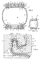
- FIG. 1 is a diagrammatic perspective view of the improved air spring of the invention;
- FIG. 2 is an enlarged fragmentary vertical cross-sectional view of the improved air spring of FIG. 1;
- FIG. 3 is a further enlarged fragmentary sectional view of the snap-fitted connection of the end cap and clamp ring of the upper end member of the air spring of FIGS. 1 and 2;
- FIG. 4 is an exploded fragmentary view with portions in section showing a modified end member for sealing the ends of the sleeve of the improved air spring of the invention in disassembled position;
- FIG. 5 is a fragmentary sectional view of the modified end member of FIG. 4 in assembled position; and
- FIG 6 is a greatly enlarged fragmentary sectional view showing the various pinch areas and expansion areas provided by the modified end member of FIGS. 4 and 5.
- Similar numerals refer to similar parts throught the drawings.
- Referring now to the drawings and more particularly to FIGS. 1 and 2, the improved air spring of the invention is indicated generally at 10. The center portion of
air spring 10 is formed by a cylindrically tubular-shaped sleeve 12 which is formed to an appropriate length from suitableelastomeric material 13 containing reinforcing fabric formed bybiased cords 14, shown particularly in FIG. 3, without a separate reinforcing bead being molded into either end of the sleeve as in prior art sleeve constructions. An end cap assembly or end member indicated generally at 15, is secured tosleeve 12 at opposite ends thereof.Cap assemblies 15 are adapted to be secured to portions of a vehicle or other spaced structures between which relative movement is to be dampened. The uses of the air spring of the instant invention are no different from those previously known, the invention herein residing in the structure and more particularly the sealing of the sleeve ends to form apressurized fluid chamber 18 therein byend cap 15. - Each
end cap assembly 15 preferably is similar and therefore only one is shown and described in detail.End cap assembly 15 comprises a generally disc-shaped end cap 16 interconnected with anannular clamp ring 20.Ring 20 comprises an outercylindrical side wall 22 which is normal and upstanding to an annular base 24 (FIG. 3). - In accordance with the main feature of the invention the inner end of
annular base 24 terminates in an upwardly extendingprojection 26 which is spaced radially inwardly fromsidewall 22 and which terminates in arounded top end 28. An annularconcave recess 29 is formed outwardly ofprojection 26 and is separated fromsidewall 22 by anannular shoulder 30 also formed as a part ofbase 24. The inside surface ofwall 22 is cylindrical and terminates in a snap-lip 31 having abeveled edge 32. The inner surface ofring 20 defined byprojection 26,concave recess 29,shoulder 30, and cylindricalinner surface 33 ofcylindrical wall 22 is collectively referred to as a mating surface and is indicated generally at 35. -
End cap 16 is formed with an inner mating surface indicated generally at 37, formed with a main inner concave recess indicated generally at 38 which axially aligns with and receives a portion ofprojection 26 ofclamp ring 20.Mating surface 37 further includes an annular relatively flat radially extending area 39 which terminates in an outwardly tapered inclinedannular surface 40 which converges towardsidewall 22 ofclamp ring 20.Surface 40 terminates in a snap-lip 42 having abeveled surface 43 which is clampingly engaged with thebeveled edge 32 of snap-lip 31. - One of the main features of the invention is the alignment of
mating surfaces side surfaces 48 ofprojection 26 and the generally parallel axially extending side surfaces 50 which formconcave recess 38. The radial distance betweenaligned surfaces 48 and 50, which are generally parallel to each other as shown in FIG. 3, is preferably approximately 50% of the uncompressed thickness ofelastomeric material 13 ofsleeve 12. Thus upon the axial engagement ofend cap 16 withclamp ring 20, the elastomeric material in the pinch areas indicated at 52 and 53, is placed in shear compression securing the sleeve tightly therebetween. - In further accordance with the invention, rounded the
top end 28 ofprojection 26, is spaced frombottom surface 55 of concave recess 38 a distance greater than the thickness ofmaterial 13 providing an expansion zone or area for movement of the compressed rubber in the pinch areas to expand or flow into the expansion area which is indicated at 56. - As shown in FIG. 3, reinforcing
cord 14 moves through a direction change of approximately 180° when moving frompinch area 45 throughexpansion area 56 and then throughpinch area 46. This change of direction places a downward tensile load on the cord as shown by arrow A in moving throughpinch area 45 and placing an upward tensile load on the cord as indicated by arrow B, when moving throughpinch area 46. The particular configuration ofmating surfaces sleeve 12 to maintain it in a secured clamped position betweenend cap 16 andclamp ring 20. - The bottom of
concave recess 29 ofclamp ring 20 is spaced a sufficient distance, a distance greater than the thickness ofmaterial 13, from flat radial surface 39 ofend cap 16 to provide asecond expansion area 58. This is followed by athird pinch area 59 formed betweenannular shoulder 30 and radial flat surface 39 providing additional holding and clamping action on the sleeve end. Anouter expansion area 60, having a generally triangular configuration, is formed between end captapered surface 40 and innercylindridal surface 33 ofclamp ring sidewall 22 to permit any remaining rubber caused bypinch area 59 which does not flow intoexpansion area 58 to have a void area in which to flow to permit the satisfactory snap joining ofend cap 16 withclamp ring 20. - The particular configuration of
mating surfaces sleeve 12 to form around various contours, and when combined with the pinch areas and expansion areas, has been found to provide an extremely strong clamping action between the end cap and sealing ring enabling the internal pressure withinchamber 18 to be increased to a pressure at least equal to that provided by end clamping members in which the sleeve has internally molded reinforcing clamping beads or bands. - Since the rubber or
elastomeric material 13 is generally incompressible after reaching a certain amount of compression,expansion areas cap 16 andring 20 at spacedpinch areas fabric cord 14 as it moves through the spaced pinch areas and intervening expansion area and into the final expansion areas is believed to provide the resistance to the disengagement of the clamped sleeve material from betweenend cap 16 andring 20.End cap 16 is formed with a plurality of threadedholes 54 for securing the end cap to a vehicle or the like withupper end cap 16 being provided with a threadedopening 62 for receiving the nipple of a pressure valve for connecting the air spring to a pressure source for pressurizingchamber 18. - With continued reference to FIGS. 1 - 3, it can be seen that
end cap 16 may be easily positioned at the end of thesleeve 12. To do so, thebead ring 20 is first slid over the outer periphery of elastomeric sleeve 12 a predefined distance. With the inner diameter of thering 20 being less than the outer diameter of thesleeve 12, the rubber ofsleeve 12 is drawn inwardly within the ring. Next, theend cap 16 is brought within the end opening ofsleeve 12 as it extends throughring 20, securing the elastomeric material of the sleeve between the outer peripheral contouredmating surface 37 ofend cap 16 and the generally similarly shapedinner mating surface 35 ofring 20. The clamping forces developed between mating surfaces 35 and 37 as discussed above preventsleeve 12 from slipping or moving whileend cap 16 is engaged withring 20. - It will be readily appreciated that, in operation,
end cap assemblies 15 are secured to relatively movable members such as on a vehicle. It will also be understood thatfluid pressure chamber 18 defined by thesleeve 12, is pressurized to provide the spring action. With movement of the end caps relatively restricted, the pressure force withinchamber 18 exerts radial, rather than axial force on the mating seals defined by the spaced concentric projections and recesses of the mating surfaces maintaining compressed sleeve material therebetween. This force tends to increase the effectiveness of sealing or clamping action as the internal pressure increases. - A modified form of the improved air spring, and in particular, the end cap assembly therefor, is indicated generally at 64 and is shown in FIGS. 4, 5 and 6. The modified end cap assembly includes an end cap and clamping ring indicated generally at 65 and 66 respectively.
End cap 65 is a solid disc-shaped member having anouter surface 67 formed with ahelical projection 68 which forms a intervening helical-shapedrecess 69.Helical projection 68 is formed with roundedouter surfaces 73 to prevent cutting intoelastomeric material 13 as described below. As shown in FIG. 5 a plurality of threaded mountingholes 71 and a threadedpressure supply opening 72 are provided inend cap 65 for mounting the air spring to a supporting structure and to provide for the flow of pressurized fluid intofluid chamber 18 of the air spring in a usual manner well known in the art.Clamp ring 66 is annular-shaped having an inner mating surface indicated generally at 75, formed by anhelical projection 76 forming an intervening helical-shapedconcave recess 77. - Referring to FIGS. 4 and 5, the outer end of
sleeve 12 is inserted through the interior ofclamp ring 66 followed by the engagement ofend cap 65 therein by a rotational motion similar to the threaded engagement of an externally threaded member into an internally threaded opening. In accordance with the principles of the invention,helical projection 68 ofend cap 65 extends into helicalconcave recess 77 ofclamp ring 66 as shown in FIG. 6 to provide a series of pinch areas or zones, each of which is indicated bynumeral 79. These pinch areas are followed by interveningexpansion areas 80 whereby at least a pair of compressive shear areas are applied on the elastomeric material ofsleeve 12 separated by an expansion areas whereby the rubber squeezed from the shear compressive areas flow into the intervening expansion area. Furthermore,cord 14 moving through a change in direction of approximately 180° when moving from one pinch area into a second pinch area with the tension exerted on the cord also reversing from an inward to an outward direction with respect to the longitudinal dimension or axis ofsleeve 12 in a similar manner as described above with respect to endcap 16 andclamp ring 20. - Again, the combination of two pinch areas between the end cap and clamp ring which forms the pair of pinch areas to place the intervening sleeve material in shear compression, together with the intervening expansion zone, has been found to provide a secure clamping engagement with the sleeve end to enable the air spring to withstand sufficient internal pressure for its desired application.
- Accordingly, the improved beadless air spring is simplified, provides an effective, safe, inexpensive, and efficient device which achieves all the enumerated objectives, provides for eliminating difficulties encountered with prior devices, and solves problems and obtains new result in the art.
- In the foregoing description, certain terms have been used for brevity, clearness and understanding; but no unnecessary limitations are to be implied therefrom beyond the requirements of the prior art, because such terms are used for descriptive purposes and are intended to be broadly construed.
- Moreover, the description and illustration of the invention is by way of example, and the scope of the invention is not limited to the exact details shown or described.
- Having now described the features, discoveries and principles of the invention, the manner in which the improved beadless air spring is constructed and used, the characteristics of the construction and the advantageous, new and useful results obtained; and new and useful structures, devices, elements, arrangements, parts and combinations are set forth in the appended claims.
Claims (12)
Applications Claiming Priority (2)
| Application Number | Priority Date | Filing Date | Title |
|---|---|---|---|
| US07/062,987 US4784376A (en) | 1987-06-17 | 1987-06-17 | End cap assembly for air spring |
| US62987 | 1998-04-20 |
Publications (3)
| Publication Number | Publication Date |
|---|---|
| EP0295393A2 true EP0295393A2 (en) | 1988-12-21 |
| EP0295393A3 EP0295393A3 (en) | 1989-04-12 |
| EP0295393B1 EP0295393B1 (en) | 1991-05-29 |
Family
ID=22046145
Family Applications (1)
| Application Number | Title | Priority Date | Filing Date |
|---|---|---|---|
| EP88106452A Expired - Lifetime EP0295393B1 (en) | 1987-06-17 | 1988-04-22 | End cap assembly for air spring |
Country Status (6)
| Country | Link |
|---|---|
| US (1) | US4784376A (en) |
| EP (1) | EP0295393B1 (en) |
| JP (1) | JP2825495B2 (en) |
| AU (1) | AU608596B2 (en) |
| BR (1) | BR8802960A (en) |
| DE (1) | DE3863007D1 (en) |
Cited By (3)
| Publication number | Priority date | Publication date | Assignee | Title |
|---|---|---|---|---|
| DE10050777A1 (en) * | 2000-10-13 | 2002-05-02 | Continental Ag | Air spring for motor vehicle, has concave-shaped clamp seats to hold ends of flexible spring by convex clamp rings |
| CN106989132A (en) * | 2016-01-20 | 2017-07-28 | 威巴克商用车辆气动弹簧有限责任公司 | Air spring |
| EP4008572A1 (en) * | 2020-12-02 | 2022-06-08 | ContiTech AG | Air spring |
Families Citing this family (25)
| Publication number | Priority date | Publication date | Assignee | Title |
|---|---|---|---|---|
| DE3824542A1 (en) * | 1988-07-20 | 1990-01-25 | Sauer Achsenfab | SUBMERSIBLE PISTON ARRANGEMENT |
| US5060916A (en) * | 1988-07-20 | 1991-10-29 | Otto Sauer Achsenfabrik Keilberg | Plunger piston system |
| US4899995A (en) * | 1988-12-29 | 1990-02-13 | Bridgestone/Firestone, Inc. | Clamp ring assembly for air spring |
| US4852861A (en) * | 1988-12-29 | 1989-08-01 | The Firestone Tire & Rubber Company | End cap assembly for air spring |
| US4946144A (en) * | 1989-03-30 | 1990-08-07 | Bridgestone/Firestone, Inc. | External clamping band for air spring |
| JPH06507227A (en) * | 1991-04-29 | 1994-08-11 | パトン,エイチ.ネイル | Composite elastomer springs and mounting devices |
| DE4133878C2 (en) * | 1991-10-12 | 1995-04-13 | Continental Ag | Air spring with a hose bellows made of elastomeric material |
| DE4142561C2 (en) * | 1991-12-21 | 1995-04-27 | Continental Ag | Air spring with a beadless air spring bellows made of elastomeric material |
| US5374037A (en) * | 1993-09-20 | 1994-12-20 | Bridgestone/Firestone, Inc. | Clamp ring assembly for air spring |
| US5460354A (en) * | 1994-06-24 | 1995-10-24 | Bridgestone/Firestone, Inc. | Clamp assembly for air spring |
| DE10105769A1 (en) * | 2000-02-28 | 2001-08-30 | Phoenix Ag | Air spring has shock absorber which passes through top of piston and bellows fastened to top of piston by ring clip over which locking ring consisting of collar retained between inner and outer rings fits |
| US6264178B1 (en) | 2000-06-13 | 2001-07-24 | The Goodyear Tire & Rubber Company | Molded air sleeves |
| US6474630B1 (en) | 2001-04-24 | 2002-11-05 | Bfs Diversified Products, Llc | Air spring swage assembly |
| DE10163818B4 (en) * | 2001-12-22 | 2020-08-20 | Contitech Luftfedersysteme Gmbh | Hose roll bellows spring |
| US6619635B1 (en) | 2002-04-08 | 2003-09-16 | Bfs Diversified Products, Llc | Air spring clamping assembly |
| US6719279B1 (en) * | 2002-08-21 | 2004-04-13 | Bfs Diversified Products, Llc | Air spring sleeve |
| DE102004031875A1 (en) * | 2004-04-22 | 2005-11-17 | Zf Friedrichshafen Ag | Cover for an air spring |
| US7325794B2 (en) | 2005-06-06 | 2008-02-05 | Bfs Diversified Products, Llc | Air spring assembly and method |
| US7404547B2 (en) * | 2005-07-27 | 2008-07-29 | Bfs Diversified Products, Llc | Multi-component end member assembly and air spring assembly including the same |
| NO328199B1 (en) * | 2008-02-13 | 2010-01-04 | Fmc Kongsberg Subsea As | Device for repelling a riser |
| EP2775162B1 (en) | 2013-03-08 | 2019-10-30 | ContiTech USA, Inc. | Composite bead plate and an air spring using the same |
| WO2014190123A1 (en) | 2013-05-22 | 2014-11-27 | Firestone Industrial Products Company, Llc | End member and gas spring assembly including same |
| DE102015108519B3 (en) * | 2015-05-29 | 2016-07-28 | Saf-Holland Gmbh | support unit |
| EP3374210A1 (en) * | 2015-11-09 | 2018-09-19 | Firestone Building Products Co., LLC | Flexible spring members as well as gas spring assemblies and methods of manufacture |
| DE102017213700A1 (en) * | 2017-08-07 | 2019-02-07 | Contitech Luftfedersysteme Gmbh | sealing arrangement |
Citations (12)
| Publication number | Priority date | Publication date | Assignee | Title |
|---|---|---|---|---|
| US1929857A (en) * | 1931-11-23 | 1933-10-10 | Joseph B Strauss | Auto pneumatic spring for vehicles |
| US2874458A (en) * | 1955-10-10 | 1959-02-24 | Firestone Tire & Rubber Co | Method of making an air spring |
| US2977134A (en) * | 1957-09-18 | 1961-03-28 | Fried Krupp Mortoren Und Kraft | Device for controlling the air in air springs, especially for motor vehicles |
| US3038717A (en) * | 1957-02-04 | 1962-06-12 | Firestone Tire & Rubber Co | Air spring |
| GB907555A (en) * | 1958-03-06 | 1962-10-10 | Dunlop Rubber Co | Fluid spring assembly |
| US3788628A (en) * | 1972-11-10 | 1974-01-29 | Wright Barry Corp | Pneumatic isolator |
| US3790147A (en) * | 1972-11-17 | 1974-02-05 | Gen Motors Corp | Height control valve for air spring with end piston-boot operated |
| FR2356028A1 (en) * | 1976-06-24 | 1978-01-20 | Ferodo Sa | Sleeve-type pneumatic actuator - has membrane fitting over ring distance pieces or coil spring and bulging inwards when sleeve is evacuated |
| GB2044395A (en) * | 1979-03-08 | 1980-10-15 | Goodyear Tire & Rubber | Attaching Diaphragm of Rolling Lobe Airspring |
| US4325541A (en) * | 1977-06-30 | 1982-04-20 | Autoipari Kutato Intezet | Spring leg which has a load proportionally limited damping, consisting of an air suspension and a telescopic shock absorber for motor vehicle |
| EP0123171A2 (en) * | 1983-04-21 | 1984-10-31 | The Firestone Tire & Rubber Company | Clamp for non-beaded pneumatic assemblies |
| US4506910A (en) * | 1982-09-21 | 1985-03-26 | Granning Suspensions, Inc. | Automotive vehicle suspension |
Family Cites Families (5)
| Publication number | Priority date | Publication date | Assignee | Title |
|---|---|---|---|---|
| GB779809A (en) * | 1954-12-14 | 1957-07-24 | Continental Gummi Werke Ag | Improvements in or relating to pneumatic shock absorbers |
| FR1168845A (en) * | 1956-03-27 | 1958-12-17 | Daimler Benz Ag | Elastic bellows for elastic air suspensions |
| JPS4415705Y1 (en) * | 1964-03-30 | 1969-07-07 | ||
| US4378935A (en) * | 1979-03-08 | 1983-04-05 | The Goodyear Tire & Rubber Company | Rolling lobe airspring |
| US4787606A (en) * | 1987-06-17 | 1988-11-29 | The Firestone Tire & Rubber Company | Beadless air spring |
-
1987
- 1987-06-17 US US07/062,987 patent/US4784376A/en not_active Expired - Lifetime
-
1988
- 1988-04-21 AU AU15031/88A patent/AU608596B2/en not_active Ceased
- 1988-04-22 DE DE8888106452T patent/DE3863007D1/en not_active Expired - Lifetime
- 1988-04-22 EP EP88106452A patent/EP0295393B1/en not_active Expired - Lifetime
- 1988-06-10 JP JP63141869A patent/JP2825495B2/en not_active Expired - Lifetime
- 1988-06-16 BR BR8802960A patent/BR8802960A/en unknown
Patent Citations (12)
| Publication number | Priority date | Publication date | Assignee | Title |
|---|---|---|---|---|
| US1929857A (en) * | 1931-11-23 | 1933-10-10 | Joseph B Strauss | Auto pneumatic spring for vehicles |
| US2874458A (en) * | 1955-10-10 | 1959-02-24 | Firestone Tire & Rubber Co | Method of making an air spring |
| US3038717A (en) * | 1957-02-04 | 1962-06-12 | Firestone Tire & Rubber Co | Air spring |
| US2977134A (en) * | 1957-09-18 | 1961-03-28 | Fried Krupp Mortoren Und Kraft | Device for controlling the air in air springs, especially for motor vehicles |
| GB907555A (en) * | 1958-03-06 | 1962-10-10 | Dunlop Rubber Co | Fluid spring assembly |
| US3788628A (en) * | 1972-11-10 | 1974-01-29 | Wright Barry Corp | Pneumatic isolator |
| US3790147A (en) * | 1972-11-17 | 1974-02-05 | Gen Motors Corp | Height control valve for air spring with end piston-boot operated |
| FR2356028A1 (en) * | 1976-06-24 | 1978-01-20 | Ferodo Sa | Sleeve-type pneumatic actuator - has membrane fitting over ring distance pieces or coil spring and bulging inwards when sleeve is evacuated |
| US4325541A (en) * | 1977-06-30 | 1982-04-20 | Autoipari Kutato Intezet | Spring leg which has a load proportionally limited damping, consisting of an air suspension and a telescopic shock absorber for motor vehicle |
| GB2044395A (en) * | 1979-03-08 | 1980-10-15 | Goodyear Tire & Rubber | Attaching Diaphragm of Rolling Lobe Airspring |
| US4506910A (en) * | 1982-09-21 | 1985-03-26 | Granning Suspensions, Inc. | Automotive vehicle suspension |
| EP0123171A2 (en) * | 1983-04-21 | 1984-10-31 | The Firestone Tire & Rubber Company | Clamp for non-beaded pneumatic assemblies |
Cited By (6)
| Publication number | Priority date | Publication date | Assignee | Title |
|---|---|---|---|---|
| DE10050777A1 (en) * | 2000-10-13 | 2002-05-02 | Continental Ag | Air spring for motor vehicle, has concave-shaped clamp seats to hold ends of flexible spring by convex clamp rings |
| US6749184B2 (en) | 2000-10-13 | 2004-06-15 | Continental Aktiengesellschaft | Air spring and method for making the same |
| DE10050777B4 (en) * | 2000-10-13 | 2004-09-30 | Continental Aktiengesellschaft | Air spring and method for manufacturing an air spring |
| CN106989132A (en) * | 2016-01-20 | 2017-07-28 | 威巴克商用车辆气动弹簧有限责任公司 | Air spring |
| EP4008572A1 (en) * | 2020-12-02 | 2022-06-08 | ContiTech AG | Air spring |
| WO2022117293A1 (en) * | 2020-12-02 | 2022-06-09 | Contitech Ag | Air spring |
Also Published As
| Publication number | Publication date |
|---|---|
| JP2825495B2 (en) | 1998-11-18 |
| US4784376A (en) | 1988-11-15 |
| AU608596B2 (en) | 1991-04-11 |
| DE3863007D1 (en) | 1991-07-04 |
| EP0295393B1 (en) | 1991-05-29 |
| BR8802960A (en) | 1989-01-10 |
| JPS63318335A (en) | 1988-12-27 |
| EP0295393A3 (en) | 1989-04-12 |
| AU1503188A (en) | 1988-12-22 |
Similar Documents
| Publication | Publication Date | Title |
|---|---|---|
| US4784376A (en) | End cap assembly for air spring | |
| US4787606A (en) | Beadless air spring | |
| US4852861A (en) | End cap assembly for air spring | |
| US5374037A (en) | Clamp ring assembly for air spring | |
| US4787607A (en) | Air spring having internal sealing band and method of installing same | |
| AU625279B2 (en) | Clamp ring assembly for air spring | |
| US4946144A (en) | External clamping band for air spring | |
| US5941509A (en) | Clamp assembly for air actuator | |
| US6036180A (en) | Tear-drop shaped clamp assembly and tapered end cap for an air spring | |
| US4793598A (en) | Air spring having internal sealing band and method of installing same | |
| EP0264573A2 (en) | Air spring having internal sealing band and method of installing same | |
| CA1293005C (en) | End cap assembly for air spring | |
| MXPA98003033A (en) | Clamp assembly for actuator of a | |
| CA2235171A1 (en) | Clamp assembly for air actuator |
Legal Events
| Date | Code | Title | Description |
|---|---|---|---|
| PUAI | Public reference made under article 153(3) epc to a published international application that has entered the european phase |
Free format text: ORIGINAL CODE: 0009012 |
|
| AK | Designated contracting states |
Kind code of ref document: A2 Designated state(s): DE FR GB SE |
|
| PUAL | Search report despatched |
Free format text: ORIGINAL CODE: 0009013 |
|
| AK | Designated contracting states |
Kind code of ref document: A3 Designated state(s): DE FR GB SE |
|
| 17P | Request for examination filed |
Effective date: 19890331 |
|
| 17Q | First examination report despatched |
Effective date: 19900202 |
|
| GRAA | (expected) grant |
Free format text: ORIGINAL CODE: 0009210 |
|
| AK | Designated contracting states |
Kind code of ref document: B1 Designated state(s): DE FR GB SE |
|
| REF | Corresponds to: |
Ref document number: 3863007 Country of ref document: DE Date of ref document: 19910704 |
|
| ET | Fr: translation filed | ||
| PLBE | No opposition filed within time limit |
Free format text: ORIGINAL CODE: 0009261 |
|
| STAA | Information on the status of an ep patent application or granted ep patent |
Free format text: STATUS: NO OPPOSITION FILED WITHIN TIME LIMIT |
|
| 26N | No opposition filed | ||
| EAL | Se: european patent in force in sweden |
Ref document number: 88106452.1 |
|
| PGFP | Annual fee paid to national office [announced via postgrant information from national office to epo] |
Ref country code: SE Payment date: 20010405 Year of fee payment: 14 |
|
| REG | Reference to a national code |
Ref country code: GB Ref legal event code: IF02 |
|
| PG25 | Lapsed in a contracting state [announced via postgrant information from national office to epo] |
Ref country code: SE Free format text: LAPSE BECAUSE OF NON-PAYMENT OF DUE FEES Effective date: 20020423 |
|
| EUG | Se: european patent has lapsed |
Ref document number: 88106452.1 |
|
| REG | Reference to a national code |
Ref country code: GB Ref legal event code: 732E |
|
| PGFP | Annual fee paid to national office [announced via postgrant information from national office to epo] |
Ref country code: FR Payment date: 20040402 Year of fee payment: 17 |
|
| REG | Reference to a national code |
Ref country code: FR Ref legal event code: CD Ref country code: FR Ref legal event code: TP |
|
| REG | Reference to a national code |
Ref country code: FR Ref legal event code: TP |
|
| PG25 | Lapsed in a contracting state [announced via postgrant information from national office to epo] |
Ref country code: FR Free format text: LAPSE BECAUSE OF NON-PAYMENT OF DUE FEES Effective date: 20051230 |
|
| REG | Reference to a national code |
Ref country code: FR Ref legal event code: ST Effective date: 20051230 |
|
| PGFP | Annual fee paid to national office [announced via postgrant information from national office to epo] |
Ref country code: GB Payment date: 20070313 Year of fee payment: 20 |
|
| PGFP | Annual fee paid to national office [announced via postgrant information from national office to epo] |
Ref country code: DE Payment date: 20070430 Year of fee payment: 20 |
|
| REG | Reference to a national code |
Ref country code: GB Ref legal event code: PE20 Expiry date: 20080421 |
|
| PG25 | Lapsed in a contracting state [announced via postgrant information from national office to epo] |
Ref country code: GB Free format text: LAPSE BECAUSE OF EXPIRATION OF PROTECTION Effective date: 20080421 |