EP0295355B1 - An insertion controller for alternate weaving with different wefts on a fluid jet loom - Google Patents
An insertion controller for alternate weaving with different wefts on a fluid jet loom Download PDFInfo
- Publication number
- EP0295355B1 EP0295355B1 EP87810693A EP87810693A EP0295355B1 EP 0295355 B1 EP0295355 B1 EP 0295355B1 EP 87810693 A EP87810693 A EP 87810693A EP 87810693 A EP87810693 A EP 87810693A EP 0295355 B1 EP0295355 B1 EP 0295355B1
- Authority
- EP
- European Patent Office
- Prior art keywords
- weft
- signal
- selector
- circuit
- manual
- Prior art date
- Legal status (The legal status is an assumption and is not a legal conclusion. Google has not performed a legal analysis and makes no representation as to the accuracy of the status listed.)
- Expired - Lifetime
Links
- 238000003780 insertion Methods 0.000 title claims description 47
- 230000037431 insertion Effects 0.000 title claims description 47
- 238000009941 weaving Methods 0.000 title claims description 11
- 239000012530 fluid Substances 0.000 title description 11
- 230000005540 biological transmission Effects 0.000 claims description 4
- 238000010276 construction Methods 0.000 description 17
- 238000010586 diagram Methods 0.000 description 6
- 230000000994 depressogenic effect Effects 0.000 description 5
- 230000006872 improvement Effects 0.000 description 5
- 230000007547 defect Effects 0.000 description 4
- 238000005259 measurement Methods 0.000 description 4
- 230000008439 repair process Effects 0.000 description 4
- 238000005086 pumping Methods 0.000 description 2
- XLYOFNOQVPJJNP-UHFFFAOYSA-N water Substances O XLYOFNOQVPJJNP-UHFFFAOYSA-N 0.000 description 2
- 230000008859 change Effects 0.000 description 1
- 238000001514 detection method Methods 0.000 description 1
- 238000000034 method Methods 0.000 description 1
- 230000008569 process Effects 0.000 description 1
- 230000004044 response Effects 0.000 description 1
Images



Classifications
-
- D—TEXTILES; PAPER
- D03—WEAVING
- D03D—WOVEN FABRICS; METHODS OF WEAVING; LOOMS
- D03D47/00—Looms in which bulk supply of weft does not pass through shed, e.g. shuttleless looms, gripper shuttle looms, dummy shuttle looms
- D03D47/28—Looms in which bulk supply of weft does not pass through shed, e.g. shuttleless looms, gripper shuttle looms, dummy shuttle looms wherein the weft itself is projected into the shed
-
- D—TEXTILES; PAPER
- D03—WEAVING
- D03D—WOVEN FABRICS; METHODS OF WEAVING; LOOMS
- D03D47/00—Looms in which bulk supply of weft does not pass through shed, e.g. shuttleless looms, gripper shuttle looms, dummy shuttle looms
- D03D47/28—Looms in which bulk supply of weft does not pass through shed, e.g. shuttleless looms, gripper shuttle looms, dummy shuttle looms wherein the weft itself is projected into the shed
- D03D47/30—Looms in which bulk supply of weft does not pass through shed, e.g. shuttleless looms, gripper shuttle looms, dummy shuttle looms wherein the weft itself is projected into the shed by gas jet
- D03D47/3026—Air supply systems
- D03D47/3033—Controlling the air supply
- D03D47/3046—Weft yarn selection
Definitions
- the present invention relates to an insertion controller according to the preamble clause of claim 1, and more particularly relates to an improvement in a weft insertion control system for alternate weaving with different wefts on a fluid jet loom on which different wefts are inserted into sheds following a regular sequential weft selection pattern via different main nozzles by sequential drive of a weft inserting unit in accordance with commands from an automatic weft selector.
- weft insertion is carried out following the regular sequential weft selection pattern fixed by the commands given by the automatic weft selector and no special trouble starts in this mode of weaving as long as the loom performs its normal running.
- a signal reservation circuit is interposed between an automatic weft selector and a driver circuit, a control box of the loom and a manual weft selector are connected to the signal reservation circuit and to the driver circuit, the driver circuit is made to operate following a regular sequential weft selection pattern fixed by commands from the automatic weft selector during normal running of the loom, and, at stoppage of the loom, the driver circuit is made to operate following a free selective weft selection pattern fixed by commands from the manual weft selector with priority to the regular sequential weft selection pattern.
- Such adjustment includes adjustment in, for example, fluid pressure, timing of fluid ejection, position of the nozzles and other process factors influencing the state of weft insertion.
- a stroboscope may be used for measurement of the state of weft insertion.
- a number of wefts different in type are inserted following a regular sequential weft selection pattern and, as a consequence, it is quite impossible to measure the state of weft insertion of a particular weft repeatedly in succession.
- Japanese Utility Model Opening Sho.62-114080 proposes a system to perform such a measurement even in the case of alternate weaving.
- a stroboscope is activated in synchronism with insertion of a particular weft only in order to selectively measure the state of weft insertion of that particular weft.
- alternate weaving is carried out following a given regular sequential weft selection pattern, some wefts may appear in sheds at short intervals and some wefts may appear in sheds at long intervals.
- the wefts of long intervals require a long time for measurement of their state of weft insertion.
- the system of the earlier proposal is unsuited for measurement of the state of weft insertion following some types of regular sequential weft selection patterns.
- shift in weft selection mode that is from the regular sequential to the free selective weft selection pattern, is caused depending on the state (H/L) of the output signal from the control box of the loom. So, the free selective weft selection can be introduced only at stoppage of the loom when the output signal is at the H-level.
- EP-A-0 114 339 shows a weft reservoir controller comprising a central processing unit which controls weft reservation following a stored program, in connection with a weft insertion command generator.
- This central Processing unit is provided with a manual release switch which is used for operating the weft reservoirs quite independently of the program followed by the central processing unit. However the release switch does not change operation of the weft insertion command generator.
- An insertion controller is characterized in that a signal reservation circuit is interposed between said automatic weft selector and said driver circuit in order to control transmission of said commands from said automatic weft selector, in that said manually operated means comprise a manual weft selector provided with push buttons in connection with said signal reservation circuit, and in that, on manual selection of one said push button, said manual weft selector on one hand passes a drive signal to an input terminal of said driver circuit which corresponds to said one push button and, on the other hand, passes a signal to said signal reservation circuit in order to inhibit transmission of said commands from said automatic weft selector.
- Fig. 1 shows the general construction of a weft inserting system on a fluid jet loom incorporating an improved insertion controller which enables free weft insertion at stoppage of the loom.
- the system includes a driver circuit 20, a weft inserting unit 30 electrically connected to the driver circuit 20 and an automatic weft selector 40.
- a signal reservation circuit 100 is interposed between the automatic weft selector 40 and the driver circuit 20.
- a control box 10 and a manual weft selector PB are electrically connected to the signal reservation circuit 100 and to the driver circuit 20.
- the driver circuit 20 is also electrically connected to weft reservoirs RS1 to RSn.
- wefts W1 to Wn are sequentially delivered from the weft reservoirs RS1 to RSn in order to be inserted into corresponding sheds via main nozzles N1 to Nn which are hydraulically connected to the weft inserting unit 30 in a known manner.
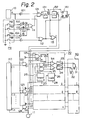
- Fig.2 shows one embodiment of the detailed construction of the weft inserting system shown in Fig.1.
- the control box 10 issues a two-value signal A which assumes a H-level during normal running and a L-level at stoppage of the loom.
- This control box 10 is connected on one hand to one input terminal of an AND-gate 121 via an inverter 101 and on the other hand to one input terminal of an OR-gate 112.
- the manual weft selector PB includes n sets of push buttons PB1 to PBn and a reset push button PBR, n corresponding to the number of the main nozzles N1 to Nn, i.e. the number of the different wefts W1 to Wn.
- a signal of L-level is issued on its corresponding line.
- the push buttons PB1 to PBn are connected one hand to the input terminal of an OR-gate 111 via respective inverters 102 to 104 and, on the other hand, to the input side of the driver circuit 20 in series therewith.
- the reset push button PBR is connected to the other terminal of the OR-gate 112.
- the AND-gate 121 is connected to a one-shot circuit 131 which issues an output signal D.
- the one-shot circuit 131 is connected to the S-terminal of a flip-flop circuit 141 and to a one-shot circuit 132 which issues an output signal E.
- the one-shot circuit 131 is further connected to one input terminal of an OR-gate 113 which issues an output signal J.
- the one-shot circuit 132 is connected to the driver circuit 20 as later described in more detail.
- the OR-gate 112 is connected on one hand to the R-terminal of the flip-flap circuit 141 and, on the other hand, to the other input terminal of the OR-gate 113.
- the OR-gate 113 is also connected to the driver circuit 20.
- the flip-flop circuit 141 is connected to the driver circuit 20 and issues an output signal F.
- the automatic weft selector 40 which issues output signals (colour signals) C1 to Cn, includes n sets of weft selections.
- the automatic weft selector 40 is connected, in parallel, to the driver circuit 20 via AND-gates 122 to 124 which issue output signals G1 to Gn.
- the above-described flip-flop circuit 141 is also connected to the AND-gates 122 to 124.
- the driver circuit 20 includes n sets of similar drive units for the wefts W1 to Wn, only the drive unit I being illustrated in Fig.2.
- the drive unit I includes an AND-gate 125 whose input terminal is connected to the one-shot circuit 132 and the push button PB1.
- the AND-gate 125 is connected to the S-terminal of a flip-flop circuit 142 which issues an output signal K.
- the R-terminal of this flip-flop circuit 142 is connected to the OR-gate 113.
- the AND-gate 122 is connected, in parallel, to one input terminals of AND-gates 21 and 22 whose other input terminals are connected, respectively, to setters 27 and 28 via comparators 25 and 26.
- An encoder 11 on the main shaft of the loom is connected to the comparator 25 and 26 for detection of angle of shaft rotation. The angle of shaft rotation is compared with the weft inserting period set by the setters 27 and 28 for issue of H-level signals from the comparators 25 and 26 during weft insertion.
- the Q-terminal of the flip-flop circuit 142 is connected to one input terminals of OR-gate 14 and 115.
- the other input terminals of the OR-gates 114 and 115 are connected to the AND-gates 21 and 22.
- the weft inserting unit 30 includes n sets of similar sub-units for the wefts W1 to Wn, only the sub-unit I being illustrated in Fig.2.
- the sub-unit I includes a gripper 31 connected to the OR-gate 114 via an amplifier 23 and an electromagnetic valve 32 connected to the OR-gate 115 via an amplifier 24.
- the weft W1 is to be inserted following a command given by the automatic weft selector 40 during normal running of the loom.
- the colour signal C1 assumes a H-level
- the output signal F from the flip-flop circuit 141 assumes a H-level
- the output signal G1 from the AND-gate 122 assumes a H-level. Since a weft is to be inserted, the output signals from the comparators 25 and 26 both assume H-levels.
- the OR-gate 114 and 115 both issue output signals of H-level to activate the sub-unit I of the weft inserting unit 30.
- the colour signals C2 to Cn all assume L-levels and the output signals G2 to Gn all assume L-levels so that the sub-units II to n should not operate.
- the output signal A from the control box 10 assumes a L-level.
- the output signal F assumes a H-level whereas the output signal J assumes a L-level.
- the output signal G2 from the AND-gate 123 assumes a H-level.
- the output signal B1 from the manual weft selector PB assumes a H-level and the output signal F from the flip-flop 141 assumes a L-level.
- the output signal G2 from the AND-gate 123 is made to assume a L-level and only the output signal K from the flip-flop circuit 142 of the drive unit I assumes a H-level.
- only the sub-unit I of the weft inserting unit 30 is put under an operable condition and the weft W1 is passed to the main nozzle N1 by means of a proper manual operation such as depression of a foot pedal.
- the regular sequential weft selection pattern fixed by the commands from the automatic weft selector 40 is provisionally ignored and reserved at the signal reservation circuit 100.
- the reset push button PBR is depressed for example at a moment t4 and the output signal J assumes a H-level.
- the output signal F from the flip-flop circuit 141 assumes a H-level
- the output signal G2 from the AND-gate 123 assumes a H-level
- the output signal K from the flip-flop circuit 142 assumes a L-level.
- the sub-unit I is deactivated and the sub-unit II is activated in the weft inserting unit 30.
- the regular sequential weft selection pattern fixed by the commands from the automatic weft selector 40 is resumed for insertion of the weft W2.
- Fig.4 shows another embodiment of the detailed construction of the weft inserting system shown in Fig.1. Although basically same as the foregoing embodiment, this construction is different in the following points.
- Fig.5 The operation of this weft inserting system is shown in Fig.5 in which time is again taken on the abscissa.
- the loom runs normally during a period from t1 to t2 and is at stoppage during a period from t2 to t5.
- the push button PB1 is depressed during a period from t3 to t4.
- a lever L2 is pivoted to a shaft in connection with a foot pedal FP.
- the lever L2 is placed outside operative zone of a lever L1.
- the foot pedal FP When the foot pedal FP is depressed, the lever L2 lowers and a roller carried thereby pushes down one end of the lever Ll for suction by pumping.
- depression on the foot pedal FP is removed, the lever L2 resumes its initial position via spring force for ejection by pumping (ejection of water).
- controllers are similarly usable for a weft inserting system on an air jet loom too.
- Fig.8 shows the general construction of a weft inserting system on a fluid jet loom incorporating the insertion controller in accordance with the present invention.
- a signal reservation circuit 300 is interposed between an automatic weft selector 40 and a driver circuit 20' and a manual weft selector PB' is connected to the signal reservation circuit 300 and to the driver circuit 20'.
- the driver circuit 20' Is electrically connected to a weft inserting unit 30 and weft reservoirs RS1 to RSn.
- wefts W1 to Wn are sequentially delivered from the weft reservoirs for insertion via main nozzles N1 to Nn which are hydraulically connected to the weft inserting unit 30 in a known manner.
- Figs.9 and 10 show one embodiment of the detailed construction of the weft inserting system shown in Fig.8. In the following description, it is assumed that four types of different wefts are inserted in alternate sequence.
- relay contacts R1 to R4 in the driver circuit 20′ are controlled by a relay sequence circuit of the manual weft selector PB′ shown in Fig.10. Relays R1 to R4 in Fig.9 are activated by switches S1 to S4 in the manual weft selector PB′.
- the reset switch SR is manually closed so that the switch S1 should be made open.
- the connection to the constant voltage source +V is canceled and the relay contact R1 in the driver circuit 20′ resumes the condition shown in Fig.9, i.e. the condition during the normal running of the loom.
- relays are used for constructing the circuits.
- FIG.11 Another embodiment of the detailed construction of the weft inserting system is shown in Fig.11, in which logic elements are used for construction circuits.
- the signal reservation circuit 300 includes four sets of AND-gates and the driver circuit 20′ includes four sets of OR-gates.
- the manual weft selector PB′ includes five sets of switches S1 to SR and a NOR-gate connected, in parallel to these switches.
- the colour signals C1 to C4 are issued by the automatic weft selector 40 following a regular sequential weft selection pattern and each of them at a H-level is passed to the signal reservation circuit 300. Since the switches S1 to SR in the manual weft selector PB′ are all left open at this moment, a signal at a H-level is issued by the NOR-gate. As a consequence, signals at H-levels are passed to both input ternals of each AND-gate in the signal reservation circuit 300. On receipt of corresponding signals from the signal reservation circuit 300, the driver circuit 20′ issues the signals B1 to B4 in alternate sequence.
- adjustment of weft insertion can be performed at any time required regardless the running condition of the loom.
Landscapes
- Engineering & Computer Science (AREA)
- Textile Engineering (AREA)
- Looms (AREA)
Description
- The present invention relates to an insertion controller according to the preamble clause of
claim 1, and more particularly relates to an improvement in a weft insertion control system for alternate weaving with different wefts on a fluid jet loom on which different wefts are inserted into sheds following a regular sequential weft selection pattern via different main nozzles by sequential drive of a weft inserting unit in accordance with commands from an automatic weft selector. - In the case of the above-described type of fluid jet loom, weft insertion is carried out following the regular sequential weft selection pattern fixed by the commands given by the automatic weft selector and no special trouble starts in this mode of weaving as long as the loom performs its normal running.
- At stoppage of the loom, however, it is sometimes required to perform weft insertion in a sequence independent of the regular sequential weft insertion pattern fixed by the commands from the automatic selector for the purpose of, for example, repair of weft defects on any main nozzles. With the conventional weft selection system, however, such a free weft insertion is quite infeasible because the sequence of weft insertion is exclusively fixed by the commands from the automatic weft selector. Thus, repair of weft defects cannot be duly performed in the case of fluid jet looms equipped with such a conventional weft selection system.
- It is the object of a first improvement to enable free weft insertion, at stoppage of loom, in a sequence independent of a regular sequential weft insertion pattern fixed by commands from an automatic weft selector without any ill influence upon such a fixed pattern.
- In accordance with the above-mentioned first improvement a signal reservation circuit is interposed between an automatic weft selector and a driver circuit, a control box of the loom and a manual weft selector are connected to the signal reservation circuit and to the driver circuit, the driver circuit is made to operate following a regular sequential weft selection pattern fixed by commands from the automatic weft selector during normal running of the loom, and, at stoppage of the loom, the driver circuit is made to operate following a free selective weft selection pattern fixed by commands from the manual weft selector with priority to the regular sequential weft selection pattern.
- In practical alternate weaving with different weft, it is sometimes required to intercept the regular sequential weft selection pattern even during normal running of the loom for adjustment of weft insertion, in addition to the above-described sequence interception at stoppage of the loom. Such adjustment includes adjustment in, for example, fluid pressure, timing of fluid ejection, position of the nozzles and other process factors influencing the state of weft insertion.
- In the case of ordinary weaving with same wefts, such adjustment can be carried out quite easily. For example, a stroboscope may be used for measurement of the state of weft insertion. In the case of alternate weaving with different wefts, a number of wefts different in type are inserted following a regular sequential weft selection pattern and, as a consequence, it is quite impossible to measure the state of weft insertion of a particular weft repeatedly in succession.
- Japanese Utility Model Opening Sho.62-114080 proposes a system to perform such a measurement even in the case of alternate weaving. In the case of this earlier proposal, a stroboscope is activated in synchronism with insertion of a particular weft only in order to selectively measure the state of weft insertion of that particular weft. When alternate weaving is carried out following a given regular sequential weft selection pattern, some wefts may appear in sheds at short intervals and some wefts may appear in sheds at long intervals. Thus, depending on the selection pattern, the wefts of long intervals require a long time for measurement of their state of weft insertion. For these reasons, the system of the earlier proposal is unsuited for measurement of the state of weft insertion following some types of regular sequential weft selection patterns.
- In the case of the insertion controller in accordance with the above-mentioned first improvement, shift in weft selection mode, that is from the regular sequential to the free selective weft selection pattern, is caused depending on the state (H/L) of the output signal from the control box of the loom. So, the free selective weft selection can be introduced only at stoppage of the loom when the output signal is at the H-level.
- For introduction of the free selective weft selection during normal running of the loom, it is also thinkable to replace a regular sequential weft selection pattern in the memory with a free selective weft selection pattern. After adjustment of weft insertion, the free selective weft selection pattern in the memory may be again replaced by the initial regular sequential weft selection pattern. However, this system entails much labour and time for adjustment of weft insertion.
- EP-
A-0 114 339 shows a weft reservoir controller comprising a central processing unit which controls weft reservation following a stored program, in connection with a weft insertion command generator. This central Processing unit is provided with a manual release switch which is used for operating the weft reservoirs quite independently of the program followed by the central processing unit. However the release switch does not change operation of the weft insertion command generator. - It is an object of the present invention to enable free weft insertion, regardless of the running condition of the loom, in a sequence independent of a regular sequential weft insertion pattern fixed by commands from an automatic selector for the purpose of adjustment weft insertion at any time required.
- An insertion controller according to is characterized in that a signal reservation circuit is interposed between said automatic weft selector and said driver circuit in order to control transmission of said commands from said automatic weft selector, in that said manually operated means comprise a manual weft selector provided with push buttons in connection with said signal reservation circuit, and in that, on manual selection of one said push button, said manual weft selector on one hand passes a drive signal to an input terminal of said driver circuit which corresponds to said one push button and, on the other hand, passes a signal to said signal reservation circuit in order to inhibit transmission of said commands from said automatic weft selector.
- The present invention will next be explained in more detail in reference to the accompanying drawings, in which
- Fig.1 is a block diagram of the general construction of a weft inserting system on a fluid jet loom incorporating the insertion controller in accordance with the above-mentioned first improvement,
- Fig.2 is a block diagram of one embodiment of the detailed construction of the weft inserting system shown in Fig.1,
- Fig.3 is a timing chart of the operation of the controller having the construction shown in Fig.2,
- Fig.4 is a block diagram of another embodiment of the detailed construction of the weft inserting system shown in Fig.1,
- Fig.5 is a timing chart of the operation of the controller having the construction shown in Fig.4,
- Fig.6 and 7 are schematic views of some examples of the weft inserting unit used for the controllers shown in Figs.2 and 4,
- Fig.8 is a block diagram of the general construction of a weft inserting system on a fluid jet loom incorporating the insertion controller in accordance with the presente invention,
- Figs.9 and 10 are block diagrams of one embodiment of the detailed construction of the weft inserting system shown in Fig.8, and
- Fig. 11 is a block diagram of another embodiment of the detailed construction of the weft inserting system shown in Fig.8.
- Fig. 1 shows the general construction of a weft inserting system on a fluid jet loom incorporating an improved insertion controller which enables free weft insertion at stoppage of the loom.
- Like the conventional ones, the system includes a
driver circuit 20, aweft inserting unit 30 electrically connected to thedriver circuit 20 and anautomatic weft selector 40. Asignal reservation circuit 100 is interposed between theautomatic weft selector 40 and thedriver circuit 20. Acontrol box 10 and a manual weft selector PB are electrically connected to thesignal reservation circuit 100 and to thedriver circuit 20. Thedriver circuit 20 is also electrically connected to weft reservoirs RS1 to RSn. By operation of theweft inserting unit 30, wefts W1 to Wn are sequentially delivered from the weft reservoirs RS1 to RSn in order to be inserted into corresponding sheds via main nozzles N1 to Nn which are hydraulically connected to theweft inserting unit 30 in a known manner. - Fig.2 shows one embodiment of the detailed construction of the weft inserting system shown in Fig.1. The
control box 10 issues a two-value signal A which assumes a H-level during normal running and a L-level at stoppage of the loom. Thiscontrol box 10 is connected on one hand to one input terminal of an AND-gate 121 via aninverter 101 and on the other hand to one input terminal of an OR-gate 112. - The manual weft selector PB includes n sets of push buttons PB1 to PBn and a reset push button PBR, n corresponding to the number of the main nozzles N1 to Nn, i.e. the number of the different wefts W1 to Wn. When on button is pushed, a signal of L-level is issued on its corresponding line. The push buttons PB1 to PBn are connected one hand to the input terminal of an OR-gate 111 via
respective inverters 102 to 104 and, on the other hand, to the input side of thedriver circuit 20 in series therewith. The reset push button PBR is connected to the other terminal of the OR-gate 112. - The AND-gate 121 is connected to a one-
shot circuit 131 which issues an output signal D. The one-shot circuit 131 is connected to the S-terminal of a flip-flop circuit 141 and to a one-shot circuit 132 which issues an output signal E. The one-shot circuit 131 is further connected to one input terminal of an OR-gate 113 which issues an output signal J. The one-shot circuit 132 is connected to thedriver circuit 20 as later described in more detail. - The OR-gate 112 is connected on one hand to the R-terminal of the flip-
flap circuit 141 and, on the other hand, to the other input terminal of the OR-gate 113. The OR-gate 113 is also connected to thedriver circuit 20. The flip-flop circuit 141 is connected to thedriver circuit 20 and issues an output signal F. - The
automatic weft selector 40, which issues output signals (colour signals) C1 to Cn, includes n sets of weft selections. Theautomatic weft selector 40 is connected, in parallel, to thedriver circuit 20 via AND-gates 122 to 124 which issue output signals G1 to Gn. The above-described flip-flop circuit 141 is also connected to the AND-gates 122 to 124. - The
driver circuit 20 includes n sets of similar drive units for the wefts W1 to Wn, only the drive unit I being illustrated in Fig.2. - The drive unit I includes an AND-gate 125 whose input terminal is connected to the one-
shot circuit 132 and the push button PB1. The AND-gate 125 is connected to the S-terminal of a flip-flop circuit 142 which issues an output signal K. The R-terminal of this flip-flop circuit 142 is connected to the OR-gate 113. - The AND-gate 122 is connected, in parallel, to one input terminals of AND-
gates setters comparators encoder 11 on the main shaft of the loom is connected to thecomparator setters comparators flop circuit 142 is connected to one input terminals of OR-gate 14 and 115. The other input terminals of the OR-gates gates - The
weft inserting unit 30 includes n sets of similar sub-units for the wefts W1 to Wn, only the sub-unit I being illustrated in Fig.2. - The sub-unit I includes a
gripper 31 connected to the OR-gate 114 via anamplifier 23 and anelectromagnetic valve 32 connected to the OR-gate 115 via anamplifier 24. - The operation of the controller shown in Fig.2 will next be explained in reference to Fig.3, in which time is taken on the abscissa.
- When no weft insertion is performed during normal running (a period from t1 to t2) of the loom, a signal A of L-level is issued by the
control box 10. At the weft insertion cycle of the weft W1, the colour signal C1 assumes a H-level, the output signals B1 to Bn all assume L-level and, as a consequence, the output signal F from the flip-flop circuit 141 assumes a H-level. As a result, the output signal G1 from theAND-gate 122 assumes a H-level. However, since no weft is to be inserted and the output signals from thecomparators weft inserting unit 30 does not operate at all and no weft is inserted. - Next, it is assumed that the weft W1 is to be inserted following a command given by the
automatic weft selector 40 during normal running of the loom. In this case, the colour signal C1 assumes a H-level, the output signal F from the flip-flop circuit 141 assumes a H-level and, as a consequence, the output signal G1 from theAND-gate 122 assumes a H-level. Since a weft is to be inserted, the output signals from thecomparators weft inserting unit 30. Under this condition, the colour signals C2 to Cn all assume L-levels and the output signals G2 to Gn all assume L-levels so that the sub-units II to n should not operate. - When the manual weft selector PB is not yet operated during stoppage (a period from t2 to t5) of the loom, the output signal A from the
control box 10 assumes a L-level. Provided that only the colour signal C2 assumes a H-level at this very moment, the output signal F assumes a H-level whereas the output signal J assumes a L-level. Thus, only the output signal G2 from theAND-gate 123 assumes a H-level. When the angle of shaft rotation of the loom is just in the weft inserting period set by thesetters driver circuit 20, the subunit II of theweft inserting unit 30 is put under an operable condition. - Assuming the push button PB1 of the manual weft selector PB is depressed for practice of, for example, repair of weaving defects, the output signal B1 from the manual weft selector PB assumes a H-level and the output signal F from the flip-
flop 141 assumes a L-level. As a result, the output signal G2 from theAND-gate 123 is made to assume a L-level and only the output signal K from the flip-flop circuit 142 of the drive unit I assumes a H-level. As a result, only the sub-unit I of theweft inserting unit 30 is put under an operable condition and the weft W1 is passed to the main nozzle N1 by means of a proper manual operation such as depression of a foot pedal. In this case, the regular sequential weft selection pattern fixed by the commands from theautomatic weft selector 40 is provisionally ignored and reserved at thesignal reservation circuit 100. - After repair of weaving defect is over, the reset push button PBR is depressed for example at a moment t4 and the output signal J assumes a H-level. The output signal F from the flip-
flop circuit 141 assumes a H-level, the output signal G2 from theAND-gate 123 assumes a H-level and, as a consequence, the output signal K from the flip-flop circuit 142 assumes a L-level. Thus, the sub-unit I is deactivated and the sub-unit II is activated in theweft inserting unit 30. As a result, at restart of the normal running of the loom at a moment t5, the regular sequential weft selection pattern fixed by the commands from theautomatic weft selector 40 is resumed for insertion of the weft W2. - Fig.4 shows another embodiment of the detailed construction of the weft inserting system shown in Fig.1. Although basically same as the foregoing embodiment, this construction is different in the following points.
- (I) When one of the push buttons PB1 to PBn is depressed in the manual weft selector PB, a corresponding sub-unit in the
weft inserting unit 30 is kept in operation during the period of depression only. As a consequence, no reset push button is needed. - (II) An
inverter 201 and an OR-gate 211 are connected to thedriver circuit 20 only via a NAND-gate 221. - (III) The
inverter 201 is also directly connected to thedriver circuit 20 in parallel to the connection in (II). - (IV) Each sub-unit in the
weft inserting unit 30 includes an auxiliaryelectromagnetic valve 33 in addition to thegripper 31 and theelectromagnetic valve 32. - (V) An AND-gate 225 is connected to the auxiliary electromagnetic valve via an
amplifier 231. - (VI) The
AND-gate 225 is also directly connected to OR-gates - The operation of this weft inserting system is shown in Fig.5 in which time is again taken on the abscissa. The loom runs normally during a period from t1 to t2 and is at stoppage during a period from t2 to t5. In the case of the illustrated example, the push button PB1 is depressed during a period from t3 to t4.
- Some detailed constructions of the
weft inserting unit 30 in the foregoing embodiments are shown in Figs.6 and 7. In these cases, water is used for fluid ejection. For example in Fig.6, a lever L2 is pivoted to a shaft in connection with a foot pedal FP. During normal running of the loom, the lever L2 is placed outside operative zone of a lever L1. When the foot pedal FP is depressed, the lever L2 lowers and a roller carried thereby pushes down one end of the lever Ll for suction by pumping. When depression on the foot pedal FP is removed, the lever L2 resumes its initial position via spring force for ejection by pumping (ejection of water). - Needless to say, the above-described controllers are similarly usable for a weft inserting system on an air jet loom too.
- Fig.8 shows the general construction of a weft inserting system on a fluid jet loom incorporating the insertion controller in accordance with the present invention. A
signal reservation circuit 300 is interposed between anautomatic weft selector 40 and a driver circuit 20' and a manual weft selector PB' is connected to thesignal reservation circuit 300 and to the driver circuit 20'. The driver circuit 20' Is electrically connected to aweft inserting unit 30 and weft reservoirs RS1 to RSn. By operation of theweft inserting unit 30, wefts W1 to Wn are sequentially delivered from the weft reservoirs for insertion via main nozzles N1 to Nn which are hydraulically connected to theweft inserting unit 30 in a known manner. - Figs.9 and 10 show one embodiment of the detailed construction of the weft inserting system shown in Fig.8. In the following description, it is assumed that four types of different wefts are inserted in alternate sequence.
- In Fig.9, relay contacts R1 to R4 in the
driver circuit 20′ are controlled by a relay sequence circuit of the manual weft selector PB′ shown in Fig.10. Relays R1 to R4 in Fig.9 are activated by switches S1 to S4 in the manual weft selector PB′. - Dot lines in Fig.10 connecting switches to S1 to S4 and SR in Fig.10 indicate that contacts of these switches are mechanically coupled to each other. In the case of the illustrated example, manual operation exclusively closes one switch only. Once closed, the switch is mechanically kept closed until another switch is closed or the reset switch SR is closed.
- During normal running of the loom, the switches S1 to S4 are kept open as shown in Fig.10 and the relay contacts R1 to R4 are set as shown in Fig.9. As a consequence, colour signals C1 to C4 pass through the
signal reservation circuit 300 so as to be issued in the form of output signals B1 to B4 via the relay contacts R1 to R4 in thedriver circuit 20′. Wefts are inserted following a regular sequential weft selection pattern fixed by these output signals. - It is assumed that weft insertion of the weft W1 corresponding to the colour signal C1 is now to be adjusted. The switch S1 in the manual weft selector PB′ is first closed and, as the relay R1 is activated thereby, the relay contact R1 in the
driver circuit 20′ establishes a connection to a constant voltage source +V. Since the relay R5 is activated too, the relay contacts R5 in thesignal reservation circuit 300 are all made open so that the colour signals C1 to C4 from theautomatic weft selector 40 should be all blocked at thesignal reservation circuit 300. Due to the connection of the relay contact R1 to the constant voltage source +V in thedriver circuit 20′, only the output signal B1 always assumes a H-level. As a consequence, only the weft W1 corresponding to this output signal B1 is repeatedly inserted in succession quite independently of the regular sequential weft selection pattern given by theautomatic weft selector 40. - After adjustment of weft insertion is over, the reset switch SR is manually closed so that the switch S1 should be made open. As a result, the connection to the constant voltage source +V is canceled and the relay contact R1 in the
driver circuit 20′ resumes the condition shown in Fig.9, i.e. the condition during the normal running of the loom. - In the case of the foregoing embodiment, relays are used for constructing the circuits. Another embodiment of the detailed construction of the weft inserting system is shown in Fig.11, in which logic elements are used for construction circuits.
- The
signal reservation circuit 300 includes four sets of AND-gates and thedriver circuit 20′ includes four sets of OR-gates. The manual weft selector PB′ includes five sets of switches S1 to SR and a NOR-gate connected, in parallel to these switches. - During normal running of the loom, the colour signals C1 to C4 are issued by the
automatic weft selector 40 following a regular sequential weft selection pattern and each of them at a H-level is passed to thesignal reservation circuit 300. Since the switches S1 to SR in the manual weft selector PB′ are all left open at this moment, a signal at a H-level is issued by the NOR-gate. As a consequence, signals at H-levels are passed to both input ternals of each AND-gate in thesignal reservation circuit 300. On receipt of corresponding signals from thesignal reservation circuit 300, thedriver circuit 20′ issues the signals B1 to B4 in alternate sequence. - When weft insertion of the weft W1 corresponding to the colour signal C1 is to be adjusted, only the switch S1 is closed in the manual weft selector PB′ and the NOR-gate issues a signal at a L-level in response to an output signal from the constant voltage source +V. Thus, the
signal reservation circuit 300 is blocked and issues a signal at a L-level. In thedriver circuit 20′, only the OR-gate corresponding to the output signal B1 receives a signal at a H-level corresponding to the output signal from the constant voltage source +V. As a consequence, the driver circuit 20' always issues the signal B1 only independently of the regular sequential weft selection pattern given by theautomatic weft selector 40. - In accordance with the present invention, adjustment of weft insertion can be performed at any time required regardless the running condition of the loom.
Claims (4)
- An insertion controller for alternate weaving with different weft on a jet loom having an automatic weft selector (40) generative of colour signals (C1 to Cn) as command, a driver circuit (20) which controls the sequence of weft insertion following a regular sequential weft selection pattern fixed by said commands from said automatic weft selector (40), and manually operated means for changing operation of the insertion controller, characterized :
in that a signal reservation circuit (100;300) is interposed between said automatic weft selector (40) and said driver circuit (20) in order to control transmission of said commands from said automatic weft selector (40),
in that said manually operated means comprise a manual weft selector (PB) provided with push buttons (PB1 to PBn) in connection with said signal reservation circuit, and
in that, on manual selection of one said push button (PBi), said manual weft selector (PB) on one hand passes a drive signal to an input terminal of said driver circuit (20) which corresponds to said one push button (PBi) and, on the other hand, passes a signal (Gi) to said signal reservation circuit in order to inhibit transmission of said commands from said automatic weft selector (40). - An insertion controller as claimed in claim 1, characterized in that said signal reservation circuit includes relay switches (R5).
- An insertion controller as claimed in claim 1, characterized in that said signal reservation circuit includes AND-gates (G1-Gn).
- An insertion controller as claimed in claim 1, characterized in that said manual weft selector (PB) disenables its push buttons (PB1 to PBn) on receipt of a signal from a control box (10) of said loom.
Applications Claiming Priority (2)
| Application Number | Priority Date | Filing Date | Title |
|---|---|---|---|
| JP146526/87 | 1987-06-11 | ||
| JP62146526A JP2589488B2 (en) | 1987-06-11 | 1987-06-11 | Multicolor weft insertion control device for fluid jet loom |
Publications (2)
| Publication Number | Publication Date |
|---|---|
| EP0295355A1 EP0295355A1 (en) | 1988-12-21 |
| EP0295355B1 true EP0295355B1 (en) | 1992-02-19 |
Family
ID=15409642
Family Applications (1)
| Application Number | Title | Priority Date | Filing Date |
|---|---|---|---|
| EP87810693A Expired - Lifetime EP0295355B1 (en) | 1987-06-11 | 1987-11-25 | An insertion controller for alternate weaving with different wefts on a fluid jet loom |
Country Status (5)
| Country | Link |
|---|---|
| US (1) | US4832086A (en) |
| EP (1) | EP0295355B1 (en) |
| JP (1) | JP2589488B2 (en) |
| KR (1) | KR940007102B1 (en) |
| DE (1) | DE3776790D1 (en) |
Families Citing this family (2)
| Publication number | Priority date | Publication date | Assignee | Title |
|---|---|---|---|---|
| BE1001538A3 (en) * | 1988-03-16 | 1989-11-21 | Picanol Nv | Airjet WITH IMPROVED POWER SUPPLY FOR THE IMPACT WIRES. |
| BE1001819A3 (en) * | 1988-06-17 | 1990-03-13 | Picanol Nv | Device and method for the supply of impact on wires looms. |
Family Cites Families (8)
| Publication number | Priority date | Publication date | Assignee | Title |
|---|---|---|---|---|
| US3706072A (en) * | 1970-01-21 | 1972-12-12 | William E Craig | Digital command control sequencer and machine controlled thereby |
| US4366689A (en) * | 1979-03-05 | 1983-01-04 | Kabushiki Kaisha Komatsu Seisakusho | Numerical control method |
| JPS59125946A (en) * | 1982-12-27 | 1984-07-20 | 津田駒工業株式会社 | Multi-color freely exchangeable weft yarn storage apparatus for fluid jet type loom |
| US4646791A (en) * | 1983-01-13 | 1987-03-03 | Tsudakoma Corporation | Method and apparatus for inserting weft threads in multiple-color air jet looms |
| FR2556375B1 (en) * | 1983-12-13 | 1986-06-20 | Saurer Diederichs Sa | COMPRESSED AIR SUPPLY DEVICE FOR A WEAVING MACHINE WITH PNEUMATIC INSERTION OF AT LEAST TWO WEFT YARNS |
| BE899671A (en) * | 1984-05-16 | 1984-11-16 | Picanol Nv | Air jet weaving loom has multi:weft injection and transport jets - with sequenced timing control program modulated by measured weft speeds |
| JPH0639735B2 (en) * | 1984-07-24 | 1994-05-25 | 日産自動車株式会社 | Fluid ejection loom controller |
| DE3518987A1 (en) * | 1985-05-25 | 1986-11-27 | Günne Webmaschinenfabrik GmbH & Co KG, 4773 Möhnesee | Weft insertion device for weaving machines with swiveling blow nozzles and method for the pneumatic insertion of successive weft lengths |
-
1987
- 1987-06-11 JP JP62146526A patent/JP2589488B2/en not_active Expired - Lifetime
- 1987-11-25 DE DE8787810693T patent/DE3776790D1/en not_active Expired - Lifetime
- 1987-11-25 US US07/125,157 patent/US4832086A/en not_active Expired - Fee Related
- 1987-11-25 EP EP87810693A patent/EP0295355B1/en not_active Expired - Lifetime
- 1987-11-26 KR KR1019870013361A patent/KR940007102B1/en not_active Expired - Fee Related
Also Published As
| Publication number | Publication date |
|---|---|
| DE3776790D1 (en) | 1992-03-26 |
| EP0295355A1 (en) | 1988-12-21 |
| KR940007102B1 (en) | 1994-08-05 |
| JP2589488B2 (en) | 1997-03-12 |
| US4832086A (en) | 1989-05-23 |
| KR890000713A (en) | 1989-03-16 |
| JPS63309652A (en) | 1988-12-16 |
Similar Documents
| Publication | Publication Date | Title |
|---|---|---|
| EP0164773B1 (en) | Adjustable control of the weft on a weaving loom | |
| GB2065726A (en) | Jet looms and methods | |
| EP0114047A2 (en) | Method and apparatus for inserting weft threads in multiple-color air jet looms | |
| US4832086A (en) | Insertion controller for alternate weaving with different wefts on a fluid jet loom | |
| EP0456274B1 (en) | Warp tension control apparatus | |
| EP0004836B1 (en) | Weft feeler mechanism for fluid jet looms | |
| US4673005A (en) | Air jet loom | |
| US4503891A (en) | Loom | |
| US4570681A (en) | Apparatus for stopping weaving machine at predetermined position | |
| EP1130145B1 (en) | Method and apparatus for driving selvedge forming device in weaving machine | |
| US5056566A (en) | Control of weft insertion timing as a function of shed opening | |
| JP2673447B2 (en) | Weft insertion control device for loom for multicolored fabrics | |
| JP3170863B2 (en) | Step prevention method for jet looms | |
| US4917153A (en) | Standby weft yarn cutting preventing device for a multicolor fluid jet loom | |
| US3435854A (en) | Control apparatus for a loom | |
| JPS6229494Y2 (en) | ||
| JP2587966B2 (en) | Multicolor weft insertion control device for fluid jet loom | |
| EP1209269B1 (en) | Weft inserting control device for fluid jet type loom | |
| JPS5818448A (en) | Weft yarn selector of loom | |
| EP0950741B1 (en) | Loom restarting method | |
| EP0445687B1 (en) | One pick weft inserting method and one pick weft inserting control system in jet loom | |
| JP2646352B2 (en) | Horizontal insertion control device | |
| JPH0311266Y2 (en) | ||
| JP2511678B2 (en) | Weaving machine control device for loom | |
| CS267634B1 (en) | Connection for incorrectly connected weft's automatic removal checking with looms |
Legal Events
| Date | Code | Title | Description |
|---|---|---|---|
| PUAI | Public reference made under article 153(3) epc to a published international application that has entered the european phase |
Free format text: ORIGINAL CODE: 0009012 |
|
| AK | Designated contracting states |
Kind code of ref document: A1 Designated state(s): BE CH DE FR GB IT LI |
|
| 17P | Request for examination filed |
Effective date: 19890422 |
|
| 17Q | First examination report despatched |
Effective date: 19901016 |
|
| GRAA | (expected) grant |
Free format text: ORIGINAL CODE: 0009210 |
|
| AK | Designated contracting states |
Kind code of ref document: B1 Designated state(s): BE CH DE FR GB IT LI |
|
| REF | Corresponds to: |
Ref document number: 3776790 Country of ref document: DE Date of ref document: 19920326 |
|
| ITF | It: translation for a ep patent filed | ||
| ET | Fr: translation filed | ||
| PLBE | No opposition filed within time limit |
Free format text: ORIGINAL CODE: 0009261 |
|
| STAA | Information on the status of an ep patent application or granted ep patent |
Free format text: STATUS: NO OPPOSITION FILED WITHIN TIME LIMIT |
|
| 26N | No opposition filed | ||
| PGFP | Annual fee paid to national office [announced via postgrant information from national office to epo] |
Ref country code: GB Payment date: 19931130 Year of fee payment: 7 |
|
| PG25 | Lapsed in a contracting state [announced via postgrant information from national office to epo] |
Ref country code: GB Effective date: 19941125 |
|
| GBPC | Gb: european patent ceased through non-payment of renewal fee |
Effective date: 19941125 |
|
| PGFP | Annual fee paid to national office [announced via postgrant information from national office to epo] |
Ref country code: BE Payment date: 19951120 Year of fee payment: 9 |
|
| PGFP | Annual fee paid to national office [announced via postgrant information from national office to epo] |
Ref country code: CH Payment date: 19951212 Year of fee payment: 9 |
|
| PGFP | Annual fee paid to national office [announced via postgrant information from national office to epo] |
Ref country code: DE Payment date: 19960123 Year of fee payment: 9 |
|
| PGFP | Annual fee paid to national office [announced via postgrant information from national office to epo] |
Ref country code: FR Payment date: 19961125 Year of fee payment: 10 |
|
| PG25 | Lapsed in a contracting state [announced via postgrant information from national office to epo] |
Ref country code: LI Effective date: 19961130 Ref country code: CH Effective date: 19961130 Ref country code: BE Effective date: 19961130 |
|
| BERE | Be: lapsed |
Owner name: TSUDAKOMA KOGYO K.K. Effective date: 19961130 |
|
| REG | Reference to a national code |
Ref country code: CH Ref legal event code: PL |
|
| PG25 | Lapsed in a contracting state [announced via postgrant information from national office to epo] |
Ref country code: DE Effective date: 19970801 |
|
| PG25 | Lapsed in a contracting state [announced via postgrant information from national office to epo] |
Ref country code: FR Free format text: THE PATENT HAS BEEN ANNULLED BY A DECISION OF A NATIONAL AUTHORITY Effective date: 19971130 |
|
| REG | Reference to a national code |
Ref country code: FR Ref legal event code: ST |
|
| PG25 | Lapsed in a contracting state [announced via postgrant information from national office to epo] |
Ref country code: IT Free format text: LAPSE BECAUSE OF NON-PAYMENT OF DUE FEES;WARNING: LAPSES OF ITALIAN PATENTS WITH EFFECTIVE DATE BEFORE 2007 MAY HAVE OCCURRED AT ANY TIME BEFORE 2007. THE CORRECT EFFECTIVE DATE MAY BE DIFFERENT FROM THE ONE RECORDED. Effective date: 20051125 |