EP0295346B1 - A method and apparatus for mechanically assembling a venetian blind - Google Patents
A method and apparatus for mechanically assembling a venetian blind Download PDFInfo
- Publication number
- EP0295346B1 EP0295346B1 EP87305425A EP87305425A EP0295346B1 EP 0295346 B1 EP0295346 B1 EP 0295346B1 EP 87305425 A EP87305425 A EP 87305425A EP 87305425 A EP87305425 A EP 87305425A EP 0295346 B1 EP0295346 B1 EP 0295346B1
- Authority
- EP
- European Patent Office
- Prior art keywords
- slat material
- side members
- guides
- angle
- slat
- Prior art date
- Legal status (The legal status is an assumption and is not a legal conclusion. Google has not performed a legal analysis and makes no representation as to the accuracy of the status listed.)
- Expired - Lifetime
Links
- 238000000034 method Methods 0.000 title claims abstract description 12
- 238000003892 spreading Methods 0.000 claims abstract description 7
- 230000001154 acute effect Effects 0.000 claims 3
- 238000010276 construction Methods 0.000 description 1
- 238000005520 cutting process Methods 0.000 description 1
- 210000005069 ears Anatomy 0.000 description 1
- 230000005484 gravity Effects 0.000 description 1
- 238000004519 manufacturing process Methods 0.000 description 1
- 238000004080 punching Methods 0.000 description 1
Images


Classifications
-
- E—FIXED CONSTRUCTIONS
- E06—DOORS, WINDOWS, SHUTTERS, OR ROLLER BLINDS IN GENERAL; LADDERS
- E06B—FIXED OR MOVABLE CLOSURES FOR OPENINGS IN BUILDINGS, VEHICLES, FENCES OR LIKE ENCLOSURES IN GENERAL, e.g. DOORS, WINDOWS, BLINDS, GATES
- E06B9/00—Screening or protective devices for wall or similar openings, with or without operating or securing mechanisms; Closures of similar construction
- E06B9/24—Screens or other constructions affording protection against light, especially against sunshine; Similar screens for privacy or appearance; Slat blinds
- E06B9/26—Lamellar or like blinds, e.g. venetian blinds
- E06B9/266—Devices or accessories for making or mounting lamellar blinds or parts thereof
-
- Y—GENERAL TAGGING OF NEW TECHNOLOGICAL DEVELOPMENTS; GENERAL TAGGING OF CROSS-SECTIONAL TECHNOLOGIES SPANNING OVER SEVERAL SECTIONS OF THE IPC; TECHNICAL SUBJECTS COVERED BY FORMER USPC CROSS-REFERENCE ART COLLECTIONS [XRACs] AND DIGESTS
- Y10—TECHNICAL SUBJECTS COVERED BY FORMER USPC
- Y10T—TECHNICAL SUBJECTS COVERED BY FORMER US CLASSIFICATION
- Y10T29/00—Metal working
- Y10T29/39—Venetian blind assembling
-
- Y—GENERAL TAGGING OF NEW TECHNOLOGICAL DEVELOPMENTS; GENERAL TAGGING OF CROSS-SECTIONAL TECHNOLOGIES SPANNING OVER SEVERAL SECTIONS OF THE IPC; TECHNICAL SUBJECTS COVERED BY FORMER USPC CROSS-REFERENCE ART COLLECTIONS [XRACs] AND DIGESTS
- Y10—TECHNICAL SUBJECTS COVERED BY FORMER USPC
- Y10T—TECHNICAL SUBJECTS COVERED BY FORMER US CLASSIFICATION
- Y10T29/00—Metal working
- Y10T29/53—Means to assemble or disassemble
- Y10T29/53313—Means to interrelatedly feed plural work parts from plural sources without manual intervention
Definitions
- the present invention relates to a method and apparatus for mechanically assembling a venetian blind.
- Venetian blinds consists of at least two ladders, either ladder cords or ladder tapes, each having laterally spaced side members and cross rungs defining openings to receive slats.
- the assembly can be done manually or by machine and in the latter case the ladders are intermittently fed lengthwise of the side members and are guided so that two adjacent rungs of each ladder and the portions of the longitudinal side members at the location of the two adjacent rungs are held apart, thereby to give a predetermined shape to the associated opening.
- the slat material is fed along a defined path through the openings.
- US-A-2532294 utilises spreading and supporting wings, which include V-shaped portions and ears about which the wings are pivotally mounted.
- the wings are swung to a position to deform the shape of the openings and at this moment the slats are inserted. Thereafter the slats tilt to lie on the rung below.
- the arrangement is rather cumbersome and can be unreliable in operation.
- the laterally spaced side members are spread apart such that the adjacent rungs are maintained at least substantially parallel to one another whereby the opening is a rectangle or parallelogram and in that the plane through the longitudinal sides of the slat material, as it is fed along said defined feed path, is positioned at an angle with respect to the adjacent cross-rungs so that it extends substantially along a diagonal of the associated opening.
- the slats can be fed generally diagonally through the openings so that there is a bigger "target” for the slat material to see as it is introduced into the relevent opening in the ladder.
- the longitudinal sides of the slat material.
- Conventional slats are either flat sheet material or slightly arcuately bowed material.
- the longitudinal sides will be the longitudinal edges of the material.
- some venetian blinds have different cross sectional configurations, for example the slat material can be generally S-shaped in cross section.
- the longitudinal sides referred to above will be the lateral extremes of the slat material rather than the actual edges, which will then be inwardly of the longitudinal sides.
- the portions of the side members may be positioned at an angle to the vertical as the slat material is fed along the feed path and this in itself will ensure that the plane of the slat material is other than 90° to the length if this plane is itself horizontal.
- the cross rungs can be positioned at an angle other than 90° to the said portions of the side members and/or the plane which passes through the longitudinal sides of the slat material, as it is fed along the defined feed path, can in itself be inclined to the horizontal.
- the slat material may be guided to the defined feed path from a reel of slat material, this reel having its axis inclined at an angle to the horizontal in the same sense as the angle at which the slat material is fed along the defined feed path.
- the reel may be positioned to rest against the surface, so that the reel is braked by the friction surface, as it rotates upon the slat material being unwound therefrom. In this way as the material is unwound, the frictional force will progressively reduce to compensate the intermittent unreeling movement.
- the angle which the plane of the slat material makes to the ladder side members is between 30° and 60°.
- the invention also provides an apparatus for mechanically assembling a venetian blind, said apparatus comprising means for feeding at least two ladders, each comprising longitudinal side members and cross rungs defining openings for the slats, the side members of each ladder being spaced by a predetermined spacing, intermittently along a direction lengthwise of said side members, a pair of side member guides for each ladder, the guides of a pair being spaced by said predetermined spacing to hold at least a portion of said side members apart, spreading means to hold apart two adjacent rungs opposite said portions of said side members to define the shape of the associated opening in each ladder, slat material feed means and slat material guides for feeding and guiding said slat material lengthwise along a defined path passing through said openings, characterised in that the side member guides are arranged parallel such as to spread the laterally spaced side members, such that the adjacent rungs are maintained at least substantially parallel to one another, whereby said opening is a rectangle or parallelogram and in that the side member guides are inclined at an angle to the plane
- the side member guides may each extend at an angle to the vertical and/or the slat material guides are positioned so that the plane which includes the longitudinal sides of the slat material, as it is fed along the defined path, is inclined to the horizontal
- the spreading means may be separate spreading means or may simply comprise the side member guides for each ladder.
- FIG. 1 is a schematic side elevation of one embodiment of a combined slat forming and assembly apparatus according to the invention
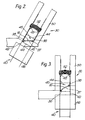
- Figure 2 is a schematic enlarged section taken along the line II-II of Figure 1
- Figure 3 is a similar view to Figure 2 of an alternative arrangement
- Figure 4 is a schematic view through the coil strip material being unwound in the apparatus of Figure 1
- Figures 5a-5d show different arrangements for guiding the ladders according to the invention.
- the assembly apparatus 10 illustrated in the drawings includes a main frame 12 on which is mounted a pay-off reel 14 of strip material 16, a crown forming unit 18 in which the strip is formed with an arcuate bow, and a strip accumulator 20.
- Strip in-feed equipment and its motor are indicated very schematically at 22 and this feeds the strip material 16 into a machine stand cabinet 24 having cutting and punching die-heads 26 which cut the strip slat forming material to the length of slat required, and punch holes in the slat material for the passage of lift cords.
- Out-feed motor 28 feeds the punched and cut slats through a number of assembly stations 30 in which the slats are interlaced into the ladders as will be described later.
- the ladders themselves can be moved longitudinally of the ladder side members by linear lift motors 32.
- Guides (not shown in Figure 1) on a lacing table 34 serve to guide the slat material fed by the out-feed motor 28 along a defined feed path.
- Figure 2 shows one of the assembly stations 30 according to the invention, in which slat material guides 36 are arranged to guide longitudinally the slat material 16 so that the plane 37 including the longitudinal sides 38 of the slat material extends horizontally.
- the ladder with which the slats are to be laced is indicated by the reference numeral 40 and includes longitudinal side cords or members 42 to transversely extending rungs 44.
- a ladder cord tensioning and guiding unit 46 in combination with some resilient supporting pawls 48 cause the side cords 42 to be tensioned and extend at an angle to the vertical and the cross rungs 44 are spaced apart to form an opening 45 which is generally rectangular.
- the plane 37 of the slat material is at an angle other than 90° to the direction of the side members 42 and is, therefore, extending approximately along a diagonal to the rectangular opening 45.
- the resilient supporting pawls 48 are mounted in slat holder guides 50, which are inclined at the same angle as the ladder cord side members 42 and serve to hold the assembled slats shown at 52, as the ladder is moved steadily up as a result of the in-feed of each successive slat. It will be appreciated that the slats themselves will become inclined so that they are parallel to the cross rungs 44 as a cross rung below the slant moves upwardly along the guide 50. Lifting means (not shown) are provided for this purpose, but are purely conventional other than the fact that they will be angled to move parallel to the guides 50.
- Figure 5 If one looks at Figure 5 the arrangement shown in Figure 2 is illustrated schematically in Figure 5a while that in Figure 3 is illustrated schematically in Figure 5d.
- Figure 5C while the side cords 42 of the ladder are inclined to the vertical, the cross rungs 44 are shown extending horizontally, so that the opening 45 is in the form of a parallelogram.
- the slat 16 is inclined to the horizontal and extends substantially across the longer diagonal of this parallelogram.
- Figure 5d the side cords 42 are inclined to the vertical and the cross rungs 44 are substantially perpendicular thereof, so that in this instance the slat material 16 is nearly vertical and extends across the opposite diagonal to that shown in Figure 5a.
- the "target" for the slat material is larger than it would be if it were parallel to the cross rungs 44.
- FIG 4 there is illustrated the reel 14 of coil strip material 16.
- the axis of the reel shaft 60 is shown inclined to the horizontal and a friction plate 62 is mounted with its plane perpendicular thereto by a holder 64, so that the coil strip material 16 rests under gravity against this plate 62.
- a friction plate 62 is mounted with its plane perpendicular thereto by a holder 64, so that the coil strip material 16 rests under gravity against this plate 62.
- the coiled strip material 16 As the coiled strip material 16 is unwound from the reel it will undergo friction with the plate and this will provide drag to the strip material the friction force producing this drag reducing as the weight of the coiled material reduces as it is unwound from the reel.
Landscapes
- Engineering & Computer Science (AREA)
- Structural Engineering (AREA)
- Architecture (AREA)
- Civil Engineering (AREA)
- Blinds (AREA)
- Physical Vapour Deposition (AREA)
- Formation And Processing Of Food Products (AREA)
- Crystals, And After-Treatments Of Crystals (AREA)
Abstract
Description
- The present invention relates to a method and apparatus for mechanically assembling a venetian blind.
- Venetian blinds consists of at least two ladders, either ladder cords or ladder tapes, each having laterally spaced side members and cross rungs defining openings to receive slats. The assembly can be done manually or by machine and in the latter case the ladders are intermittently fed lengthwise of the side members and are guided so that two adjacent rungs of each ladder and the portions of the longitudinal side members at the location of the two adjacent rungs are held apart, thereby to give a predetermined shape to the associated opening. The slat material is fed along a defined path through the openings.
- This works reasonably satisfactorily for slats having a width of 25 mm or more, but it has been found that it is difficult to achieve satisfactory results with narrower blinds, for example blinds having slats which are 16 mm wide. These slats themselves tend to be rather flimsy and the opening in the ladders into which they are to be introduced is relatively small. Furthermore, in order to cover a given window surface a much greater number of slats need to be inserted into the ladder. It will appreciated that the speed of the assembly machines is limited by the operation of the assembly work stations and the increase of speed which would be necessary to manufacture a blind to cover a given window space using these much narrower slats is not enhanced by the use of the smaller dimensions of the slats and the openings formed in the ladders.
- US-A-2532294 utilises spreading and supporting wings, which include V-shaped portions and ears about which the wings are pivotally mounted. The wings are swung to a position to deform the shape of the openings and at this moment the slats are inserted. Thereafter the slats tilt to lie on the rung below. The arrangement is rather cumbersome and can be unreliable in operation.
- According to the present invention the laterally spaced side members are spread apart such that the adjacent rungs are maintained at least substantially parallel to one another whereby the opening is a rectangle or parallelogram and in that the plane through the longitudinal sides of the slat material, as it is fed along said defined feed path, is positioned at an angle with respect to the adjacent cross-rungs so that it extends substantially along a diagonal of the associated opening.
- In this way, the slats can be fed generally diagonally through the openings so that there is a bigger "target" for the slat material to see as it is introduced into the relevent opening in the ladder.
- Reference is made above to the "longitudinal sides" of the slat material. Conventional slats are either flat sheet material or slightly arcuately bowed material. In this instance the longitudinal sides will be the longitudinal edges of the material. However, some venetian blinds have different cross sectional configurations, for example the slat material can be generally S-shaped in cross section. Here the longitudinal sides referred to above will be the lateral extremes of the slat material rather than the actual edges, which will then be inwardly of the longitudinal sides.
- The portions of the side members may be positioned at an angle to the vertical as the slat material is fed along the feed path and this in itself will ensure that the plane of the slat material is other than 90° to the length if this plane is itself horizontal. Alternatively, or additionally, the cross rungs can be positioned at an angle other than 90° to the said portions of the side members and/or the plane which passes through the longitudinal sides of the slat material, as it is fed along the defined feed path, can in itself be inclined to the horizontal.
- Where the plane of the slat material is itself horizontal, the slat material may be guided to the defined feed path from a reel of slat material, this reel having its axis inclined at an angle to the horizontal in the same sense as the angle at which the slat material is fed along the defined feed path. In this way the reel may be positioned to rest against the surface, so that the reel is braked by the friction surface, as it rotates upon the slat material being unwound therefrom. In this way as the material is unwound, the frictional force will progressively reduce to compensate the intermittent unreeling movement.
- Advantageously the angle which the plane of the slat material makes to the ladder side members is between 30° and 60°.
- The invention also provides an apparatus for mechanically assembling a venetian blind, said apparatus comprising means for feeding at least two ladders, each comprising longitudinal side members and cross rungs defining openings for the slats, the side members of each ladder being spaced by a predetermined spacing, intermittently along a direction lengthwise of said side members, a pair of side member guides for each ladder, the guides of a pair being spaced by said predetermined spacing to hold at least a portion of said side members apart, spreading means to hold apart two adjacent rungs opposite said portions of said side members to define the shape of the associated opening in each ladder, slat material feed means and slat material guides for feeding and guiding said slat material lengthwise along a defined path passing through said openings, characterised in that the side member guides are arranged parallel such as to spread the laterally spaced side members, such that the adjacent rungs are maintained at least substantially parallel to one another, whereby said opening is a rectangle or parallelogram and in that the side member guides are inclined at an angle to the plane including the longitudinal sides of the slat material as it is guided along said defined path by said slat material guides, so that it extends substantially along a diagonal of the associated opening.
- The side member guides may each extend at an angle to the vertical and/or the slat material guides are positioned so that the plane which includes the longitudinal sides of the slat material, as it is fed along the defined path, is inclined to the horizontal The spreading means may be separate spreading means or may simply comprise the side member guides for each ladder.
- In order that the present invention may more readily be understood, the following description is given, merely by way of example, reference being made to the accompanying drawings in which:-
Figure 1 is a schematic side elevation of one embodiment of a combined slat forming and assembly apparatus according to the invention;
Figure 2 is a schematic enlarged section taken along the line II-II of Figure 1;
Figure 3 is a similar view to Figure 2 of an alternative arrangement;
Figure 4 is a schematic view through the coil strip material being unwound in the apparatus of Figure 1; and
Figures 5a-5d show different arrangements for guiding the ladders according to the invention. - The
assembly apparatus 10 illustrated in the drawings includes amain frame 12 on which is mounted a pay-off reel 14 ofstrip material 16, acrown forming unit 18 in which the strip is formed with an arcuate bow, and astrip accumulator 20. Strip in-feed equipment and its motor are indicated very schematically at 22 and this feeds thestrip material 16 into amachine stand cabinet 24 having cutting and punching die-heads 26 which cut the strip slat forming material to the length of slat required, and punch holes in the slat material for the passage of lift cords. Out-feed motor 28 feeds the punched and cut slats through a number ofassembly stations 30 in which the slats are interlaced into the ladders as will be described later. The ladders themselves can be moved longitudinally of the ladder side members bylinear lift motors 32. Guides (not shown in Figure 1) on a lacing table 34 serve to guide the slat material fed by the out-feed motor 28 along a defined feed path. - The above described arrangement is substantially conventional and further detailed discussion is not deemed necessary here.
- Figure 2 shows one of the
assembly stations 30 according to the invention, in whichslat material guides 36 are arranged to guide longitudinally theslat material 16 so that theplane 37 including thelongitudinal sides 38 of the slat material extends horizontally. - The ladder with which the slats are to be laced is indicated by the
reference numeral 40 and includes longitudinal side cords ormembers 42 to transversely extendingrungs 44. It will be seen that a ladder cord tensioning and guidingunit 46 in combination with some resilient supportingpawls 48 cause theside cords 42 to be tensioned and extend at an angle to the vertical and thecross rungs 44 are spaced apart to form anopening 45 which is generally rectangular. With this arrangement, theplane 37 of the slat material is at an angle other than 90° to the direction of theside members 42 and is, therefore, extending approximately along a diagonal to therectangular opening 45. There is thus provided a much greater "target" for the slat material than if the plane of the slat material, as conventionally, were parallel to the cross rungs and perpendicular to the side members. - The resilient supporting
pawls 48 are mounted inslat holder guides 50, which are inclined at the same angle as the laddercord side members 42 and serve to hold the assembled slats shown at 52, as the ladder is moved steadily up as a result of the in-feed of each successive slat. It will be appreciated that the slats themselves will become inclined so that they are parallel to thecross rungs 44 as a cross rung below the slant moves upwardly along theguide 50. Lifting means (not shown) are provided for this purpose, but are purely conventional other than the fact that they will be angled to move parallel to theguides 50. - If reference is now made to Figure 3 a similar construction will be shown except that in this arrangement the
slat holder guides 50 and the ladder cord tensioning/guidingunit 46 are arranged to guide theside cords 42 of theladder 40 so that they extend in a vertical plane, and theslat guides 36 are arranged at an angle, so that theplane 37 is at an angle to the horizontal and therefore at an angle other than 90° to theside members 42 of the ladder. - If one looks at Figure 5 the arrangement shown in Figure 2 is illustrated schematically in Figure 5a while that in Figure 3 is illustrated schematically in Figure 5d. In Figure 5C while the
side cords 42 of the ladder are inclined to the vertical, thecross rungs 44 are shown extending horizontally, so that theopening 45 is in the form of a parallelogram. In this instance theslat 16 is inclined to the horizontal and extends substantially across the longer diagonal of this parallelogram. In Figure 5d theside cords 42 are inclined to the vertical and thecross rungs 44 are substantially perpendicular thereof, so that in this instance theslat material 16 is nearly vertical and extends across the opposite diagonal to that shown in Figure 5a. In all of these arrangements the "target" for the slat material is larger than it would be if it were parallel to thecross rungs 44. - In Figure 4 there is illustrated the
reel 14 ofcoil strip material 16. The axis of the reel shaft 60 is shown inclined to the horizontal and afriction plate 62 is mounted with its plane perpendicular thereto by aholder 64, so that thecoil strip material 16 rests under gravity against thisplate 62. As the coiledstrip material 16 is unwound from the reel it will undergo friction with the plate and this will provide drag to the strip material the friction force producing this drag reducing as the weight of the coiled material reduces as it is unwound from the reel.
Claims (12)
- A method of mechanically assembling a venetian blind, said method comprising the steps of providing at least two ladders (40), each having laterally spaced longitudinal side members (42) and cross rungs (44), defining openings (45) to receive successive lengths of slat material, intermittently feeding said ladders (40) lengthwise of said side members (42), while guiding said ladders so that two adjacent cross rungs of each ladder and portions of the longitudinal side members between said two adjacent cross rungs are held apart, thereby to give a predetermined shape to the associated opening (45), and feeding slat material (16) along a defined feed path (36) through said openings, characterised in that the laterally spaced side members (42) are spread apart such that the adjacent rungs (44) are maintained at least substantially parallel to one another whereby the opening is a rectangle or parallelogram and in that the plane (37) through the longitudinal sides (38) of the slat material (16), as it is fed along said defined feed path, is positioned at an angle with respect to the adjacent cross-rungs so that it extends substantially along a diagonal of the associated opening (45).
- A method according to claim 1, characterised in that said associated opening (45) has a parallelogram shape and in that said plane extends substantially along the longer diagonal of the parallelogram.
- A method according to claim 1 or 2, characterised in that the said portions of the side members (42) are positioned at an angle to the vertical as the slat material (16) is fed along said feed path.
- A method according to claim 1, 2 or 3, characterised in that said plane (37) through the longitudinal sides (38) of the slat material (16), as it is fed along said defined feed path (36), is inclined at an acute angle to the horizontal.
- A method according to claim 1, 2 or 3, characterised in that the plane (37) which passes through the longitudinal sides (38) of the slat material (16) is a horizontal plane as the material is fed along said defined feed path (36).
- A method according to claim 4, characterised in that the slat material (16) is guided to said defined feed path (36) from a reel (14) of slat material, said reel having its axis inclined at an angle to the horizontal in the same sense as the angle at which the slat material is fed along said defined feed path.
- A method according to claim 6, characterised in that the reel (14) is positioned to rest against a friction surface (62), so that said reel is braked by said friction surface, as it rotates upon the slat material being unwound therefrom.
- A method according to any preceding claim, characterised in that said angle is an acute angle, preferable between 30° and 60°.
- Apparatus for mechanically assembling a venetian blind, said apparatus comprising means (30) for feeding at least two ladders (40), each comprising longitudinal side members (42) and cross rungs (44) defining openings for the slats (16), the side members (42) of each ladder being spaced by a predetermined spacing, intermittently along a direction lengthwise of said side members, a pair of side member guides (46) for each ladder, the guides of a pair being spaced by said predetermined spacing to hold at least a portion of said side members apart, spreading means (46,48) to hold apart two adjacent rungs (44) opposite said portions of said side members to define the shape of the associated opening (45) in each ladder, slat material feed means (28) and slat material guides (36) for feeding and guiding said slat material lengthwise along a defined path passing through said openings (45), characterised in that the side member guides (46) are arranged parallel such as to spread the laterally spaced side members (42), such that the adjacent rungs (44) are maintained at least substantially parallel to one another, whereby said opening (45) is a rectangle or parallelogram and in that the side member guides (46) are inclined at an angle to the plane including the longitudinal sides (38) of the slat material (16) as it is guided along said defined path by said slat material guides (36), so that it extends substantially along a diagonal of the associated opening (45).
- Apparatus according to claim 9, characterised in that the side member guides each extend at an angle to the vertical.
- Apparatus according to claim 9 or 10, characterised in that said slat material guides are positioned so that the plane which includes the longitudinal sides of the slat material, as it is fed along said defined path, is inclined at an acute angle to the horizontal.
- Apparatus according to claim 9, 10 or 11, characterised in that the spreading means comprise the said side member guides for each ladder.
Priority Applications (6)
| Application Number | Priority Date | Filing Date | Title |
|---|---|---|---|
| EP87305425A EP0295346B1 (en) | 1987-06-18 | 1987-06-18 | A method and apparatus for mechanically assembling a venetian blind |
| DE8787305425T DE3770167D1 (en) | 1987-06-18 | 1987-06-18 | METHOD AND DEVICE FOR THE MECHANICAL PRODUCTION OF SHUTTERS. |
| AT87305425T ATE63602T1 (en) | 1987-06-18 | 1987-06-18 | METHOD AND DEVICE FOR MECHANICAL PRODUCTION OF BLINDS. |
| ES87305425T ES2022353B3 (en) | 1987-06-18 | 1987-06-18 | A METHOD AND APPARATUS FOR MECHANICALLY MOUNTING A VENETIAN BLIND |
| US07/383,767 US5099556A (en) | 1987-06-18 | 1989-07-24 | Method and apparatus for mechanically assembling a venetian blind |
| US07/618,771 US5127138A (en) | 1987-06-18 | 1990-11-27 | Method and apparatus for mechanically assembling a venetian blind |
Applications Claiming Priority (1)
| Application Number | Priority Date | Filing Date | Title |
|---|---|---|---|
| EP87305425A EP0295346B1 (en) | 1987-06-18 | 1987-06-18 | A method and apparatus for mechanically assembling a venetian blind |
Publications (2)
| Publication Number | Publication Date |
|---|---|
| EP0295346A1 EP0295346A1 (en) | 1988-12-21 |
| EP0295346B1 true EP0295346B1 (en) | 1991-05-15 |
Family
ID=8197949
Family Applications (1)
| Application Number | Title | Priority Date | Filing Date |
|---|---|---|---|
| EP87305425A Expired - Lifetime EP0295346B1 (en) | 1987-06-18 | 1987-06-18 | A method and apparatus for mechanically assembling a venetian blind |
Country Status (5)
| Country | Link |
|---|---|
| US (2) | US5099556A (en) |
| EP (1) | EP0295346B1 (en) |
| AT (1) | ATE63602T1 (en) |
| DE (1) | DE3770167D1 (en) |
| ES (1) | ES2022353B3 (en) |
Families Citing this family (7)
| Publication number | Priority date | Publication date | Assignee | Title |
|---|---|---|---|---|
| SE468401B (en) * | 1991-05-08 | 1993-01-11 | Sani Maskiner Ab | POWER MANUFACTURING MACHINE AND SHUTTING DEVICE FOR THIS |
| DK170180B1 (en) * | 1992-12-29 | 1995-06-06 | Fabers Fab As C | Process for manufacturing blinds for blinds as well as mechanism for use in the practice of the method |
| AU712085B2 (en) * | 1995-05-19 | 1999-10-28 | Hunter Douglas International N.V. | Method and apparatus for producing a plurality of sequentially arranged edge contoured slats |
| US5996198A (en) * | 1998-02-25 | 1999-12-07 | Wang; Cherng-Fa | Apparatus for ribbing cloth venetian blind strips |
| AU757340B2 (en) * | 1999-04-02 | 2003-02-20 | Hunter Douglas Industries Bv | Method and arrangement for automatic bow adjustment |
| JP3475186B2 (en) * | 2001-03-21 | 2003-12-08 | 株式会社ニチベイ | Blinds, blind slats, manufacturing method thereof and molding machine |
| US7464655B2 (en) * | 2006-01-12 | 2008-12-16 | Hunter Douglas Inc. | Apparatus for manufacturing fabric for coverings for architectural openings |
Family Cites Families (22)
| Publication number | Priority date | Publication date | Assignee | Title |
|---|---|---|---|---|
| CA490979A (en) * | 1953-03-03 | Hunter Douglas Corporation | Venetian blind | |
| DE220865C (en) * | ||||
| US1217603A (en) * | 1915-03-16 | 1917-02-27 | Marvin H Jester | Plaster-board-supporting metal clip. |
| US2532294A (en) * | 1949-02-10 | 1950-12-05 | Robert D Edwards | Machine for assembling venetian blinds |
| US2728108A (en) * | 1950-09-21 | 1955-12-27 | Jr Karl Frederick Schlegel | Method of making venetian blind ladder tape |
| US3281914A (en) * | 1964-08-21 | 1966-11-01 | Products Engineering Co | Method and apparatus for assembling venetian blinds |
| US3332188A (en) * | 1964-12-08 | 1967-07-25 | Otto W Schaefer | Plaster wall frame structure with stud securing clips |
| GB1114075A (en) * | 1966-07-28 | 1968-05-15 | Hunter Douglas International | Improvements in or relating to a method and apparatus for assembling venetian blinds |
| NL6701043A (en) * | 1967-01-23 | 1968-07-24 | ||
| NL6701042A (en) * | 1967-01-23 | 1968-07-24 | ||
| NL7013154A (en) * | 1970-09-04 | 1972-03-07 | ||
| DE2535453C2 (en) * | 1975-08-08 | 1986-12-11 | Hunter Douglas Industries B.V., Rotterdam | Device for finishing slatted blinds |
| US4053132A (en) * | 1976-08-05 | 1977-10-11 | James Anthony Del Pozzo | Shelf support |
| DE2644276C2 (en) * | 1976-09-30 | 1985-01-17 | Hunter Douglas Industries B.V., Rotterdam | Machine for assembling blinds that can be drawn up |
| CA1137730A (en) * | 1981-07-22 | 1982-12-21 | Agar (Robert S.) Inc. | Channel and cut-out structure for removeable partition wall |
| GB2124283B (en) * | 1982-07-16 | 1987-04-23 | Hunter Douglas Ind Bv | Slat feeding apparatus for venetian blind assembling machine |
| GB2124284B (en) * | 1982-07-23 | 1985-10-16 | Hunter Douglas Ind Bv | Assembling venetian blinds |
| GB2124285B (en) * | 1982-07-23 | 1985-10-02 | Hunter Douglas Ind Bv | Manufacturing venetian blinds |
| US4516300A (en) * | 1983-08-01 | 1985-05-14 | Hunter Douglas International N.V. | Apparatus and a method for assembling slats of a venetian blind |
| DE3328121A1 (en) * | 1983-08-04 | 1985-02-14 | Johann 4837 Verl Henkenjohann | Sunshade blind |
| US4543699A (en) * | 1983-11-14 | 1985-10-01 | Hunter Douglas Industries B.V. | Apparatus for assembling slatted venetian blinds |
| DD220865A1 (en) * | 1984-01-26 | 1985-04-10 | Orbitaplast Weissandt Goelzau | PROFILED JALOUSIELAMELLE |
-
1987
- 1987-06-18 EP EP87305425A patent/EP0295346B1/en not_active Expired - Lifetime
- 1987-06-18 ES ES87305425T patent/ES2022353B3/en not_active Expired - Lifetime
- 1987-06-18 AT AT87305425T patent/ATE63602T1/en not_active IP Right Cessation
- 1987-06-18 DE DE8787305425T patent/DE3770167D1/en not_active Expired - Fee Related
-
1989
- 1989-07-24 US US07/383,767 patent/US5099556A/en not_active Expired - Fee Related
-
1990
- 1990-11-27 US US07/618,771 patent/US5127138A/en not_active Expired - Fee Related
Also Published As
| Publication number | Publication date |
|---|---|
| US5127138A (en) | 1992-07-07 |
| US5099556A (en) | 1992-03-31 |
| EP0295346A1 (en) | 1988-12-21 |
| DE3770167D1 (en) | 1991-06-20 |
| ES2022353B3 (en) | 1991-12-01 |
| ATE63602T1 (en) | 1991-06-15 |
Similar Documents
| Publication | Publication Date | Title |
|---|---|---|
| US4639987A (en) | Apparatus for producing simultaneously a plurality of Venetian blinds | |
| CA1068083A (en) | Method and apparatus for assembling venetian blind slats | |
| US5127138A (en) | Method and apparatus for mechanically assembling a venetian blind | |
| EP0133759B1 (en) | Apparatus and a method for assembling slats of a venetian blind | |
| EP0100154B1 (en) | Unit for positioning a venetian blind ladder and for guiding the slats of the blind thereonto | |
| US4958421A (en) | Method for assembling a venetian blind | |
| AU580996B2 (en) | Machine for the production of venetian blinds | |
| US4543699A (en) | Apparatus for assembling slatted venetian blinds | |
| US2103394A (en) | Venetian blind | |
| US3824657A (en) | Guiding device in a machine for manufacturing venetian blinds | |
| US3043178A (en) | Machine for punching venetian blind head bars | |
| US6443042B1 (en) | Method and apparatus for manufacturing a wood blind | |
| GB1200545A (en) | Universal assembling machine for the manufacture of stacks of slats for venetian blinds | |
| CN211993150U (en) | Cutting device | |
| US6233800B1 (en) | Venetian blind lacing station | |
| EP0297759B1 (en) | Venetian blind assembly method and apparatus | |
| EP0297183B1 (en) | Apparatus for mechanically assembling a venetian blind | |
| US2593048A (en) | Venetian blind headbar construction | |
| US2703447A (en) | Cord and tape cutter and method | |
| KR970067416A (en) | A method of attaching one or more strings or tapes of metallic material onto a sheet, a mechanism for carrying out the method, a plate comprising one or more strings or tapes, and a reel of such a plate | |
| GB1114075A (en) | Improvements in or relating to a method and apparatus for assembling venetian blinds | |
| CA1062117A (en) | Microfilm jacket micro film feeding device and process | |
| WO2024117966A1 (en) | A device for resizing a window covering arrangement | |
| DE2238177A1 (en) | LAMELLA CURTAIN |
Legal Events
| Date | Code | Title | Description |
|---|---|---|---|
| PUAI | Public reference made under article 153(3) epc to a published international application that has entered the european phase |
Free format text: ORIGINAL CODE: 0009012 |
|
| AK | Designated contracting states |
Kind code of ref document: A1 Designated state(s): AT BE CH DE ES FR GB GR IT LI LU NL SE |
|
| 17P | Request for examination filed |
Effective date: 19890412 |
|
| 17Q | First examination report despatched |
Effective date: 19891219 |
|
| GRAA | (expected) grant |
Free format text: ORIGINAL CODE: 0009210 |
|
| AK | Designated contracting states |
Kind code of ref document: B1 Designated state(s): AT BE CH DE ES FR GB GR IT LI LU NL SE |
|
| PG25 | Lapsed in a contracting state [announced via postgrant information from national office to epo] |
Ref country code: LI Effective date: 19910515 Ref country code: GR Free format text: LAPSE BECAUSE OF FAILURE TO SUBMIT A TRANSLATION OF THE DESCRIPTION OR TO PAY THE FEE WITHIN THE PRESCRIBED TIME-LIMIT Effective date: 19910515 Ref country code: CH Effective date: 19910515 Ref country code: BE Effective date: 19910515 |
|
| REF | Corresponds to: |
Ref document number: 63602 Country of ref document: AT Date of ref document: 19910615 Kind code of ref document: T |
|
| REF | Corresponds to: |
Ref document number: 3770167 Country of ref document: DE Date of ref document: 19910620 |
|
| ITF | It: translation for a ep patent filed | ||
| ET | Fr: translation filed | ||
| PG25 | Lapsed in a contracting state [announced via postgrant information from national office to epo] |
Ref country code: LU Free format text: LAPSE BECAUSE OF NON-PAYMENT OF DUE FEES Effective date: 19910630 |
|
| REG | Reference to a national code |
Ref country code: CH Ref legal event code: PL |
|
| PLBE | No opposition filed within time limit |
Free format text: ORIGINAL CODE: 0009261 |
|
| STAA | Information on the status of an ep patent application or granted ep patent |
Free format text: STATUS: NO OPPOSITION FILED WITHIN TIME LIMIT |
|
| 26N | No opposition filed | ||
| PGFP | Annual fee paid to national office [announced via postgrant information from national office to epo] |
Ref country code: AT Payment date: 19930614 Year of fee payment: 7 |
|
| PG25 | Lapsed in a contracting state [announced via postgrant information from national office to epo] |
Ref country code: AT Effective date: 19940618 |
|
| EAL | Se: european patent in force in sweden |
Ref document number: 87305425.8 |
|
| PGFP | Annual fee paid to national office [announced via postgrant information from national office to epo] |
Ref country code: SE Payment date: 19950515 Year of fee payment: 9 |
|
| PGFP | Annual fee paid to national office [announced via postgrant information from national office to epo] |
Ref country code: NL Payment date: 19950531 Year of fee payment: 9 |
|
| PGFP | Annual fee paid to national office [announced via postgrant information from national office to epo] |
Ref country code: GB Payment date: 19950607 Year of fee payment: 9 |
|
| PGFP | Annual fee paid to national office [announced via postgrant information from national office to epo] |
Ref country code: FR Payment date: 19950609 Year of fee payment: 9 |
|
| PGFP | Annual fee paid to national office [announced via postgrant information from national office to epo] |
Ref country code: ES Payment date: 19950628 Year of fee payment: 9 |
|
| PG25 | Lapsed in a contracting state [announced via postgrant information from national office to epo] |
Ref country code: GB Effective date: 19960618 |
|
| PG25 | Lapsed in a contracting state [announced via postgrant information from national office to epo] |
Ref country code: SE Effective date: 19960619 Ref country code: ES Free format text: LAPSE BECAUSE OF EXPIRATION OF PROTECTION Effective date: 19960619 |
|
| PG25 | Lapsed in a contracting state [announced via postgrant information from national office to epo] |
Ref country code: NL Effective date: 19970101 |
|
| GBPC | Gb: european patent ceased through non-payment of renewal fee |
Effective date: 19960618 |
|
| PG25 | Lapsed in a contracting state [announced via postgrant information from national office to epo] |
Ref country code: FR Effective date: 19970228 |
|
| EUG | Se: european patent has lapsed |
Ref document number: 87305425.8 |
|
| NLV4 | Nl: lapsed or anulled due to non-payment of the annual fee |
Effective date: 19970101 |
|
| REG | Reference to a national code |
Ref country code: FR Ref legal event code: ST |
|
| PGFP | Annual fee paid to national office [announced via postgrant information from national office to epo] |
Ref country code: DE Payment date: 19980629 Year of fee payment: 12 |
|
| REG | Reference to a national code |
Ref country code: ES Ref legal event code: FD2A Effective date: 19990601 |
|
| PG25 | Lapsed in a contracting state [announced via postgrant information from national office to epo] |
Ref country code: DE Free format text: LAPSE BECAUSE OF NON-PAYMENT OF DUE FEES Effective date: 20000503 |
|
| PG25 | Lapsed in a contracting state [announced via postgrant information from national office to epo] |
Ref country code: IT Free format text: LAPSE BECAUSE OF NON-PAYMENT OF DUE FEES;WARNING: LAPSES OF ITALIAN PATENTS WITH EFFECTIVE DATE BEFORE 2007 MAY HAVE OCCURRED AT ANY TIME BEFORE 2007. THE CORRECT EFFECTIVE DATE MAY BE DIFFERENT FROM THE ONE RECORDED. Effective date: 20050618 |