EP0295223B1 - Roller door - Google Patents
Roller door Download PDFInfo
- Publication number
- EP0295223B1 EP0295223B1 EP88830253A EP88830253A EP0295223B1 EP 0295223 B1 EP0295223 B1 EP 0295223B1 EP 88830253 A EP88830253 A EP 88830253A EP 88830253 A EP88830253 A EP 88830253A EP 0295223 B1 EP0295223 B1 EP 0295223B1
- Authority
- EP
- European Patent Office
- Prior art keywords
- panel
- spring
- balancing
- bracket
- cross member
- Prior art date
- Legal status (The legal status is an assumption and is not a legal conclusion. Google has not performed a legal analysis and makes no representation as to the accuracy of the status listed.)
- Expired - Lifetime
Links
Images


Classifications
-
- E—FIXED CONSTRUCTIONS
- E06—DOORS, WINDOWS, SHUTTERS, OR ROLLER BLINDS IN GENERAL; LADDERS
- E06B—FIXED OR MOVABLE CLOSURES FOR OPENINGS IN BUILDINGS, VEHICLES, FENCES OR LIKE ENCLOSURES IN GENERAL, e.g. DOORS, WINDOWS, BLINDS, GATES
- E06B9/00—Screening or protective devices for wall or similar openings, with or without operating or securing mechanisms; Closures of similar construction
- E06B9/56—Operating, guiding or securing devices or arrangements for roll-type closures; Spring drums; Tape drums; Counterweighting arrangements therefor
- E06B9/68—Operating devices or mechanisms, e.g. with electric drive
-
- E—FIXED CONSTRUCTIONS
- E06—DOORS, WINDOWS, SHUTTERS, OR ROLLER BLINDS IN GENERAL; LADDERS
- E06B—FIXED OR MOVABLE CLOSURES FOR OPENINGS IN BUILDINGS, VEHICLES, FENCES OR LIKE ENCLOSURES IN GENERAL, e.g. DOORS, WINDOWS, BLINDS, GATES
- E06B9/00—Screening or protective devices for wall or similar openings, with or without operating or securing mechanisms; Closures of similar construction
- E06B9/56—Operating, guiding or securing devices or arrangements for roll-type closures; Spring drums; Tape drums; Counterweighting arrangements therefor
- E06B9/62—Counterweighting arrangements
Definitions
- the present invention relates to a roller door including a flexible panel provided with a cross member at its free end, a roller onto which the panel is wound, two vertical guide frames provided with facing vertical slots in which the ends of the cross member are engaged, means for balancing the weight of the panel, and means for keeping the panel under tension vertically.
- a roller door of the above type is known from the published European application EP-A-144,893 and includes balancing torsion springs housed in the upper horizontal roller onto which the panel is wound and tensioning torsion springs arranged at the sides of the roller, which tension the panel by means of lateral vertical cables and pulleys fixed to the ground.
- a roller door of the above type is known from the patent US-A-3,878,879 and uses, on each of the two sides of the door, a closed system constituted by a cable which connects the free end of the panel to a roller fast with the roller onto which the panel is wound and passes over two fixed pulleys and a vertically movable pulley subject to the action of a counterweight.
- This closed system simultaneously fulfils the functions of balancing the weight of the panel and of tensioning the panel itself.
- EP-A-125.217 describes a variant of the system known from the aforementioned patent US-A-3,878,879, in which the counterweight acting on the vertically movable pulley is replaced by a helical spring working under tension.
- a belt or cable which passes over two lower fixed return pulleys, over the upper surface of a pulley mounted rotatably on an upper fixed bracket and over the under surface of a vertically movable pulley, rotatably mounted on a bracket which is connected to a fixed point at the base of the frame by a tensioning spring, the opposite end of each of said belts or cables being wound onto a disc which is mounted on the same shaft as the roll-up roller.
- the force of said tensioning spring is divided into two vertical components, one of which is transferred to the panel as a downwardly directed force which fulfills the function of tensioning the panel and the other of which is transferred to the panel as an upwardly directed force which fulfills the function of balancing the weight of the panel itself.
- the subject of the present invention is a roller door of the type specified above having the features claimed in claim 1.
- the flexible panel for example of plastics material, of a roller door is indicated 1.
- the panel winds onto a winding roller 2 whose shaft 3 is supported rotatably in the upper structure of the door, indicated 4.
- the shaft 3 is rotated by an electric motor M through a transmission 5.
- An electromagnetic brake 6 associated with the motor M is released when the motor is supplied and engaged under the action of a spring when there is no supply to the motor.
- a lever control (not illustrated) enables the above brake to be released in an emergency, to enable free rotation of the shaft 3.
- the free end of the panel 1 carries a cross member 7 whose ends are engaged in guide slots formed in two vertical frames 8 which support the upper structure 4.
- a rubber protective device 9 Associated with the cross member 7 is a rubber protective device 9 serving to reverse the sense of rotation of the motor M in the event of the cross member encountering an obstacle during the closing of the door.
- a cable 10 which passes, within the respective frame 8, over two lower return pulleys 11, 12 rotatably supported at the base of each vertical frame 8, and which is wound, in the sense opposite the sense of the winding of the panel 1, onto an upper vertically movable pulley 13 connected with the interposition of a helical tensioning spring 14 working under tension, to a fixed point 15 at the base of the frame.
- the pulley 13 is supported rotatably by a bracket 16 supported by a belt 17 whose folded end is gripped by a clamp 18.
- the belt 17 (which could also be replaced by a cable) is wound onto the shaft 3 of the roller 2 in the sense opposite the sense of winding of the panel.
- the belt 17 could be wound onto a pulley fixed to the shaft.
- the bracket 16 is connected at its lower end to a helical balancing spring 19 working under tension, the lower end of which is connected to a fixed point 20 at the base of the frame 8.
- the spring 19 is preferably dimensioned so as to exert on the shaft of the roller 2 a moment greater than that exerted by the weight of the panel 1 in a clockwise sense when the door is in the closed position.
- the device described above enables a correct and constant balancing of the weight of the panel 1 and its cross member 7 to be achieved as a result of the variations in the diameters of winding of the panel 1 on the roller 2 and of the belt or cable 17 on the shaft 3 which occur as the door moves from the open position to the closed position. Moreover, it enables the desired tensioning of the panel to be achieved when the door is closed.
- the lower end of the bracket 16 carries a cross member 20a inserted between the upper coils of the spring 19.
- a possible counterweight fixed to the base of the bracket 16 and housed within the balancing spring 19 is indicated 21.
- the above-described device for connection between the bracket 16 and the balancing spring 19 enables the tension of the spring to be adjusted easily from the ground. In fact, after the disengagement of the clamp 18 to detach the belt 17 from the bracket 16, it is only necessary to rotate the bracket to vary its axial position relative to the spring 19.
- the tension of the tensioning spring 14 can also be adjusted easily with the use of a known axially adjustable attachment device for connecting this spring to the cable 10.
- the above-described system enables extremely quick, simple and effortless manual operation in an emergency; in fact, it suffices manually to release the brake coupled to the electric motor M, since the closed door opens automatically up to its maximum height due to the prevalence of the moment exerted by the spring 19 over the moment exerted by the weight of the panel 1.
- the device for adjusting the tension in the balancing spring 19 differs from that described with reference to Figure 5 in that a cross member 20a provided with two holes 22 at its ends, through which the upper coil of the spring 19 is passed, is fixed to the base of the bracket 16.
- the adjustment of the tension of the spring 19 is also achieved by rotation of the cross member 20a relative to the spring after the removal of the clamp 18, which must be fixed again after adjustment.
- the variant illustrated in Figures 7 and 8 differs from that illustrated in Figures 3 and 4 in that the cable 10 passes over a single return pulley 23 at the bottom and is wound onto the movable pulley 16 in the sense opposite the sense of winding of the panel.
- the tensioning spring 14 housed in each of the two vertical structures 8 is situated on the side of the panel 1 opposite the balancing spring 19, instead of being between the panel 1 and the spring 19 as in the embodiment described above.
- the bracket 116 is in the form of a hollow body comprising two containers 25 which are side by side and support the pulley 13 between them.
- the lower parts of the containers 25 contain lead which is introduced by casting and forms the counterweight 24.
- Loose metallic material can be added to the upper parts of the containers 25 to adjust the balancing.
Landscapes
- Engineering & Computer Science (AREA)
- Structural Engineering (AREA)
- Architecture (AREA)
- Civil Engineering (AREA)
- Power-Operated Mechanisms For Wings (AREA)
- Gates (AREA)
- Closing And Opening Devices For Wings, And Checks For Wings (AREA)
- Lift-Guide Devices, And Elevator Ropes And Cables (AREA)
- Devices For Conveying Motion By Means Of Endless Flexible Members (AREA)
- Window Of Vehicle (AREA)
- Support Devices For Sliding Doors (AREA)
- Rolls And Other Rotary Bodies (AREA)
- Power Steering Mechanism (AREA)
- Lock And Its Accessories (AREA)
Abstract
Description
- The present invention relates to a roller door including a flexible panel provided with a cross member at its free end, a roller onto which the panel is wound, two vertical guide frames provided with facing vertical slots in which the ends of the cross member are engaged, means for balancing the weight of the panel, and means for keeping the panel under tension vertically.
- A roller door of the above type is known from the published European application EP-A-144,893 and includes balancing torsion springs housed in the upper horizontal roller onto which the panel is wound and tensioning torsion springs arranged at the sides of the roller, which tension the panel by means of lateral vertical cables and pulleys fixed to the ground.
- Since helical torsion springs have much greater diameters than helical tension springs with the same performance, this solution requires shafts of very large dimensions and does not permit the production of large doors. Moreover, this solution involves difficulties in the carrying out of maintenance and adjustment of the springs, which are not situated in easily accessible positions.
- A roller door of the above type is known from the patent US-A-3,878,879 and uses, on each of the two sides of the door, a closed system constituted by a cable which connects the free end of the panel to a roller fast with the roller onto which the panel is wound and passes over two fixed pulleys and a vertically movable pulley subject to the action of a counterweight.
- This closed system simultaneously fulfils the functions of balancing the weight of the panel and of tensioning the panel itself.
- This system has the disadvantage that adjustment of the balancing necessarily involves an undesirable simultaneous variation of the tensioning.
- Published European patent application EP-A-125.217 describes a variant of the system known from the aforementioned patent US-A-3,878,879, in which the counterweight acting on the vertically movable pulley is replaced by a helical spring working under tension. In the roller door disclosed in EP-A-125.217 to each of the ends of the cross member is connected a belt or cable which passes over two lower fixed return pulleys, over the upper surface of a pulley mounted rotatably on an upper fixed bracket and over the under surface of a vertically movable pulley, rotatably mounted on a bracket which is connected to a fixed point at the base of the frame by a tensioning spring, the opposite end of each of said belts or cables being wound onto a disc which is mounted on the same shaft as the roll-up roller.
- The force of said tensioning spring is divided into two vertical components, one of which is transferred to the panel as a downwardly directed force which fulfills the function of tensioning the panel and the other of which is transferred to the panel as an upwardly directed force which fulfills the function of balancing the weight of the panel itself.
- In case of large doors, a second cable is added which is wound onto a roller fast with the roller onto which the panel is wound and having a larger diameter than the latter, passes over pulleys, and is subject to the action of a counterweight having the function of increasing the balancing of the weight of the panel. As well as the disadvantages indicated above, this system has more complicated and expensive structure.
- In order to avoid the problems of the aforementioned known solution, the subject of the present invention is a roller door of the type specified above having the features claimed in
claim 1. - Further characteristics and advantages of the present invention will become clear from the description which follows with reference to the appended drawings, provided purely by way of non-limiting example, in which:
- Figure 1 is a partially-sectioned schematic front view of a roller door according to the invention,
- Figure 2 is a schematic plan view of Figure 1,
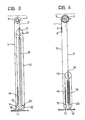
- Figure 3 is a partial section taken on the line 3-3 of Figure 1,
- Figure 4 is a view similar to Figure 3 with the door in the open condition,
- Figure 5 is a perspective detail of the device for adjusting the tension of the balancing spring,
- Figure 6 is a variant of Figure 5,
- Figures 7 and 8 show a variant of the invention in views similar to those of Figures 3 and 4,
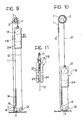
- Figures 9 and 10 are views similar to Figure 3 and 4 of a further variant, and
- Figure 11 is a partially-sectioned partial side view of the part indicated by the arrow XI in Figure 9.
- In the embodiment illustrated in Figures 1 to 5, the flexible panel, for example of plastics material, of a roller door is indicated 1.
- The panel winds onto a
winding roller 2 whoseshaft 3 is supported rotatably in the upper structure of the door, indicated 4. - The
shaft 3 is rotated by an electric motor M through atransmission 5. - An
electromagnetic brake 6 associated with the motor M is released when the motor is supplied and engaged under the action of a spring when there is no supply to the motor. - A lever control (not illustrated) enables the above brake to be released in an emergency, to enable free rotation of the
shaft 3. - The free end of the
panel 1 carries across member 7 whose ends are engaged in guide slots formed in twovertical frames 8 which support the upper structure 4. - Associated with the
cross member 7 is a rubber protective device 9 serving to reverse the sense of rotation of the motor M in the event of the cross member encountering an obstacle during the closing of the door. - Connected to each of the two ends of the
cross member 7 is acable 10 which passes, within therespective frame 8, over twolower return pulleys vertical frame 8, and which is wound, in the sense opposite the sense of the winding of thepanel 1, onto an upper verticallymovable pulley 13 connected with the interposition of ahelical tensioning spring 14 working under tension, to afixed point 15 at the base of the frame. - The
pulley 13 is supported rotatably by abracket 16 supported by abelt 17 whose folded end is gripped by aclamp 18. - The belt 17 (which could also be replaced by a cable) is wound onto the
shaft 3 of theroller 2 in the sense opposite the sense of winding of the panel. Clearly, instead of being wound directly onto theshaft 3, thebelt 17 could be wound onto a pulley fixed to the shaft. - The
bracket 16 is connected at its lower end to ahelical balancing spring 19 working under tension, the lower end of which is connected to afixed point 20 at the base of theframe 8. - The
spring 19 is preferably dimensioned so as to exert on the shaft of the roller 2 a moment greater than that exerted by the weight of thepanel 1 in a clockwise sense when the door is in the closed position. - The device described above enables a correct and constant balancing of the weight of the
panel 1 and itscross member 7 to be achieved as a result of the variations in the diameters of winding of thepanel 1 on theroller 2 and of the belt orcable 17 on theshaft 3 which occur as the door moves from the open position to the closed position. Moreover, it enables the desired tensioning of the panel to be achieved when the door is closed. - As illustrated in Figure 5, the lower end of the
bracket 16 carries across member 20a inserted between the upper coils of thespring 19. - A possible counterweight fixed to the base of the
bracket 16 and housed within the balancingspring 19 is indicated 21. - The above-described device for connection between the
bracket 16 and the balancingspring 19 enables the tension of the spring to be adjusted easily from the ground. In fact, after the disengagement of theclamp 18 to detach thebelt 17 from thebracket 16, it is only necessary to rotate the bracket to vary its axial position relative to thespring 19. - The tension of the tensioning
spring 14 can also be adjusted easily with the use of a known axially adjustable attachment device for connecting this spring to thecable 10. - It is thus possible easily to adjust the tension of the balancing
springs 19 housed in thevertical frames 8 in the event that the characteristics of these springs undergo variations with time, and to adjust the tension in thetensioning springs 14 according to the wind strength. - Furthermore, the above-described system enables extremely quick, simple and effortless manual operation in an emergency; in fact, it suffices manually to release the brake coupled to the electric motor M, since the closed door opens automatically up to its maximum height due to the prevalence of the moment exerted by the
spring 19 over the moment exerted by the weight of thepanel 1. - In the embodiment shown in Figure 6, the device for adjusting the tension in the balancing
spring 19 differs from that described with reference to Figure 5 in that across member 20a provided with twoholes 22 at its ends, through which the upper coil of thespring 19 is passed, is fixed to the base of thebracket 16. In this case, the adjustment of the tension of thespring 19 is also achieved by rotation of thecross member 20a relative to the spring after the removal of theclamp 18, which must be fixed again after adjustment. - The variant illustrated in Figures 7 and 8 differs from that illustrated in Figures 3 and 4 in that the
cable 10 passes over asingle return pulley 23 at the bottom and is wound onto themovable pulley 16 in the sense opposite the sense of winding of the panel. In this case, thetensioning spring 14 housed in each of the twovertical structures 8 is situated on the side of thepanel 1 opposite the balancingspring 19, instead of being between thepanel 1 and thespring 19 as in the embodiment described above. - The variant illustrated in Figures 9 to 11 differs from the embodiment of Figures 3 and 4 in that the
spring 19 for balancing the weight of the panel has been replaced by acounterweight 24 fixed to the bracket, indicated 116, which is supported by thebelt 17 and carries theupper return pulley 13 for thecable 10. - As shown in Figure 11, the
bracket 116 is in the form of a hollow body comprising twocontainers 25 which are side by side and support thepulley 13 between them. The lower parts of thecontainers 25 contain lead which is introduced by casting and forms thecounterweight 24. Loose metallic material can be added to the upper parts of thecontainers 25 to adjust the balancing.
Claims (10)
Priority Applications (1)
| Application Number | Priority Date | Filing Date | Title |
|---|---|---|---|
| AT88830253T ATE67272T1 (en) | 1987-06-12 | 1988-06-07 | ROLLING GATE. |
Applications Claiming Priority (2)
| Application Number | Priority Date | Filing Date | Title |
|---|---|---|---|
| IT8767506A IT1210793B (en) | 1987-06-12 | 1987-06-12 | ROLLING DOOR |
| IT6750687 | 1987-06-12 |
Publications (2)
| Publication Number | Publication Date |
|---|---|
| EP0295223A1 EP0295223A1 (en) | 1988-12-14 |
| EP0295223B1 true EP0295223B1 (en) | 1991-09-11 |
Family
ID=11302992
Family Applications (1)
| Application Number | Title | Priority Date | Filing Date |
|---|---|---|---|
| EP88830253A Expired - Lifetime EP0295223B1 (en) | 1987-06-12 | 1988-06-07 | Roller door |
Country Status (6)
| Country | Link |
|---|---|
| EP (1) | EP0295223B1 (en) |
| AT (1) | ATE67272T1 (en) |
| DE (1) | DE3864753D1 (en) |
| ES (1) | ES2025814T3 (en) |
| GR (1) | GR3002728T3 (en) |
| IT (1) | IT1210793B (en) |
Families Citing this family (5)
| Publication number | Priority date | Publication date | Assignee | Title |
|---|---|---|---|---|
| DE4005963A1 (en) * | 1989-03-03 | 1990-09-06 | Itw Ind Und Werkzeugmaschinen | Suspension system for roller blind-type door - has winding roller with cable and pulley systems incorporating resilient tensioning devices |
| DE10011789A1 (en) * | 2000-03-13 | 2001-09-20 | Aktor Ind Gmbh | Roller door with door panel windable to multi-layered configuration comprises several fixed lamellas covering over width of door aperture and moving in vertical guide tracks |
| DE60308049T2 (en) | 2002-10-18 | 2006-12-14 | Dentsply International Inc. | Double-thread dynamometer for measuring the performance of a dental handpiece at high speed and low torque |
| US9250160B2 (en) | 2013-03-15 | 2016-02-02 | American Dental Association | Method and apparatus for characterizing handpieces |
| CN108533162B (en) * | 2018-05-24 | 2020-02-21 | 张集文 | Up-down freely opening and closing roller shutter |
Family Cites Families (5)
| Publication number | Priority date | Publication date | Assignee | Title |
|---|---|---|---|---|
| US2543711A (en) * | 1947-07-02 | 1951-02-27 | Schultz Abraham | Closure operator |
| FR2181601B1 (en) * | 1972-04-24 | 1974-12-20 | Ressorts Francais | |
| AT341177B (en) * | 1975-10-13 | 1978-01-25 | Lindpointner Ludwig | ROLLING DOOR OD.DGL. |
| DE3245009A1 (en) * | 1982-12-06 | 1984-06-14 | Adolf Seuster GmbH, 5880 Lüdenscheid | Roller door |
| SE8300573L (en) * | 1983-02-03 | 1984-08-04 | Nordiskafilt Ab | roller door |
-
1987
- 1987-06-12 IT IT8767506A patent/IT1210793B/en active
-
1988
- 1988-06-07 DE DE8888830253T patent/DE3864753D1/en not_active Expired - Fee Related
- 1988-06-07 ES ES198888830253T patent/ES2025814T3/en not_active Expired - Lifetime
- 1988-06-07 AT AT88830253T patent/ATE67272T1/en not_active IP Right Cessation
- 1988-06-07 EP EP88830253A patent/EP0295223B1/en not_active Expired - Lifetime
-
1991
- 1991-09-16 GR GR91401343T patent/GR3002728T3/en unknown
Also Published As
| Publication number | Publication date |
|---|---|
| EP0295223A1 (en) | 1988-12-14 |
| GR3002728T3 (en) | 1993-01-25 |
| ES2025814T3 (en) | 1992-04-01 |
| ATE67272T1 (en) | 1991-09-15 |
| IT1210793B (en) | 1989-09-20 |
| DE3864753D1 (en) | 1991-10-17 |
| IT8767506A0 (en) | 1987-06-12 |
Similar Documents
| Publication | Publication Date | Title |
|---|---|---|
| US4697630A (en) | Tilt mechanism for venetian blinds | |
| US5048588A (en) | Roll-up door construction | |
| NL9202268A (en) | INDUSTRIAL ROLLING DOOR WITH A COMBINED BELT FOR THE COUNTERWEIGHT AND SPRING TENSION BELT. | |
| EP0295223B1 (en) | Roller door | |
| WO1998051899A1 (en) | Roll-up door | |
| US1944772A (en) | Elevator compensating rope sheave | |
| CA2160830A1 (en) | Safety brake for an elevator | |
| SE9001179A (en) | ||
| EP0697990B1 (en) | Creel | |
| CN116924140A (en) | Cable adjusting device and bracket | |
| CN110723603B (en) | Airborne take-up and pay-off device of unmanned aerial vehicle | |
| CA1052351A (en) | Strand carrier for a strand fabricating machine | |
| CN209740430U (en) | Cable damping structure for mooring take-up and pay-off line of unmanned aerial vehicle | |
| CA2092795A1 (en) | Balancing device for a raisable-curtain goods-handling door | |
| EP0987072B1 (en) | Traction device for use in the manufacturing process of ornamental chains | |
| US5186285A (en) | Method of, and a device for, controlling the rotation of an element about an axis by means of a wrap spring | |
| US2232993A (en) | Wire drawing machine | |
| CN212798818U (en) | Unreeling machine accessory | |
| EP0632182B1 (en) | Operating unit for up-and-over doors | |
| CN211644232U (en) | Safety elevator overspeed governor overspeed device tensioner | |
| CN216937762U (en) | Winding device of high-carbon copper-plated spring steel wire for automotive interior system | |
| JPH0750556Y2 (en) | Screen winding mechanism | |
| CN217376740U (en) | Closed loop feedback type tension control mechanism and winding device | |
| CN220785416U (en) | Wire wheel type electric sunshade screen movement abnormality monitoring system | |
| GB2205355A (en) | Improvements in or relating to door operators |
Legal Events
| Date | Code | Title | Description |
|---|---|---|---|
| PUAI | Public reference made under article 153(3) epc to a published international application that has entered the european phase |
Free format text: ORIGINAL CODE: 0009012 |
|
| AK | Designated contracting states |
Kind code of ref document: A1 Designated state(s): AT BE CH DE ES FR GB GR IT LI LU NL SE |
|
| 17P | Request for examination filed |
Effective date: 19890527 |
|
| 17Q | First examination report despatched |
Effective date: 19900212 |
|
| GRAA | (expected) grant |
Free format text: ORIGINAL CODE: 0009210 |
|
| AK | Designated contracting states |
Kind code of ref document: B1 Designated state(s): AT BE CH DE ES FR GB GR IT LI LU NL SE |
|
| PG25 | Lapsed in a contracting state [announced via postgrant information from national office to epo] |
Ref country code: IT Free format text: LAPSE BECAUSE OF FAILURE TO SUBMIT A TRANSLATION OF THE DESCRIPTION OR TO PAY THE FEE WITHIN THE PRE;WARNING: LAPSES OF ITALIAN PATENTS WITH EFFECTIVE DATE BEFORE 2007 MAY HAVE OCCURRED AT ANY TIME BEFORE 2007. THE CORRECT EFFECTIVE DATE MAY BE DIFFERENT FROM THE ONE RECORDED.SCRIBED TIME-LIMIT Effective date: 19910911 Ref country code: SE Effective date: 19910911 Ref country code: AT Effective date: 19910911 Ref country code: NL Effective date: 19910911 |
|
| REF | Corresponds to: |
Ref document number: 67272 Country of ref document: AT Date of ref document: 19910915 Kind code of ref document: T |
|
| REF | Corresponds to: |
Ref document number: 3864753 Country of ref document: DE Date of ref document: 19911017 |
|
| ET | Fr: translation filed | ||
| NLV1 | Nl: lapsed or annulled due to failure to fulfill the requirements of art. 29p and 29m of the patents act | ||
| REG | Reference to a national code |
Ref country code: ES Ref legal event code: FG2A Ref document number: 2025814 Country of ref document: ES Kind code of ref document: T3 |
|
| PG25 | Lapsed in a contracting state [announced via postgrant information from national office to epo] |
Ref country code: LU Free format text: LAPSE BECAUSE OF NON-PAYMENT OF DUE FEES Effective date: 19920630 |
|
| PLBE | No opposition filed within time limit |
Free format text: ORIGINAL CODE: 0009261 |
|
| STAA | Information on the status of an ep patent application or granted ep patent |
Free format text: STATUS: NO OPPOSITION FILED WITHIN TIME LIMIT |
|
| 26N | No opposition filed | ||
| REG | Reference to a national code |
Ref country code: GR Ref legal event code: FG4A Free format text: 3002728 |
|
| PGFP | Annual fee paid to national office [announced via postgrant information from national office to epo] |
Ref country code: BE Payment date: 19940517 Year of fee payment: 7 |
|
| PGFP | Annual fee paid to national office [announced via postgrant information from national office to epo] |
Ref country code: GB Payment date: 19940519 Year of fee payment: 7 |
|
| PGFP | Annual fee paid to national office [announced via postgrant information from national office to epo] |
Ref country code: CH Payment date: 19940520 Year of fee payment: 7 Ref country code: DE Payment date: 19940520 Year of fee payment: 7 |
|
| PGFP | Annual fee paid to national office [announced via postgrant information from national office to epo] |
Ref country code: GR Payment date: 19940610 Year of fee payment: 7 |
|
| PGFP | Annual fee paid to national office [announced via postgrant information from national office to epo] |
Ref country code: FR Payment date: 19940630 Year of fee payment: 7 |
|
| PGFP | Annual fee paid to national office [announced via postgrant information from national office to epo] |
Ref country code: ES Payment date: 19941128 Year of fee payment: 7 |
|
| PG25 | Lapsed in a contracting state [announced via postgrant information from national office to epo] |
Ref country code: GB Effective date: 19950607 |
|
| PG25 | Lapsed in a contracting state [announced via postgrant information from national office to epo] |
Ref country code: ES Free format text: LAPSE BECAUSE OF THE APPLICANT RENOUNCES Effective date: 19950608 |
|
| PG25 | Lapsed in a contracting state [announced via postgrant information from national office to epo] |
Ref country code: LI Effective date: 19950630 Ref country code: CH Effective date: 19950630 Ref country code: BE Effective date: 19950630 |
|
| BERE | Be: lapsed |
Owner name: LUCIANO S.R.L. Effective date: 19950630 |
|
| PG25 | Lapsed in a contracting state [announced via postgrant information from national office to epo] |
Ref country code: GR Free format text: THE PATENT HAS BEEN ANNULLED BY A DECISION OF A NATIONAL AUTHORITY Effective date: 19951231 |
|
| GBPC | Gb: european patent ceased through non-payment of renewal fee |
Effective date: 19950607 |
|
| PG25 | Lapsed in a contracting state [announced via postgrant information from national office to epo] |
Ref country code: FR Effective date: 19960229 |
|
| REG | Reference to a national code |
Ref country code: GR Ref legal event code: MM2A Free format text: 3002728 Ref country code: CH Ref legal event code: PL |
|
| PG25 | Lapsed in a contracting state [announced via postgrant information from national office to epo] |
Ref country code: DE Effective date: 19960301 |
|
| REG | Reference to a national code |
Ref country code: FR Ref legal event code: ST |
|
| REG | Reference to a national code |
Ref country code: ES Ref legal event code: FD2A Effective date: 19991007 |