EP0294485B1 - Control apparatus for automatic arc welding machines - Google Patents
Control apparatus for automatic arc welding machines Download PDFInfo
- Publication number
- EP0294485B1 EP0294485B1 EP87907252A EP87907252A EP0294485B1 EP 0294485 B1 EP0294485 B1 EP 0294485B1 EP 87907252 A EP87907252 A EP 87907252A EP 87907252 A EP87907252 A EP 87907252A EP 0294485 B1 EP0294485 B1 EP 0294485B1
- Authority
- EP
- European Patent Office
- Prior art keywords
- area
- correction
- arc
- welding torch
- welding
- Prior art date
- Legal status (The legal status is an assumption and is not a legal conclusion. Google has not performed a legal analysis and makes no representation as to the accuracy of the status listed.)
- Expired
Links
- 238000003466 welding Methods 0.000 title claims abstract description 102
- 238000009941 weaving Methods 0.000 claims abstract description 39
- 230000010354 integration Effects 0.000 claims description 9
- 239000010953 base metal Substances 0.000 abstract description 17
- 238000000034 method Methods 0.000 abstract description 3
- 230000006870 function Effects 0.000 description 16
- 238000010586 diagram Methods 0.000 description 6
- 238000010891 electric arc Methods 0.000 description 2
- 238000009499 grossing Methods 0.000 description 1
- 230000010355 oscillation Effects 0.000 description 1
- 230000035945 sensitivity Effects 0.000 description 1
Images



Classifications
-
- B—PERFORMING OPERATIONS; TRANSPORTING
- B23—MACHINE TOOLS; METAL-WORKING NOT OTHERWISE PROVIDED FOR
- B23K—SOLDERING OR UNSOLDERING; WELDING; CLADDING OR PLATING BY SOLDERING OR WELDING; CUTTING BY APPLYING HEAT LOCALLY, e.g. FLAME CUTTING; WORKING BY LASER BEAM
- B23K9/00—Arc welding or cutting
- B23K9/12—Automatic feeding or moving of electrodes or work for spot or seam welding or cutting
- B23K9/127—Means for tracking lines during arc welding or cutting
Definitions
- the present invention relates to a control apparatus for an automatic arc welding machine, more particularly, to a control apparatus for an automatic arc welding machine for automatically performing arc welding by weaving a welding torch along a weld line, using an arc sensor to detect an arc current caused by the weaving, and compensating movement of the welding torch.
- a welding torch is made to weave along the weld line of base metals to be welded, and simultaneously, an arc current caused by the weaving is detected by an arc sensor to compensate movement of the welding torch, and thereby the weld line of the base metals is automatically arc welded. More specifically, when the actual weld line of the base metals to be welded deviates from an instructed weld line, the arc current is detected by the arc sensor and processed and thereby the movement of the welding torch is compensated to correctly move the welding torch along the actual weld line.
- the position, amplitude, and the like of an arc current detected by the arc sensor are monitored, and welding torch is moved for a predetermined distance in accordance with the peak value of the monitored position, amplitude, and the like, and as a result, the welding torch is moved along the actual weld line of the base metals.
- An arc current detected by an arc sensor has an unstable waveform because of disturbances occurring during arc welding and the like.
- the peak value of the arc current is processed by smoothing the current waveform thereof through a filter or the like, a change in the arc current caused by a deviation of the welding torch from the weld line of the base metals cannot be easily discriminated from a change in the arc current caused by a disturbance or the like.
- a peak can occur in an arc current due to factors other than a deviation of the welding torch from the weld line, and as a result, an overcompensation of the movement of the welding torch occurs.
- JP-A-59-156577 discloses an arc welding system in which the weld position is controlled by calculating and comparing the integral of the detected welding current in successive 1/4 periods.
- JP-A-57-75288 discloses another arc welding system in which the arc current is detected and integrated in accordance with the oscillation periods.
- the object of the present invention is to correctly move the welding torch along the weld line of the base metals, and to perform arc welding even when an actual weld line of base metals to be welded deviates from an instructed weld line.
- a control apparatus for an automatic arc welding machine for automatically performing arc welding by weaving a welding torch along a weld line, using an arc sensor to detect an arc current caused by the weaving, and compensating movement of said welding torch
- the control apparatus comprising area calculating means for detecting the arc current at every half period of the welding, and integrating the arc current on a time basis to calculate two areas each corresponding to a 1/4 period; and, first area comparing discriminating means for comparing the two areas; characterised in that: the first area discriminating means discriminates between a first relatively large area and a second relatively small area; and by: second area comparing discriminating means for calculating a first correction area by subtracting a predetermined area from the first area, the predetermined area corresponding to a predetermined time period at an end portion of the first area, and comparing the first correction area with the second area; and, movement compensating means for correcting a reference value by using a correction function to compensate for the movement of said welding torch when the first correction
- the welding torch is caused to weave along the weld line to perform an automatic arc welding, an arc current caused by the weaving is detected by an arc sensor, and movement of the welding torch is compensated.
- the arc current detected at every half period of the weaving is integrated on a time basis by the area calculating means to calculate two areas each corresponding to a 1/4 period.
- the two areas are compared by the first area comparing discriminating means to discriminate between a first large area and a second small area.
- a first correction area is obtained by subtracting, from the first area, a predetermined area corresponding to a predetermined time period at the end portion of the first area.
- the first correction area is compared with the second area by the second area comparing discriminating means.
- the reference value is corrected by the movement compensating means by using the correction function, thereby compensating the movement of the welding torch.
- the leading edge of the correction function is moderated so that an abrupt correction is not made.
- Figure 1 is a schematic block diagram showing an embodiment of a control apparatus for an automatic arc welding machine according to the present invention.
- a welding torch 5 is used to arc-weld base metals while supplying a welding wire 51, and when a voltage is applied to the welding torch 5 by a welding power source (not shown), an arc is generated between the distal end of the welding wire 51 and the base metals.
- the arc current flowing between the distal end of the welding wire 51 and the base metals is measured by an arc sensor 8, data of the arc current is supplied to a microprocessor 7, and the welding torch 5 is controlled by a welding torch drive unit 6 operated by commands from the microprocessor 7.
- the welding torch 5 is caused to move and weave along the weld line of the base metals by the welding torch drive unit 6.
- a memory 9 stores a correction function and the like, and upon reception of a command from the microprocessor 7, the memory 9 supplies stored data, such as the correction function, to the microprocessor 7.
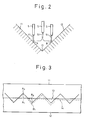
- Figure 2 is a diagram for explaining the weaving operation of the welding torch
- Fig. 3 is a diagram showing the relationship between the weld line of the base metals to be welded and weaving of the welding torch.
- the welding torch 5 weaves along a weld line 13.
- the weaving operation of the welding torch 13 is made by not only a horizontal zigzag movement but also by a vertical movement. According to this vertical movement, the welding torch 5 is raised high above the weld line 13.
- the waveform of the arc current detected by the arc sensor B is changed by a weaving operation to control the welding torch 5, and at the same time, arc welding of the members 11 and 12 is reliably performed.
- the welding wire 51 is sequentially and continuously supplied from a central portion of the welding torch 5, and an arc discharge is caused between the distal end of the welding wire 51 and the member 11 or 12.
- the welding wire 51 is melted by the heat accompanying the arc discharge, to thereby weld the members 11 and 12.
- Figures 4(a) and 4(b) are graphs of the arc current of Fig. 3, in which fig. 4(a) shows a waveform obtained when the welding torch 5 moves from one end A0 to the other end B0 of the weaving of Fig, 3 and Fig. 4(b) shows a waveform obtained when the welding torch 5 moves from one end A1 to the other end B1 of the weaving of Fig. 3.
- the waveform of the arc current becomes symmetrical. More specifically, the waveform of the arc current is minimum at a center time point t3 between a time point t1 corresponding to one end A0 of weaving and a time point t2 corresponding to the other end B0 of weaving, and areas S 1A and S 2A are equal to each other.
- the waveform of the arc current is not minimum at the center time point t3 between the time point t1 corresponding to one end A1 of weaving and the time point t2 corresponding to the other end B1 of weaving, and areas S 1a and S 2a are different from each other.
- the arc current changes as shown in Fig, 4(b) when the welding torch 5 deviates so that it is separated from the member 11 at one end A1 and close to the member 12 at the other end B1.
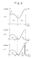
- Figures 5(a) to 5(c) are graphs for explaining the movement compensation processing of the welding torch when the arc current shown in Fig. 4(b) is detected
- Figure 6 is a flowchart of an example of the control operation according to the present invention.
- step 70 it is determined whether the end conditions are satisfied.
- the end conditions include, for example, the length of the welding line previously input. If YES in step 70, the processing of the correction of movement of the welding torch is ended.
- step 70 the flow advances to step 71 to move the welding torch 5 for the half period of weaving in accordance with a reference value, and the flow then goes to step 72 to detect the arc current. Note that, when the welding torch 5 is moved for the half period of weaving in accordance with the reference value, it is moved along the instructed weld line.
- the reference value is stored in the memory 9 or the like.
- step 72 When the arc current is detected by the arc sensor 8 in step 72, the minimum value of the detected arc current is set at 0 in step 73, as shown in Fig. 5(b). The arc current is then integrated on a time basis to calculate two areas S1 and S2 each corresponding to a 1/4 period, in step 74. In step 75, it is determined whether S1 > S2 (or S2 > S1). If S1 > S2 (or S2 > S1) is not satisfied in step 75, in other words, if it is determined that the two areas S1 and S2 coincide, the flow advances to step 71 through step 70, and the welding torch 5 is moved for the half period of weaving in accordance with the reference value.
- the wave form of the arc current is symmetrical, and the two areas S1 and S2 , each of which corresponds to a 1/4 period and which are the current integration values of the right and left weaving, become equal to each other.
- step 75 a correction area S 2c is calculated by subtracting, from the larger area S 2b , an area corresponding to a predetermined time period ⁇ at the end period of the larger area S 2b , and the correction area S 2c is compared with the smaller area S 1c .
- the correction area S 2c is an area obtained by integration starting from a center time point t 3c up to a time point t 2c , where the time point t 3c is the center time point of a time period which is a difference obtained by subtracting the predetermined time period ⁇ from a time period corresponding to the half period of the weaving, and the smaller area S 1c is an area obtained by integration starting from the time point t1 up to the center time point t 3c .
- the correction area S 2c is obtained by subtracting from the area S 2b , determined to be larger in step 75, the area corresponding to the predetermined time period ⁇ (S ⁇ ) at the end portion of the area S 2b , and is compared with the smaller area S 1c , for the following reasons. More specifically, with this procedure, a change in the arc current caused by a disturbance or the like is eliminated, and only-a change in the arc current caused by a change in positional relationship between the welding torch 5 and the members 11 and 12 to be welded can be identified.
- the predetermined time period ⁇ ( ⁇ 1 , ⁇ 2) is deemed to correspond to an end portion of the area S 2c (S1 , S2), for the following reasons. More specifically, a change in the arc current caused by a disturbance or the like generally occurs at an end of an area. With this procedure, only a change in the arc current caused by a change in the positional relationship between the welding torch 5 and the members 11 and 12 to be welded can be identified.
- step 76 if S1 - S ⁇ 1 > S2 (or S2 - S ⁇ 2 > S1) in step 76, the flow advances to step 77 to correct the reference value using the correction function, but if S1 - S ⁇ 1 > S2 (or S2 - S ⁇ 2 > S1 ) is not obtained in step 76, the flow advances to step 71 through step 70, and the welding torch 5 is moved for the half period of weaving in accordance with the reference value.
- step 78 determines whether the end condition are satisfied.
- the end conditions of step 78 are the same as the end conditions of step 70. If YES in step 78, the processing of the correction of movement of the welding torch 5 is ended, but if NO in step 78, the flow advances to step 79.
- step 79 the welding torch 5 is moved for the half period of weaving in accordance with the correction value, and the flow advances to step 72.
- the correction value is a value obtained by correcting the reference value using the correction function in step 77.
- the processing of the correction of movement of the welding torch is repeated every half period of weaving until YES is obtained in steps 70 and 78.
- step 77 The correction function of step 77 will be described.
- the correction function is used to correct movement of the welding torch when S1 - S ⁇ 1 > S2 (or S2 - S ⁇ 2 > S1) in step 76.
- the reference value in accordance with which the welding torch is moved along the instructed weld line, is corrected.
- the weaving operation of the next half period is corrected by the arc current caused by weaving of the preceding half period weaving.
- a correction function preferably has a curve that has a leading edge which becomes more moderate as the difference between the two areas each corresponding to a 1/4 period of the arc current (the difference between the current integration values of the right and left weaving) becomes larger.
- the welding torch can be corrected with a high sensitivity.
- a difference between the current integration values of the right and left weaving is large and a deviation of the welding torch is large, an abrupt correction is not made and thus the welding torch does not move in a zigzag manner.
- ⁇ C1 (
- This correction function can be mathematically processed comparatively easily and can be appropriately subjected to actual correction.
- the two areas used in this correction function are not limited to the correction areas S 2c and S 1c processed in the predetermined manner in step 76 but can be the areas S1 and s2 (S 1b and S 2b ) calculated in step 74.
Landscapes
- Engineering & Computer Science (AREA)
- Physics & Mathematics (AREA)
- Plasma & Fusion (AREA)
- Mechanical Engineering (AREA)
- Butt Welding And Welding Of Specific Article (AREA)
- Arc Welding In General (AREA)
- Arc Welding Control (AREA)
- Manipulator (AREA)
Abstract
Description
- The present invention relates to a control apparatus for an automatic arc welding machine, more particularly, to a control apparatus for an automatic arc welding machine for automatically performing arc welding by weaving a welding torch along a weld line, using an arc sensor to detect an arc current caused by the weaving, and compensating movement of the welding torch.
- In automatic arc welding a welding torch is made to weave along the weld line of base metals to be welded, and simultaneously, an arc current caused by the weaving is detected by an arc sensor to compensate movement of the welding torch, and thereby the weld line of the base metals is automatically arc welded. More specifically, when the actual weld line of the base metals to be welded deviates from an instructed weld line, the arc current is detected by the arc sensor and processed and thereby the movement of the welding torch is compensated to correctly move the welding torch along the actual weld line.
- In the processing of an arc current of a conventional control apparatus for an automatic arc welding machine, for example, the position, amplitude, and the like of an arc current detected by the arc sensor are monitored, and welding torch is moved for a predetermined distance in accordance with the peak value of the monitored position, amplitude, and the like, and as a result, the welding torch is moved along the actual weld line of the base metals.
- An arc current detected by an arc sensor has an unstable waveform because of disturbances occurring during arc welding and the like. In particular, although the peak value of the arc current is processed by smoothing the current waveform thereof through a filter or the like, a change in the arc current caused by a deviation of the welding torch from the weld line of the base metals cannot be easily discriminated from a change in the arc current caused by a disturbance or the like. Furthermore, a peak can occur in an arc current due to factors other than a deviation of the welding torch from the weld line, and as a result, an overcompensation of the movement of the welding torch occurs.
- JP-A-59-156577 discloses an arc welding system in which the weld position is controlled by calculating and comparing the integral of the detected welding current in successive 1/4 periods.
- JP-A-57-75288 discloses another arc welding system in which the arc current is detected and integrated in accordance with the oscillation periods.
- The object of the present invention is to correctly move the welding torch along the weld line of the base metals, and to perform arc welding even when an actual weld line of base metals to be welded deviates from an instructed weld line.
- According to the present invention, there is provided a control apparatus for an automatic arc welding machine for automatically performing arc welding by weaving a welding torch along a weld line, using an arc sensor to detect an arc current caused by the weaving, and compensating movement of said welding torch, the control apparatus comprising area calculating means for detecting the arc current at every half period of the welding, and integrating the arc current on a time basis to calculate two areas each corresponding to a 1/4 period; and, first area comparing discriminating means for comparing the two areas; characterised in that: the first area discriminating means discriminates between a first relatively large area and a second relatively small area; and by: second area comparing discriminating means for calculating a first correction area by subtracting a predetermined area from the first area, the predetermined area corresponding to a predetermined time period at an end portion of the first area, and comparing the first correction area with the second area; and, movement compensating means for correcting a reference value by using a correction function to compensate for the movement of said welding torch when the first correction area is larger than the second area.
- With the control apparatus for the automatic arc welding machine according to the present invention having the arrangement described above, the welding torch is caused to weave along the weld line to perform an automatic arc welding, an arc current caused by the weaving is detected by an arc sensor, and movement of the welding torch is compensated. The arc current detected at every half period of the weaving is integrated on a time basis by the area calculating means to calculate two areas each corresponding to a 1/4 period. The two areas are compared by the first area comparing discriminating means to discriminate between a first large area and a second small area. A first correction area is obtained by subtracting, from the first area, a predetermined area corresponding to a predetermined time period at the end portion of the first area. The first correction area is compared with the second area by the second area comparing discriminating means. When the first correction area is larger than the second area, the reference value is corrected by the movement compensating means by using the correction function, thereby compensating the movement of the welding torch. As a result, even when an actual weld line of base metals to be welded deviates from an instructed weld line, the welding torch is correctly moved along the weld line of the base metals and arc welding is performed.
- Preferably, when the difference between the first correction area and the second area becomes larger, the leading edge of the correction function is moderated so that an abrupt correction is not made.
- In the drawings:
- Fig. 1 is a schematic block diagram showing an embodiment of a control apparatus for an automatic arc welding machine according to the present invention;
- Fig. 2 is a diagram for explaining the weaving operation of the welding torch;
- Fig. 3 is a diagram showing the relationship between the weld line of the base metals to be welded and weaving of the welding torch;
- Figs. 4(a) and 4(b) are graphs of the arc current of Fig. 3;
- Figs. 5(a) to 5(c) are graphs for explaining the movement compensation processing of the welding torch when the arc current shown in Fig. 4(b) is detected; and
- Fig. 6 is a flowchart showing an example of the control operation based on the present invention.
- A control apparatus for an automatic arc welding machine according to an embodiment of the present invention will be described with reference to the accompanying drawings.
- Figure 1 is a schematic block diagram showing an embodiment of a control apparatus for an automatic arc welding machine according to the present invention.
- A
welding torch 5 is used to arc-weld base metals while supplying awelding wire 51, and when a voltage is applied to thewelding torch 5 by a welding power source (not shown), an arc is generated between the distal end of thewelding wire 51 and the base metals. The arc current flowing between the distal end of thewelding wire 51 and the base metals is measured by anarc sensor 8, data of the arc current is supplied to amicroprocessor 7, and thewelding torch 5 is controlled by a weldingtorch drive unit 6 operated by commands from themicroprocessor 7. As a result, thewelding torch 5 is caused to move and weave along the weld line of the base metals by the weldingtorch drive unit 6. Amemory 9 stores a correction function and the like, and upon reception of a command from themicroprocessor 7, thememory 9 supplies stored data, such as the correction function, to themicroprocessor 7. - Figure 2 is a diagram for explaining the weaving operation of the welding torch, and Fig. 3 is a diagram showing the relationship between the weld line of the base metals to be welded and weaving of the welding torch.
- As shown in Figs. 2 and 3, for example, when
members welding torch 5 weaves along aweld line 13. The weaving operation of thewelding torch 13 is made by not only a horizontal zigzag movement but also by a vertical movement. According to this vertical movement, thewelding torch 5 is raised high above theweld line 13. The waveform of the arc current detected by the arc sensor B is changed by a weaving operation to control thewelding torch 5, and at the same time, arc welding of themembers - The
welding wire 51 is sequentially and continuously supplied from a central portion of thewelding torch 5, and an arc discharge is caused between the distal end of thewelding wire 51 and themember welding wire 51 is melted by the heat accompanying the arc discharge, to thereby weld themembers - Figures 4(a) and 4(b) are graphs of the arc current of Fig. 3, in which fig. 4(a) shows a waveform obtained when the
welding torch 5 moves from one end A₀ to the other end B₀ of the weaving of Fig, 3 and Fig. 4(b) shows a waveform obtained when thewelding torch 5 moves from one end A₁ to the other end B₁ of the weaving of Fig. 3. - As shown in Fig, 4(a), when the actual weld line coincides with the instructed weld line and weaving of the
welding torch 5 is correctly performed, the waveform of the arc current becomes symmetrical. More specifically, the waveform of the arc current is minimum at a center time point t₃ between a time point t₁ corresponding to one end A₀ of weaving and a time point t₂ corresponding to the other end B₀ of weaving, and areas S1A and S2A are equal to each other. - As shown in Fig. 4(b), when the
actual weld line 14 is deviated from the instructedwelding line 13, the waveform of the arc current is not minimum at the center time point t₃ between the time point t₁ corresponding to one end A₁ of weaving and the time point t₂ corresponding to the other end B₁ of weaving, and areas S1a and S2a are different from each other. The arc current changes as shown in Fig, 4(b) when thewelding torch 5 deviates so that it is separated from themember 11 at one end A₁ and close to themember 12 at the other end B₁. - Figures 5(a) to 5(c) are graphs for explaining the movement compensation processing of the welding torch when the arc current shown in Fig. 4(b) is detected, Figure 6 is a flowchart of an example of the control operation according to the present invention.
- An example of the operation of the control apparatus for the automatic arc welding machine according to the present invention will be described with reference to Figs. 5 and 6.
- When the processing of the correction of movement of the welding torch is started, in
step 70 it is determined whether the end conditions are satisfied. The end conditions include, for example, the length of the welding line previously input. If YES instep 70, the processing of the correction of movement of the welding torch is ended. - In NO in
step 70, the flow advances tostep 71 to move thewelding torch 5 for the half period of weaving in accordance with a reference value, and the flow then goes tostep 72 to detect the arc current. Note that, when thewelding torch 5 is moved for the half period of weaving in accordance with the reference value, it is moved along the instructed weld line. The reference value is stored in thememory 9 or the like. - When the arc current is detected by the
arc sensor 8 instep 72, the minimum value of the detected arc current is set at 0 instep 73, as shown in Fig. 5(b). The arc current is then integrated on a time basis to calculate two areas S₁ and S₂ each corresponding to a 1/4 period, instep 74. Instep 75, it is determined whether S₁ > S₂ (or S₂ > S₁). If S₁ > S₂ (or S₂ > S₁) is not satisfied instep 75, in other words, if it is determined that the two areas S₁ and S₂ coincide, the flow advances tostep 71 throughstep 70, and thewelding torch 5 is moved for the half period of weaving in accordance with the reference value. In this case, when the actual weld line coincides with the instructed weld line and weaving of thewelding torch 5 is correctly performed, the wave form of the arc current is symmetrical, and the two areas S₁ and S₂ , each of which corresponds to a 1/4 period and which are the current integration values of the right and left weaving, become equal to each other. - If S₁ > S₂ (or S₂ > S₁) in
step 75, in other words, when it is determined that the area S2b is larger than an area S1b , as shown in Fig, 5(b), the flow advances tostep 76. Instep 76, a correction area S2c is calculated by subtracting, from the larger area S2b, an area corresponding to a predetermined time period α at the end period of the larger area S2b , and the correction area S2c is compared with the smaller area S1c. Note that, the correction area S2c is an area obtained by integration starting from a center time point t3c up to a time point t2c , where the time point t3c is the center time point of a time period which is a difference obtained by subtracting the predetermined time period α from a time period corresponding to the half period of the weaving, and the smaller area S1c is an area obtained by integration starting from the time point t₁ up to the center time point t3c. In this case, the correction area S2c is obtained by subtracting from the area S2b, determined to be larger instep 75, the area corresponding to the predetermined time period α (Sα) at the end portion of the area S2b , and is compared with the smaller area S1c , for the following reasons. More specifically, with this procedure, a change in the arc current caused by a disturbance or the like is eliminated, and only-a change in the arc current caused by a change in positional relationship between thewelding torch 5 and themembers welding torch 5 and themembers - In the above manner, if S₁ - Sα₁ > S₂ (or S₂ - Sα₂ > S₁) in
step 76, the flow advances to step 77 to correct the reference value using the correction function, but if S₁ - Sα₁ > S₂ (or S₂ - Sα₂ > S₁ ) is not obtained instep 76, the flow advances to step 71 throughstep 70, and thewelding torch 5 is moved for the half period of weaving in accordance with the reference value. - When the reference value is corrected using the correction function in
step 77, the flow advances tostep 78 to determine whether the end condition are satisfied. The end conditions ofstep 78 are the same as the end conditions ofstep 70. If YES instep 78, the processing of the correction of movement of thewelding torch 5 is ended, but if NO instep 78, the flow advances to step 79. - In
step 79, thewelding torch 5 is moved for the half period of weaving in accordance with the correction value, and the flow advances to step 72. Note that the correction value is a value obtained by correcting the reference value using the correction function instep 77. - As described above in detail, the processing of the correction of movement of the welding torch is repeated every half period of weaving until YES is obtained in
steps - The correction function of
step 77 will be described. - The correction function is used to correct movement of the welding torch when S₁ - Sα₁ > S₂ (or S₂ - Sα₂ > S₁) in
step 76. With the correction function, the reference value, in accordance with which the welding torch is moved along the instructed weld line, is corrected. When the reference value is corrected and movement of the welding torch is compensated, the weaving operation of the next half period is corrected by the arc current caused by weaving of the preceding half period weaving. - A correction function preferably has a curve that has a leading edge which becomes more moderate as the difference between the two areas each corresponding to a 1/4 period of the arc current (the difference between the current integration values of the right and left weaving) becomes larger. With such a correction function, when a difference between the current integration values of the right and left weaving is small and a deviation of the welding torch is small,
- the welding torch can be corrected with a high sensitivity. When when a difference between the current integration values of the right and left weaving is large and a deviation of the welding torch is large, an abrupt correction is not made and thus the welding torch does not move in a zigzag manner.
- Various types of correction functions that satisfy these conditions are available, and one that satisfies an equation:

- This correction function can be mathematically processed comparatively easily and can be appropriately subjected to actual correction. Note that the two areas used in this correction function are not limited to the correction areas S2c and S1c processed in the predetermined manner in
step 76 but can be the areas S₁ and s₂ (S1b and S2b) calculated instep 74.
Claims (5)
area calculating means (7) for detecting the arc current at every half period of the welding, and integrating the arc current on a time basis to calculate two areas (S₁,S₂) each corresponding to a 1/4 period; and,
first area comparing discriminating means (7) for comparing the two areas; characterised in that:
the first area discriminating means (7) discriminates between a first relatively large area (S₂) and a second relatively small area (S₁); and by:
second area comparing discriminating means (7) for calculating a first correction area by subtracting a predetermined area (Sα) from the first area, the predetermined area corresponding to a predetermined time period (a) at an end portion of the first area, and comparing the first correction area with the second area; and,
movement compensating means (7) for correcting a reference value by using a correction function to compensate for the movement of said welding torch (5) when the first correction area is larger than the second area.

ΔC₁ is a correction amount,
S1c is the first correction area,
S2c is the second area, and
Δ₁ is a correction constant.
Applications Claiming Priority (2)
| Application Number | Priority Date | Filing Date | Title |
|---|---|---|---|
| JP309258/86 | 1986-12-27 | ||
| JP61309258A JPH0630809B2 (en) | 1986-12-27 | 1986-12-27 | Control device of automatic arc welding machine |
Publications (3)
| Publication Number | Publication Date |
|---|---|
| EP0294485A1 EP0294485A1 (en) | 1988-12-14 |
| EP0294485A4 EP0294485A4 (en) | 1989-11-29 |
| EP0294485B1 true EP0294485B1 (en) | 1992-06-17 |
Family
ID=17990830
Family Applications (1)
| Application Number | Title | Priority Date | Filing Date |
|---|---|---|---|
| EP87907252A Expired EP0294485B1 (en) | 1986-12-27 | 1987-11-05 | Control apparatus for automatic arc welding machines |
Country Status (5)
| Country | Link |
|---|---|
| US (1) | US4857700A (en) |
| EP (1) | EP0294485B1 (en) |
| JP (1) | JPH0630809B2 (en) |
| DE (1) | DE3779908T2 (en) |
| WO (1) | WO1988004971A1 (en) |
Families Citing this family (5)
| Publication number | Priority date | Publication date | Assignee | Title |
|---|---|---|---|---|
| US5130514A (en) * | 1989-05-10 | 1992-07-14 | Daihen Corporation | Control apparatus for tracing a weld line in a welding apparatus and control method therefor |
| KR0124988B1 (en) * | 1994-09-28 | 1997-12-26 | 김준성 | Welding line path correction method of automatic welding machine |
| JP3746922B2 (en) * | 1999-08-17 | 2006-02-22 | 中央精機株式会社 | Welding line scanning determination device and scanning control device |
| US20130119032A1 (en) * | 2011-11-11 | 2013-05-16 | Lincoln Global, Inc. | System and method for welding materials of different conductivity |
| DE102012202355A1 (en) * | 2012-02-16 | 2013-08-22 | Bayerische Motoren Werke Aktiengesellschaft | Apparatus used for automatically operating controllable welding torch, comprises detection unit to determine parameters representing position of torch relative to welding point, and control unit to store control values and/or coordinates |
Family Cites Families (5)
| Publication number | Priority date | Publication date | Assignee | Title |
|---|---|---|---|---|
| JPS59156577A (en) * | 1983-02-23 | 1984-09-05 | Shin Meiwa Ind Co Ltd | Method and device for following up weld line |
| JPS6046870A (en) * | 1983-08-26 | 1985-03-13 | Hitachi Ltd | Welding line tracing control device |
| KR900003972B1 (en) * | 1985-04-30 | 1990-06-07 | 닛뽕 고오깡 가부시기가이샤 | Groove TRACING CONTROL OF HIGH SPEED ROTARY ARC FILLET WELDING |
| US4658112A (en) * | 1986-01-21 | 1987-04-14 | Crc-Evans Pipeline International, Inc. | Welding control by power integration |
| JPH06117590A (en) * | 1992-10-07 | 1994-04-26 | Nippon Steel Corp | Pipe fitting method |
-
1986
- 1986-12-27 JP JP61309258A patent/JPH0630809B2/en not_active Expired - Lifetime
-
1987
- 1987-11-05 WO PCT/JP1987/000854 patent/WO1988004971A1/en not_active Ceased
- 1987-11-05 EP EP87907252A patent/EP0294485B1/en not_active Expired
- 1987-11-05 DE DE8787907252T patent/DE3779908T2/en not_active Expired - Lifetime
- 1987-11-05 US US07/243,564 patent/US4857700A/en not_active Expired - Fee Related
Also Published As
| Publication number | Publication date |
|---|---|
| US4857700A (en) | 1989-08-15 |
| DE3779908T2 (en) | 1992-12-24 |
| JPS63168280A (en) | 1988-07-12 |
| EP0294485A4 (en) | 1989-11-29 |
| DE3779908D1 (en) | 1992-07-23 |
| WO1988004971A1 (en) | 1988-07-14 |
| EP0294485A1 (en) | 1988-12-14 |
| JPH0630809B2 (en) | 1994-04-27 |
Similar Documents
| Publication | Publication Date | Title |
|---|---|---|
| EP0902606B1 (en) | System and method for detecting nozzle and electrode wear | |
| US20080264916A1 (en) | Consumable Electrode Type Arc Welding Machine | |
| EP0607819B1 (en) | Pulsed arc welding apparatus having a consumable electrode wire | |
| EP1077101B1 (en) | Method and apparatus for determining seam tracking control of arc welding | |
| US20030038156A1 (en) | Method for continuously regulating or tracking a position of a welding torch or a welding head | |
| DE3274728D1 (en) | A method controlling an arc welding torch of a welding robot | |
| US5834732A (en) | Apparatus for controlling consumable electrode type pulsed arc welding power source | |
| EP2897755B1 (en) | Method, controller and welding system for controlling a welding operation based on a compensated stud voltage | |
| US5276308A (en) | Controller for resistance welding | |
| JPH0647172B2 (en) | Automatic welding equipment | |
| US4857700A (en) | Control apparatus for automatic arc welding machine | |
| EP0338078B1 (en) | Weaving welding with welding robot | |
| KR920006679B1 (en) | Automatic welding machine path correction method | |
| EP1013370A1 (en) | Method of detecting root gap and arc welding method using the former | |
| US4785155A (en) | Automatic welding machine path correction system | |
| US4634828A (en) | Control method of resistance welding | |
| US5306894A (en) | Consumable electrode type D.C. arc welder | |
| JPH064191B2 (en) | Output control method of power supply for consumable electrode type arc welding | |
| JP3303527B2 (en) | Method and apparatus for detecting welding wire position | |
| JP2591357B2 (en) | Distance calculation device and consumable electrode type arc welding power supply device using the same | |
| JP2545252B2 (en) | Spot welder cable damage detection method | |
| JP2533385B2 (en) | Burn-through detection method during welding | |
| JPH0631447A (en) | Method for controlling filler wire feed position of non-consumable electrode type arc welding | |
| JPH05245636A (en) | Consumable electrode arc welding method | |
| JP3208276B2 (en) | Groove width copying method |
Legal Events
| Date | Code | Title | Description |
|---|---|---|---|
| PUAI | Public reference made under article 153(3) epc to a published international application that has entered the european phase |
Free format text: ORIGINAL CODE: 0009012 |
|
| 17P | Request for examination filed |
Effective date: 19880915 |
|
| AK | Designated contracting states |
Kind code of ref document: A1 Designated state(s): DE FR GB |
|
| A4 | Supplementary search report drawn up and despatched |
Effective date: 19891129 |
|
| 17Q | First examination report despatched |
Effective date: 19910206 |
|
| GRAA | (expected) grant |
Free format text: ORIGINAL CODE: 0009210 |
|
| AK | Designated contracting states |
Kind code of ref document: B1 Designated state(s): DE FR GB |
|
| PG25 | Lapsed in a contracting state [announced via postgrant information from national office to epo] |
Ref country code: FR Effective date: 19920617 |
|
| REF | Corresponds to: |
Ref document number: 3779908 Country of ref document: DE Date of ref document: 19920723 |
|
| PGFP | Annual fee paid to national office [announced via postgrant information from national office to epo] |
Ref country code: GB Payment date: 19921026 Year of fee payment: 6 |
|
| EN | Fr: translation not filed | ||
| PLBE | No opposition filed within time limit |
Free format text: ORIGINAL CODE: 0009261 |
|
| STAA | Information on the status of an ep patent application or granted ep patent |
Free format text: STATUS: NO OPPOSITION FILED WITHIN TIME LIMIT |
|
| 26N | No opposition filed | ||
| PG25 | Lapsed in a contracting state [announced via postgrant information from national office to epo] |
Ref country code: GB Effective date: 19931105 |
|
| GBPC | Gb: european patent ceased through non-payment of renewal fee |
Effective date: 19931105 |
|
| PGFP | Annual fee paid to national office [announced via postgrant information from national office to epo] |
Ref country code: DE Payment date: 19991108 Year of fee payment: 13 |
|
| PG25 | Lapsed in a contracting state [announced via postgrant information from national office to epo] |
Ref country code: DE Free format text: LAPSE BECAUSE OF NON-PAYMENT OF DUE FEES Effective date: 20010801 |