EP0294396B1 - Pressurizable chemical shipping vessel - Google Patents
Pressurizable chemical shipping vessel Download PDFInfo
- Publication number
- EP0294396B1 EP0294396B1 EP87905511A EP87905511A EP0294396B1 EP 0294396 B1 EP0294396 B1 EP 0294396B1 EP 87905511 A EP87905511 A EP 87905511A EP 87905511 A EP87905511 A EP 87905511A EP 0294396 B1 EP0294396 B1 EP 0294396B1
- Authority
- EP
- European Patent Office
- Prior art keywords
- container
- vessel
- pressurizable
- pressurizable vessel
- inner container
- Prior art date
- Legal status (The legal status is an assumption and is not a legal conclusion. Google has not performed a legal analysis and makes no representation as to the accuracy of the status listed.)
- Expired
Links
- 239000000126 substance Substances 0.000 title claims abstract description 20
- 239000012530 fluid Substances 0.000 claims abstract description 51
- 238000010276 construction Methods 0.000 claims abstract description 18
- 239000000945 filler Substances 0.000 claims abstract description 12
- 239000011358 absorbing material Substances 0.000 claims description 8
- 229920005830 Polyurethane Foam Polymers 0.000 claims description 4
- 239000011152 fibreglass Substances 0.000 claims description 4
- 239000011496 polyurethane foam Substances 0.000 claims description 4
- 230000035939 shock Effects 0.000 claims description 4
- 230000005540 biological transmission Effects 0.000 claims description 2
- 229920001903 high density polyethylene Polymers 0.000 claims description 2
- 239000004700 high-density polyethylene Substances 0.000 claims description 2
- 229920006327 polystyrene foam Polymers 0.000 claims description 2
- 229920003002 synthetic resin Polymers 0.000 claims description 2
- 239000000057 synthetic resin Substances 0.000 claims description 2
- BFKJFAAPBSQJPD-UHFFFAOYSA-N tetrafluoroethene Chemical group FC(F)=C(F)F BFKJFAAPBSQJPD-UHFFFAOYSA-N 0.000 claims description 2
- 239000000463 material Substances 0.000 description 5
- 230000000712 assembly Effects 0.000 description 2
- 238000000429 assembly Methods 0.000 description 2
- 238000004140 cleaning Methods 0.000 description 2
- 239000002131 composite material Substances 0.000 description 2
- 238000000926 separation method Methods 0.000 description 2
- 230000002745 absorbent Effects 0.000 description 1
- 239000002250 absorbent Substances 0.000 description 1
- 239000003518 caustics Substances 0.000 description 1
- 230000007797 corrosion Effects 0.000 description 1
- 238000005260 corrosion Methods 0.000 description 1
- 239000007788 liquid Substances 0.000 description 1
- 238000012423 maintenance Methods 0.000 description 1
- 230000014759 maintenance of location Effects 0.000 description 1
- 238000000034 method Methods 0.000 description 1
- 239000000203 mixture Substances 0.000 description 1
- 230000000737 periodic effect Effects 0.000 description 1
- 239000004033 plastic Substances 0.000 description 1
- 229920003023 plastic Polymers 0.000 description 1
- 230000001681 protective effect Effects 0.000 description 1
- 239000002990 reinforced plastic Substances 0.000 description 1
- 229910001220 stainless steel Inorganic materials 0.000 description 1
- 239000010935 stainless steel Substances 0.000 description 1
- 229920002994 synthetic fiber Polymers 0.000 description 1
- 229910052902 vermiculite Inorganic materials 0.000 description 1
- 235000019354 vermiculite Nutrition 0.000 description 1
- 239000010455 vermiculite Substances 0.000 description 1
Images
Classifications
-
- B—PERFORMING OPERATIONS; TRANSPORTING
- B65—CONVEYING; PACKING; STORING; HANDLING THIN OR FILAMENTARY MATERIAL
- B65D—CONTAINERS FOR STORAGE OR TRANSPORT OF ARTICLES OR MATERIALS, e.g. BAGS, BARRELS, BOTTLES, BOXES, CANS, CARTONS, CRATES, DRUMS, JARS, TANKS, HOPPERS, FORWARDING CONTAINERS; ACCESSORIES, CLOSURES, OR FITTINGS THEREFOR; PACKAGING ELEMENTS; PACKAGES
- B65D85/00—Containers, packaging elements or packages, specially adapted for particular articles or materials
- B65D85/70—Containers, packaging elements or packages, specially adapted for particular articles or materials for materials not otherwise provided for
- B65D85/84—Containers, packaging elements or packages, specially adapted for particular articles or materials for materials not otherwise provided for for corrosive chemicals
-
- B—PERFORMING OPERATIONS; TRANSPORTING
- B65—CONVEYING; PACKING; STORING; HANDLING THIN OR FILAMENTARY MATERIAL
- B65D—CONTAINERS FOR STORAGE OR TRANSPORT OF ARTICLES OR MATERIALS, e.g. BAGS, BARRELS, BOTTLES, BOXES, CANS, CARTONS, CRATES, DRUMS, JARS, TANKS, HOPPERS, FORWARDING CONTAINERS; ACCESSORIES, CLOSURES, OR FITTINGS THEREFOR; PACKAGING ELEMENTS; PACKAGES
- B65D2213/00—Safety means
Definitions
- This invention relates to a pressurizable vessel for storing, transporting, and dispensing fluid chemicals having an inner container and an outer container the inner container having a filler neck extending from the upper surface thereof through a correspondingly sized neck opening in the upper surface of the outer container; the outer container being fitted around the inner container in spaced relationship therefrom; the space between the inner and outer containers being filled with an inert energy absorbing material to provide mechanical support for said inner container and to block the transmission of shock thereto.
- a vessel of this type has become known by US-A-3 501 055.
- a Starr, et al., US-A-3 724 712 describes a container for the bulk shipment of corrosive liquids.
- the container comprises a rigid outer shell with an inner flexible hollow container, able to conform to the walls of the outer shell by elastic and plastic deformation upon filling.
- the fluid chemical vessel of the present invention affords protection from shock and breakage by interposing an energy absorbing filler layer between the inner container and the outer shell.
- Boyd, US-A-4 305 518 shows a portable chemical resistant fibreglass reinforced plastic storgae tank, which is constructed with separable side walls and bottom section.
- the Boyd storage tank does not have the many advantageous novel features of the present shipping vessel, including easy separability of the outer shell and the inner fluid container and an energy absorbing filler layer therebetween to provide additional protection to the container and the fluid contents.
- a pressurizable vessel of the above identified type is characterized by the outer container consisting of an upper member and a base member separably attached to each other by cooperating securing means; the upper member contacting and supporting the inner container at the neck opening in the top surface of the upper member and at a concentric inward flange at the bottom of the side wall of the upper member (2); the base member being of double wall construction with the inner surface of the base member being shaped to contact and support the inner container by generally conforming to the bottom outer surface of the inner container; the space defined by the double wall construction of the base member of the outer container and the space defined between the inner container and the upper member of the outer container being filled with said inert energy absorbing material; and the base member and the upper member of the outer container and the inner container all being separable from each other upon detachment of the base member from the upper member.
- This invention provides an improved vessel for storing, transporting, and dispensing fluid chemicals and, more specifically, a shock and breakage resistant vessel for storing and transporting fluid chemicals, especially corrosive chemicals, and dispensing them under pressure to their point of use.
- a shock and breakage resistant vessel for storing and transporting fluid chemicals, especially corrosive chemicals, and dispensing them under pressure to their point of use.
- the present improved vessel is of a composite construction consisting of a two-part outer shell with a separable bottom, an inner chemically inert fluid container which can be removed when the outer shell is disassembled, and an energy absorbent material filling the space between the inner liner and the outer shell.
- the composite construction allows for easy replacement of individual parts which may become damaged in handling or shipping, thus providing for longer life and increased cost efficiency for the vessel.
- the inner fluid container is of seamless construction, designed to assure complete drainability in an inverted position. Since the present vessel is designed for repeated use as a returnable service container, ease of maintenance for periodic thorough cleaning is essential.
- the present novel vessel is of pressurizable design to facilitate transfer of the fluid chemical from the container through tubing to the point of use.
- pressures of 1406-2109 g/cm2 (20-30 psi) are generally employed.
- the present vessel is designed to withstand pressures of 3164 g/cm2 (45 psi).
- the improved vessel of this invention may be used with a detachable pressurizable fluid delivery insert assembly of any standard design and construction adapted for use with a pressurizable fluid container.
- the particular fluid delivery assembly insert forms no part of the present invention.
- the present novel chemical vessel is advantageously adapted for use with the bung drum insert assembly as described in the co-pending commonly owned application S.N. 815,025, now US-A- 4 699 298 issued Oct. 10, 1987 by Robert W. Grant, et al., entitled BUNG CONNECTION, which is a continuation-in-part of application S.N. 713,869, filed March 20, 1985 now abandoned, which description is specifically incorporated herein by reference.
- the vessels according to the present invention are designed to be easily and securely stackable, with the foot ring of one vessel nesting with the top stacking crown of another identical vessel.
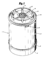
- Fig. 1. is a pictorial view of the complete vessel assembly secured with shipping/storage plug.
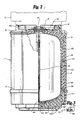
- Fig. 2. is a side elevational view of the complete vessel assembly with parts cut away and with an additional stacked vessel assembly shown in dashed line.
- Fig. 3 is a detail view of the fastener for securing the canister housing, shown slightly enlarged.
- the complete vessel assembly 1 comprises a generally rigid outer housing, consisting of an upper canister 2 and a separate canister base 4, with the canister base 4 removably secured to the upper canister 2 by means of a plurality of bolt fastener assemblies 30, shown in Figure 3.
- the canister base 4 overlaps the upper canister 2 by a slight lip, with the point of separation of the canister base 4 from the upper canister 2 demarcated by the separation line 6.
- the complete vessel assembly may desirably be of cylindrical shape to provide better resistance to the pressurization necessary during fluid delivery.
- the top surface of the upper canister 2 is provided with a plurality of upstanding flanges integral with the top surface, which upstanding flanges together form a circular stacking crown 8 concentric with and at a spaced distance from the outer perimeter rim 16 of the upper canister 2.
- the top surface of the upper canister 2 is further provided with an embossed area inside each of the plurality of flanges, so as to form with the flanges of the stacking crown 8, air passage reliefs 10 which are important for the stackability feature of the present novel vessel.
- the foot ring 46 of the canister base 4 will fit just inside the ring formed by the upstanding flanges of the circular stacking crown 8, as shown in Figure 2.
- the top surface of the upper canister 2 is formed with a gentle taper of, for example, about 3 degrees, away from the center bung nut 12.
- the area on the top surface of the upper canister 2 defined between the outer perimeter rim 16 and the circular stacking crown 8 forms a recessed concentric well to confine any minor amount of spillage from the bung connection preventing drippage down the sides of the vessel assembly 1.
- a plurality of indented hand holds 18 may desirably be provided on the wall of the upper canister 2 underneath the rim 16.
- the outer housing is desirably formed of a high impact and corrosion resistant synthetic material such as, for example, a high density polyethylene.
- the center of the top surface of the upper canister 2 is designed to accommodate the bottle nut 12 of the bung adaptor sleeve of a detachable fluid delivery insert assembly for delivering under suitable pressure the fluid contents of the vessel to the desired point of use.
- the fluid delivery insert assembly 1 may be of any standard design and construction adapted for use with a pressurizable fluid container. in Figure 1, the complete vessel assembly 1 is shown with the shipping/storage plug 14 of the fluid delivery insert assembly in place.
- the complete vessel assembly 1 may be of any desirable size, with a vessel having a capacity of 100 liters of fluid being advantageous for general commercial use.
- the vessel assembly 1 is shown with parts cut away to illustrate the separable outer housing, the inner fluid container 20, the energy absorbing filler material 22 and other details of construction.
- the necked inner fluid container 20 is disposed in spaced relationship to the inner surfaces of the generally rigid outer housing, with a slight concave well 42 on the middle of the bottom of the inner surface of the fluid container 20 to accommodate the tubular ducting 24 of the fluid delivery insert assembly.
- An advantageous feature of the bottom concave well 42 allows for a maximum of 99.5% by volume of the fluid chemical contents to be delivered from the present novel vessel under normal pressurized delivery. With pressurized fluid delivery from conventional vessels not possessing this advantageous bottom well construction, it is usual for 4-5% by volume of residual fluid contents to remain in the bottom as wastage.
- the outer housing of the vessel assembly 1 consists of the upper canister 2 and the canister base 4 secured thereto by means of a plurality of fastener assemblies 30.
- Each fastener assembly 30 comprises a stainless steel bolt which fits snugly through an aperture in the canister base 4 and a corresponding aperture in the concentric inward directed flange 48 at the bottom of the side wall of the upper canister 2 and is secured in place with a blind nut 36 on the interior of the flange 48 and a hex head cap 38 on the bottom surface of the canister base 4.
- the necked inner fluid container 20 may desirably be formed of a liner 26 with an exterior layup 28, so that the entire vessel assembly 1 may withstand pressures for fluid delivery of up to about 3164 g/cm2 (45 psi).
- the liner 26 may be of tetrafluoroethylene synthetic resin and the layup 28 may be of fiberglass.
- the space between the inner fluid container 20 and the upper canister 2 is filled with an energy absorbing material 22 such as, for example, vermiculite, fiberglass batting, polystyrene foam, polyurethane foam, and the like.
- the filler material be performed to conform to the area defined betwen the inner fluid container 20 and the upper canister 2 in order to avoid any settling or shifting of the filler contents during handling and shipping.
- the filler material may be formed of polyurethane foam.
- the inner fluid container 20 is formed of seamless construction throughout to provide easy and complete drainability in an inverted position, and to prevent undesirable retention of any of the fluid contents during cleaning procedures.
- the canister base 4 is formed of a double wall construction, with the inner surface of the canister base 4 generally conforming to the shape of the bottom of the inner fluid container 20 as a support diaphragm 40. The middle of the inner surface of the canister base 4 has a liner socket cup 44 to accommodate the well 42 on the bottom of the inner fluid container 20.
- the interior of the double wall construction of the canister base 4 is filled with filler material of the same composition and preformed construction as that used for the filler 22 in the space between the inner fluid container 20 and the upper canister 2.
- the inner fluid container 20 is supported by contact with the concentric inward directed flange 48 at the bottom of the side wall of the upper canister 2 and by contact with the neck opening in the middle of the top surface of the upper canister 2.
- the bottom of the canister base 4 terminates in a protruding concentric foot ring 46, which is sized and positioned to nest just inside the circular stacking crown 8 on the top surface of the upper canister 2, as shown in Figure 2.
- the neck of the inner fluid container 20 has threads 32 formed on the upper outer surface thereof.
- a bottle nut 12 with interior threading is designed to engage the threads 32 on the upper outer surface of the inner fluid container 20 and is also attached to the tubular ducting 24 of the fluid delivery insert assembly.
- the fluid delivery insert assembly may be of any standard design and construction adapted for use with a pressurizable fluid container and the fluid delivery insert assembly itself forms no portion of the present invention. As shown in Figures 1 and 2, when secured for storage or transport, the complete vessel assembly of this invention is provided with a shipping/storage plug 14, which is screw fit with the bottle nut 12.
Landscapes
- Health & Medical Sciences (AREA)
- Chemical & Material Sciences (AREA)
- Chemical Kinetics & Catalysis (AREA)
- General Chemical & Material Sciences (AREA)
- General Health & Medical Sciences (AREA)
- Toxicology (AREA)
- Engineering & Computer Science (AREA)
- Mechanical Engineering (AREA)
- Filling Or Discharging Of Gas Storage Vessels (AREA)
- Containers And Packaging Bodies Having A Special Means To Remove Contents (AREA)
Abstract
Description
- This invention relates to a pressurizable vessel for storing, transporting, and dispensing fluid chemicals having an inner container and an outer container the inner container having a filler neck extending from the upper surface thereof through a correspondingly sized neck opening in the upper surface of the outer container; the outer container being fitted around the inner container in spaced relationship therefrom; the space between the inner and outer containers being filled with an inert energy absorbing material to provide mechanical support for said inner container and to block the transmission of shock thereto.
- A vessel of this type has become known by US-A-3 501 055.
- There are currently available a large variety of containers for fluid chemicals, none of which offer the convenience, safety, and combination of features provided by the present novel chemical vessel.
- R. Jurion, et al., US-A-3 501 055 describes a container for storing and dispensing caustic substances, which utilizes an energy absorbing material to protect and support the inner vessel inside the outer container shell. The container described by Jurion, however, does not possess the specific novel features of the present vessel, which include an outer protective shell with an easily separable bottom to facilitate access to the inner fluid container and interchange of parts which may have been damaged in handling and shipping.
- A Starr, et al., US-A-3 724 712 describes a container for the bulk shipment of corrosive liquids. The container comprises a rigid outer shell with an inner flexible hollow container, able to conform to the walls of the outer shell by elastic and plastic deformation upon filling. The fluid chemical vessel of the present invention, among other features not found in the Starr container, affords protection from shock and breakage by interposing an energy absorbing filler layer between the inner container and the outer shell.
- Boyd, US-A-4 305 518 shows a portable chemical resistant fibreglass reinforced plastic storgae tank, which is constructed with separable side walls and bottom section. Again, the Boyd storage tank does not have the many advantageous novel features of the present shipping vessel, including easy separability of the outer shell and the inner fluid container and an energy absorbing filler layer therebetween to provide additional protection to the container and the fluid contents.
- According to the present invention a pressurizable vessel of the above identified type is characterized by the outer container consisting of an upper member and a base member separably attached to each other by cooperating securing means; the upper member contacting and supporting the inner container at the neck opening in the top surface of the upper member and at a concentric inward flange at the bottom of the side wall of the upper member (2); the base member being of double wall construction with the inner surface of the base member being shaped to contact and support the inner container by generally conforming to the bottom outer surface of the inner container; the space defined by the double wall construction of the base member of the outer container and the space defined between the inner container and the upper member of the outer container being filled with said inert energy absorbing material; and the base member and the upper member of the outer container and the inner container all being separable from each other upon detachment of the base member from the upper member.
- This invention provides an improved vessel for storing, transporting, and dispensing fluid chemicals and, more specifically, a shock and breakage resistant vessel for storing and transporting fluid chemicals, especially corrosive chemicals, and dispensing them under pressure to their point of use. Other unique aspects of the chemical vessel of the present invention are described by the following features.
- The present improved vessel is of a composite construction consisting of a two-part outer shell with a separable bottom, an inner chemically inert fluid container which can be removed when the outer shell is disassembled, and an energy absorbent material filling the space between the inner liner and the outer shell. The composite construction allows for easy replacement of individual parts which may become damaged in handling or shipping, thus providing for longer life and increased cost efficiency for the vessel.
- The inner fluid container is of seamless construction, designed to assure complete drainability in an inverted position. Since the present vessel is designed for repeated use as a returnable service container, ease of maintenance for periodic thorough cleaning is essential.
- The present novel vessel is of pressurizable design to facilitate transfer of the fluid chemical from the container through tubing to the point of use. In most normal pressurized dispensing procedures from a pressurizable container, pressures of 1406-2109 g/cm² (20-30 psi) are generally employed. The present vessel is designed to withstand pressures of 3164 g/cm² (45 psi). In dispensing the fluid chemical contents to their point of use, the improved vessel of this invention may be used with a detachable pressurizable fluid delivery insert assembly of any standard design and construction adapted for use with a pressurizable fluid container. The particular fluid delivery assembly insert forms no part of the present invention. However, the present novel chemical vessel is advantageously adapted for use with the bung drum insert assembly as described in the co-pending commonly owned application S.N. 815,025, now US-A- 4 699 298 issued Oct. 10, 1987 by Robert W. Grant, et al., entitled BUNG CONNECTION, which is a continuation-in-part of application S.N. 713,869, filed March 20, 1985 now abandoned, which description is specifically incorporated herein by reference.
- Further, in order to facilitate efficient handling, transport and storage, the vessels according to the present invention are designed to be easily and securely stackable, with the foot ring of one vessel nesting with the top stacking crown of another identical vessel.
- These and other features of the novel fluid chemical vessel of this invention will be apparent to those skilled in this art upon reading the following detailed description in reference to the accompanying drawings.
- Fig. 1. is a pictorial view of the complete vessel assembly secured with shipping/storage plug.
- Fig. 2. is a side elevational view of the complete vessel assembly with parts cut away and with an additional stacked vessel assembly shown in dashed line.
- Fig. 3 is a detail view of the fastener for securing the canister housing, shown slightly enlarged.
- In Figure 1, the complete vessel assembly 1 according to this invention comprises a generally rigid outer housing, consisting of an
upper canister 2 and aseparate canister base 4, with thecanister base 4 removably secured to theupper canister 2 by means of a plurality ofbolt fastener assemblies 30, shown in Figure 3. Thecanister base 4 overlaps theupper canister 2 by a slight lip, with the point of separation of thecanister base 4 from theupper canister 2 demarcated by theseparation line 6. The complete vessel assembly may desirably be of cylindrical shape to provide better resistance to the pressurization necessary during fluid delivery. - The top surface of the
upper canister 2 is provided with a plurality of upstanding flanges integral with the top surface, which upstanding flanges together form acircular stacking crown 8 concentric with and at a spaced distance from theouter perimeter rim 16 of theupper canister 2. The top surface of theupper canister 2 is further provided with an embossed area inside each of the plurality of flanges, so as to form with the flanges of thestacking crown 8,air passage reliefs 10 which are important for the stackability feature of the present novel vessel. In stacking, thefoot ring 46 of thecanister base 4 will fit just inside the ring formed by the upstanding flanges of thecircular stacking crown 8, as shown in Figure 2. The top surface of theupper canister 2 is formed with a gentle taper of, for example, about 3 degrees, away from thecenter bung nut 12. Thus, the area on the top surface of theupper canister 2 defined between theouter perimeter rim 16 and thecircular stacking crown 8 forms a recessed concentric well to confine any minor amount of spillage from the bung connection preventing drippage down the sides of the vessel assembly 1. A plurality of indented hand holds 18 may desirably be provided on the wall of theupper canister 2 underneath therim 16. The outer housing is desirably formed of a high impact and corrosion resistant synthetic material such as, for example, a high density polyethylene. - The center of the top surface of the
upper canister 2 is designed to accommodate thebottle nut 12 of the bung adaptor sleeve of a detachable fluid delivery insert assembly for delivering under suitable pressure the fluid contents of the vessel to the desired point of use. The fluid delivery insert assembly 1 may be of any standard design and construction adapted for use with a pressurizable fluid container. in Figure 1, the complete vessel assembly 1 is shown with the shipping/storage plug 14 of the fluid delivery insert assembly in place. The complete vessel assembly 1 may be of any desirable size, with a vessel having a capacity of 100 liters of fluid being advantageous for general commercial use. - In Figure 2, the vessel assembly 1 is shown with parts cut away to illustrate the separable outer housing, the
inner fluid container 20, the energy absorbingfiller material 22 and other details of construction. The neckedinner fluid container 20 is disposed in spaced relationship to the inner surfaces of the generally rigid outer housing, with a slightconcave well 42 on the middle of the bottom of the inner surface of thefluid container 20 to accommodate thetubular ducting 24 of the fluid delivery insert assembly. An advantageous feature of the bottomconcave well 42 allows for a maximum of 99.5% by volume of the fluid chemical contents to be delivered from the present novel vessel under normal pressurized delivery. With pressurized fluid delivery from conventional vessels not possessing this advantageous bottom well construction, it is usual for 4-5% by volume of residual fluid contents to remain in the bottom as wastage. - The outer housing of the vessel assembly 1 consists of the
upper canister 2 and thecanister base 4 secured thereto by means of a plurality offastener assemblies 30. Eachfastener assembly 30 comprises a stainless steel bolt which fits snugly through an aperture in thecanister base 4 and a corresponding aperture in the concentric inward directedflange 48 at the bottom of the side wall of theupper canister 2 and is secured in place with ablind nut 36 on the interior of theflange 48 and ahex head cap 38 on the bottom surface of thecanister base 4. The neckedinner fluid container 20 may desirably be formed of aliner 26 with anexterior layup 28, so that the entire vessel assembly 1 may withstand pressures for fluid delivery of up to about 3164 g/cm² (45 psi). Thus, desirably, theliner 26 may be of tetrafluoroethylene synthetic resin and thelayup 28 may be of fiberglass. The space between theinner fluid container 20 and theupper canister 2 is filled with anenergy absorbing material 22 such as, for example, vermiculite, fiberglass batting, polystyrene foam, polyurethane foam, and the like. It is preferred that the filler material be performed to conform to the area defined betwen theinner fluid container 20 and theupper canister 2 in order to avoid any settling or shifting of the filler contents during handling and shipping. Desirably, the filler material may be formed of polyurethane foam. Theinner fluid container 20 is formed of seamless construction throughout to provide easy and complete drainability in an inverted position, and to prevent undesirable retention of any of the fluid contents during cleaning procedures. Thecanister base 4 is formed of a double wall construction, with the inner surface of thecanister base 4 generally conforming to the shape of the bottom of theinner fluid container 20 as asupport diaphragm 40. The middle of the inner surface of thecanister base 4 has aliner socket cup 44 to accommodate the well 42 on the bottom of theinner fluid container 20. The interior of the double wall construction of thecanister base 4 is filled with filler material of the same composition and preformed construction as that used for thefiller 22 in the space between theinner fluid container 20 and theupper canister 2. In addition to the support provided by thesupport diaphragm 40, theinner fluid container 20 is supported by contact with the concentric inward directedflange 48 at the bottom of the side wall of theupper canister 2 and by contact with the neck opening in the middle of the top surface of theupper canister 2. The bottom of thecanister base 4 terminates in a protrudingconcentric foot ring 46, which is sized and positioned to nest just inside the circular stackingcrown 8 on the top surface of theupper canister 2, as shown in Figure 2. - The neck of the
inner fluid container 20 hasthreads 32 formed on the upper outer surface thereof. Abottle nut 12 with interior threading is designed to engage thethreads 32 on the upper outer surface of theinner fluid container 20 and is also attached to thetubular ducting 24 of the fluid delivery insert assembly. The fluid delivery insert assembly, as has been previously mentioned, may be of any standard design and construction adapted for use with a pressurizable fluid container and the fluid delivery insert assembly itself forms no portion of the present invention. As shown in Figures 1 and 2, when secured for storage or transport, the complete vessel assembly of this invention is provided with a shipping/storage plug 14, which is screw fit with thebottle nut 12.
Claims (10)
- A pressurizable vessel (1) for storing, transporting, and dispensing fluid chemicals having an inner container (20) and an outer container (2, 4),
the inner container (20) having a filler neck extending from the upper surface thereof through a correspondingly sized neck opening in the upper surface of the outer container;
the outer container being fitted around the inner container in spaced relationship therefrom;
the space between the inner and outer containers being filled with an inert energy absorbing material (22) to provide mechanical support for said inner container (20) and to block the transmission of shock thereto;
characterized by:
the outer container consisting of an upper member (2) and a base member (4) separably attached to each other by cooperating securing means (36, 38);
the upper member (2) contacting and supporting the inner container (20) at the neck opening in the top surface of the upper member (2) and at a concentric inward flange (48) at the bottom of the side wall of the upper member (2);
the base member (4) being of double wall construction with the inner surface of the base member (4) being shaped to contact and support the inner container (20) by generally conforming to the bottom outer surface of the inner container (20);
the space defined by the double wall construction of the base member (4) of the outer container and the space defined between the inner container (20) and the upper member (2) of the outer container being filled with said inert energy absorbing material (22); and
the base member (4) and the upper member (2) of the outer container and the inner container (20) all being separable from each other upon detachment of the base member (4) from the upper member (2). - A pressurizable vessel (1) according to claim 1, wherein the inner container (20) is of seamless construction with a slight concave well (42) on the middle of the bottom of the inner surface and is comprised of an inner liner (26) with an exterior layup (28).
- A pressurizable vessel (1) according to claim 2, wherein the inner container (20) is comprised of an inner liner (26) of tetrafluoroethylene synthetic resin with an exterior layup (28) of fibreglass.
- A pressurizable vessel (1) according to claim 2, wherein the outer container is of high density polyethylene.
- A pressurizable vessel (1) according to claim 1, wherein:
the top surface of the upper member (2) of the outer container is provided with a plurality of upstanding flanges integral with the top surface, which upstanding flanges together form a circular stacking crown (8) concentric with and at a spaced distance from the outer perimeter rim (16) of the top surface such that a recessed concentric area on the top surface is defined between the stacking crown and the outer perimeter rim (16); and
the bottom of the base member (4) of the outer container terminates in a protruding concentric foot ring (46) which is sized and positioned such that the foot ring (46) of the base member (4) of a first pressurizable vessel (1) nests in stacking arrangement just inside the circular stacking crown (8) on the top surface of the upper member (2) of a second pressurizable vessel (1). - A pressurizable vessel (1) according to claim 5, wherein a plurality of intended hand holds (18) are provided on the wall of the upper member (2) of the outer container underneath the perimeter rim (16) thereof.
- A pressurizable vessel (1) according to claim 1, wherein the inert energy absorbing material (22) is polystyrene foam, and polyurethane foam.
- A pressurizable vessel (1) according to claim 7, wherein the inert energy absorbing material (2) is performed of polyurethane foam.
- A pressurizable vessel (1) according to claim 1, wherein the filler neck of the inner container is adapted to accept a detachable pressurizable fluid delivery insert assembly (24).
- A pressurizable vessel (1) according to claim 1, with a capacity of 100 liters and able to withstand pressures of 3164 g/cm² (45 psi).
Applications Claiming Priority (2)
| Application Number | Priority Date | Filing Date | Title |
|---|---|---|---|
| US06/934,483 US4793491A (en) | 1986-11-24 | 1986-11-24 | Pressurizable chemical shipping vessel |
| US934483 | 1986-11-24 |
Publications (3)
| Publication Number | Publication Date |
|---|---|
| EP0294396A1 EP0294396A1 (en) | 1988-12-14 |
| EP0294396A4 EP0294396A4 (en) | 1989-03-29 |
| EP0294396B1 true EP0294396B1 (en) | 1992-09-30 |
Family
ID=25465634
Family Applications (1)
| Application Number | Title | Priority Date | Filing Date |
|---|---|---|---|
| EP87905511A Expired EP0294396B1 (en) | 1986-11-24 | 1987-08-03 | Pressurizable chemical shipping vessel |
Country Status (4)
| Country | Link |
|---|---|
| US (1) | US4793491A (en) |
| EP (1) | EP0294396B1 (en) |
| DE (1) | DE3782054T2 (en) |
| WO (1) | WO1988003899A1 (en) |
Families Citing this family (54)
| Publication number | Priority date | Publication date | Assignee | Title |
|---|---|---|---|---|
| FR2628074B1 (en) | 1988-03-01 | 1990-06-22 | Plastic Omnium Cie | FUT FOR THE TRANSPORT AND STORAGE OF CHEMICALS |
| US4930648A (en) * | 1989-06-08 | 1990-06-05 | Essex Environmental Industries, Inc. | Triple seal molded outlet for plastic storage container |
| US4899899A (en) * | 1989-06-21 | 1990-02-13 | Triten Corporation | Pressure vessel |
| US4964529A (en) * | 1989-06-30 | 1990-10-23 | Houston Robert S | Gas tank container |
| US4927040A (en) * | 1989-08-07 | 1990-05-22 | Owens-Illinois Plastic Products Inc. | Plastic drum and method of making |
| DE9015191U1 (en) * | 1990-11-05 | 1991-01-17 | Riedel-de Haen AG, 30926 Seelze | Chemical transport containers |
| US5154295A (en) * | 1990-11-13 | 1992-10-13 | Stoner Theodore A | Interlocking container structures |
| US6047846A (en) | 1991-02-25 | 2000-04-11 | Greif Bros. Corp. Of Ohio | Plastic drum with drain sump |
| US5312013A (en) * | 1991-05-22 | 1994-05-17 | Aladdin Industries, Incorporated | Beverage container construction |
| US5465891A (en) * | 1991-05-22 | 1995-11-14 | Aladdin Industries, Inc. | Beverage container holder |
| DK140291D0 (en) * | 1991-07-26 | 1991-07-26 | Klinge Cylindric A S | TRANSPORTABLE CONTAINER FOR DISPOSED GASES UNDER PRESSURE |
| US5267669A (en) * | 1991-09-09 | 1993-12-07 | Dixon Robert M | Self serve beverage dispenser |
| US5337917A (en) * | 1991-10-21 | 1994-08-16 | Sandia Corporation | Crash resistant container |
| US5259509A (en) * | 1992-03-09 | 1993-11-09 | Boal Jr Stewart | Stackable storage tank |
| US5398842A (en) * | 1992-05-27 | 1995-03-21 | Whirley Industries, Inc. | Thermal container |
| US5290046A (en) * | 1992-07-08 | 1994-03-01 | Houston James L | Internal live loading packing gland |
| US5454477A (en) * | 1992-09-04 | 1995-10-03 | Vari-Lite, Inc. | Storage and transporatation trunk for lighting equipment |
| FR2706427B1 (en) * | 1993-06-11 | 1995-08-11 | Merck Patent Gmbh | Container for transport, storage and distribution of chemicals. |
| US5430927A (en) * | 1993-07-06 | 1995-07-11 | Snyder Industries, Inc. | Double walled tank and method of making the same |
| US5782381A (en) * | 1993-12-09 | 1998-07-21 | American Cyanamid Company | Container for carrying and dispensing liquid and semi-liquid products |
| AU749309B2 (en) * | 1994-05-11 | 2002-06-20 | Odin | Internally pressurised fluid container |
| FR2719825B1 (en) * | 1994-05-11 | 1996-10-11 | Odin | Fluid container with internal pressure. |
| US5597085A (en) * | 1994-07-20 | 1997-01-28 | Fluoroware, Inc. | Composite, pressure-resistant drum type container |
| USD385943S (en) * | 1995-05-12 | 1997-11-04 | Monsanto Company | Fluid container |
| US5651523A (en) * | 1995-08-31 | 1997-07-29 | Aladdin Industries, Inc. | Article support system having multiple utilities |
| US5584411A (en) * | 1995-11-21 | 1996-12-17 | Chemical Engineering Corporation | Tank assembly and method for water treatment |
| US5890750A (en) * | 1996-08-23 | 1999-04-06 | Chemical Engineering Corporation | Tank assembly and method for water treatment |
| US6089399A (en) * | 1997-01-14 | 2000-07-18 | Chatwins Group, Inc. | Inert-metal lined, seamless steel-body cylinder |
| US5928743A (en) * | 1997-07-24 | 1999-07-27 | Purepak Technology Corporation | Pressurized gas vessel having internal chemical surface |
| US5960708A (en) * | 1998-06-16 | 1999-10-05 | Detemple; Donald Edward | Atmospheric controlled shipping container |
| FR2792392B1 (en) * | 1999-04-19 | 2001-06-29 | Claude Leon Hembert | DEVICE FOR PROTECTING A CONTAINER AND CONTAINER PROVIDED WITH SUCH A DEVICE |
| DE10007502A1 (en) * | 2000-02-18 | 2001-08-23 | Basell Polypropylen Gmbh | Inner container for household appliances |
| GB0022710D0 (en) * | 2000-09-15 | 2000-11-01 | Bp Oil Int | Dispenser and method of use |
| MXPA04003407A (en) * | 2001-10-12 | 2005-04-11 | Polymer & Steel Technologies H | Composite pressure vessel assembly and method. |
| US20040033163A1 (en) * | 2001-11-26 | 2004-02-19 | Lab Vision Corporation | Automated tissue staining system and reagent container |
| US6998270B2 (en) * | 2001-11-26 | 2006-02-14 | Lab Vision Corporation | Automated tissue staining system and reagent container |
| US20040031705A1 (en) * | 2002-06-17 | 2004-02-19 | Detemple Thomas E. | Atmospheric controlled container |
| US7258250B2 (en) * | 2002-08-21 | 2007-08-21 | L'oreal | Receptacle having a reinforced wall |
| AT7582U1 (en) * | 2003-02-18 | 2005-05-25 | Magna Steyr Fahrzeugtechnik Ag | DOUBLE-WALLED CONTAINER FOR CRYOGENEOUS LIQUIDS |
| US7028553B2 (en) * | 2003-05-16 | 2006-04-18 | Pacific Consolidated Industries, Llc | Apparatus for delivering pressurized fluid |
| US20060108371A1 (en) * | 2004-04-18 | 2006-05-25 | Rauworth Barry L | Blow-molded drum |
| KR200375496Y1 (en) * | 2004-11-02 | 2005-03-11 | 권영호 | A Safety Cover of Portable Gas Container |
| US20070037346A1 (en) * | 2005-02-22 | 2007-02-15 | Grant Robert W | Rapid thermal annealing of targeted thin film layers |
| US7731051B2 (en) * | 2005-07-13 | 2010-06-08 | Gm Global Technology Operations, Inc. | Hydrogen pressure tank including an inner liner with an outer annular flange |
| US7754138B1 (en) | 2006-07-10 | 2010-07-13 | Akira Kashiwase | Apparatus and method of manufacturing stackable containers |
| JP5416117B2 (en) * | 2007-08-28 | 2014-02-12 | インテグリス・インコーポレーテッド | Fluid distribution method and apparatus |
| NL2003133C2 (en) * | 2009-07-03 | 2011-01-04 | Heineken Supply Chain Bv | Tapping apparatus and compressible bottle therefore, and a preform for forming such container. |
| ITPN20130028A1 (en) * | 2013-05-23 | 2014-11-24 | Gianfranco Bisaro | IMPROVED PACKAGING FOR BARRELS, IN PARTICULAR KEG |
| US10196172B2 (en) * | 2014-03-13 | 2019-02-05 | Wuxi Huaying Microelectronics Technology Co., Ltd. | Chemical container and method for manufacturing the same |
| US10943802B2 (en) * | 2018-07-31 | 2021-03-09 | Taiwan Semiconductor Manufacturing Co., Ltd. | Photoresist bottle container |
| US10543978B1 (en) | 2018-08-17 | 2020-01-28 | Sigma Phase, Corp. | Rapidly cooling food and drinks |
| US11470855B2 (en) * | 2018-08-17 | 2022-10-18 | Coldsnap, Corp. | Providing single servings of cooled foods and drinks |
| US11490749B2 (en) * | 2019-10-24 | 2022-11-08 | Lenox Corporation | Nested tableware set |
| DE102022119050A1 (en) * | 2022-07-29 | 2024-02-01 | AS Strömungstechnik Gesellschaft mit beschränkter Haftung | Extraction system |
Family Cites Families (15)
| Publication number | Priority date | Publication date | Assignee | Title |
|---|---|---|---|---|
| US2103677A (en) * | 1934-10-09 | 1937-12-28 | Ethel H Morrison | Spaced wall receptacle |
| US2131792A (en) * | 1934-10-15 | 1938-10-04 | Pressed Steel Tank Company | Metal container |
| US2426630A (en) * | 1943-09-27 | 1947-09-02 | Specialties Dev Corp | High-pressure gaseous oxygen package |
| US2503339A (en) * | 1946-10-18 | 1950-04-11 | Houdaille Hershey Corp | Metallic beer barrel |
| US3093264A (en) * | 1955-04-04 | 1963-06-11 | Minnesota Mining & Mfg | Metallic article lined with a halogenated olefin polymer film |
| GB799285A (en) * | 1955-08-23 | 1958-08-06 | Neville Gwilliam Lloyd | Improvements in or relating to metal containers for liquids |
| FR1237018A (en) * | 1958-10-06 | 1960-11-23 | Union Carbide Corp | Double-walled container for liquefied gases |
| US3098578A (en) * | 1960-01-15 | 1963-07-23 | Bruner Corp | Pressure vessel |
| US3044607A (en) * | 1960-05-23 | 1962-07-17 | United Aircraft Corp | Shipping container |
| US3210228A (en) * | 1961-07-06 | 1965-10-05 | Trw Inc | Method and apparatus for making a filament wound pressure vessel |
| NL278554A (en) * | 1962-05-18 | |||
| US3508677A (en) * | 1968-08-20 | 1970-04-28 | Whittaker Corp | Vessel for storing high-pressure gases |
| US4000826A (en) * | 1975-10-17 | 1977-01-04 | Rogers Thelmer A | Cryogenic transport |
| US4191304A (en) * | 1976-02-10 | 1980-03-04 | Stiebel Eltron Gmbh & Co. Kg | Pressure tank for hot-water heaters |
| FR2351027A1 (en) * | 1976-05-13 | 1977-12-09 | Olivo Pierre | Insulated double shell container of rectangular section - has space between containers filled with thermosetting plastics |
-
1986
- 1986-11-24 US US06/934,483 patent/US4793491A/en not_active Expired - Lifetime
-
1987
- 1987-08-03 WO PCT/US1987/001879 patent/WO1988003899A1/en not_active Ceased
- 1987-08-03 EP EP87905511A patent/EP0294396B1/en not_active Expired
- 1987-08-03 DE DE8787905511T patent/DE3782054T2/en not_active Expired - Fee Related
Also Published As
| Publication number | Publication date |
|---|---|
| EP0294396A1 (en) | 1988-12-14 |
| EP0294396A4 (en) | 1989-03-29 |
| DE3782054D1 (en) | 1992-11-05 |
| WO1988003899A1 (en) | 1988-06-02 |
| DE3782054T2 (en) | 1993-04-29 |
| US4793491A (en) | 1988-12-27 |
Similar Documents
| Publication | Publication Date | Title |
|---|---|---|
| US4793491A (en) | Pressurizable chemical shipping vessel | |
| US6666358B1 (en) | Beer container | |
| CA2311511C (en) | Stackable re-usable container | |
| US5105858A (en) | Water dispenser bottle | |
| US5465865A (en) | Stackable bulk transport container | |
| US4573603A (en) | Fluid container | |
| US5375741A (en) | Container for bulk material and its method of manufacture | |
| US5307956A (en) | Five gallon nestable plastic syrup container | |
| US5129534A (en) | Composite keg | |
| EP0825959B1 (en) | Nurser liner | |
| EP2206677B1 (en) | Device for connecting a flexible container to a beverage dispenser | |
| US5232120A (en) | Container for bulk liquids and solids | |
| CA1203210A (en) | System, apparatus, and method of dispensing a liquid from a semi-bulk disposable container | |
| US4892207A (en) | Bottled water container | |
| US20170129682A1 (en) | Plastic beer keg | |
| US20060016819A1 (en) | Bottle assembly with removable container assembly | |
| CA2000429A1 (en) | Gas tank container | |
| JP2009532286A (en) | Stackable rib reinforced system | |
| US20200275792A1 (en) | Weight-Stabilized Beverage Container Flotation Device and Kit | |
| US4847028A (en) | Molding method for a container with internal projections | |
| AU2013295080B2 (en) | Container for liquids | |
| GB2146304A (en) | Container for pressurised liquid | |
| CA2312135C (en) | Air valve closure for containers | |
| US5975339A (en) | Disposable containers and insert rim therefore | |
| JPH01502242A (en) | Pressurized Chemical Shipping Container |
Legal Events
| Date | Code | Title | Description |
|---|---|---|---|
| PUAI | Public reference made under article 153(3) epc to a published international application that has entered the european phase |
Free format text: ORIGINAL CODE: 0009012 |
|
| AK | Designated contracting states |
Kind code of ref document: A1 Designated state(s): BE CH DE FR GB LI NL |
|
| 17P | Request for examination filed |
Effective date: 19881201 |
|
| A4 | Supplementary search report drawn up and despatched |
Effective date: 19890329 |
|
| 17Q | First examination report despatched |
Effective date: 19910313 |
|
| GRAA | (expected) grant |
Free format text: ORIGINAL CODE: 0009210 |
|
| AK | Designated contracting states |
Kind code of ref document: B1 Designated state(s): BE CH DE FR GB LI NL |
|
| PG25 | Lapsed in a contracting state [announced via postgrant information from national office to epo] |
Ref country code: LI Effective date: 19920930 Ref country code: CH Effective date: 19920930 |
|
| REF | Corresponds to: |
Ref document number: 3782054 Country of ref document: DE Date of ref document: 19921105 |
|
| ET | Fr: translation filed | ||
| REG | Reference to a national code |
Ref country code: CH Ref legal event code: PL |
|
| PG25 | Lapsed in a contracting state [announced via postgrant information from national office to epo] |
Ref country code: GB Effective date: 19930803 |
|
| PLBE | No opposition filed within time limit |
Free format text: ORIGINAL CODE: 0009261 |
|
| STAA | Information on the status of an ep patent application or granted ep patent |
Free format text: STATUS: NO OPPOSITION FILED WITHIN TIME LIMIT |
|
| PG25 | Lapsed in a contracting state [announced via postgrant information from national office to epo] |
Ref country code: BE Effective date: 19930831 |
|
| 26N | No opposition filed | ||
| BERE | Be: lapsed |
Owner name: FLUOROWARE INC. Effective date: 19930831 |
|
| PG25 | Lapsed in a contracting state [announced via postgrant information from national office to epo] |
Ref country code: NL Effective date: 19940301 |
|
| GBPC | Gb: european patent ceased through non-payment of renewal fee |
Effective date: 19930803 |
|
| NLV4 | Nl: lapsed or anulled due to non-payment of the annual fee | ||
| PG25 | Lapsed in a contracting state [announced via postgrant information from national office to epo] |
Ref country code: FR Effective date: 19940429 |
|
| PG25 | Lapsed in a contracting state [announced via postgrant information from national office to epo] |
Ref country code: DE Effective date: 19940503 |
|
| REG | Reference to a national code |
Ref country code: FR Ref legal event code: ST |