EP0294151A1 - Improvements relating to changeable dot display assemblies - Google Patents
Improvements relating to changeable dot display assemblies Download PDFInfo
- Publication number
- EP0294151A1 EP0294151A1 EP88304945A EP88304945A EP0294151A1 EP 0294151 A1 EP0294151 A1 EP 0294151A1 EP 88304945 A EP88304945 A EP 88304945A EP 88304945 A EP88304945 A EP 88304945A EP 0294151 A1 EP0294151 A1 EP 0294151A1
- Authority
- EP
- European Patent Office
- Prior art keywords
- cores
- display
- shaft
- rotor
- disk
- Prior art date
- Legal status (The legal status is an assumption and is not a legal conclusion. Google has not performed a legal analysis and makes no representation as to the accuracy of the status listed.)
- Withdrawn
Links
Images


Classifications
-
- G—PHYSICS
- G09—EDUCATION; CRYPTOGRAPHY; DISPLAY; ADVERTISING; SEALS
- G09F—DISPLAYING; ADVERTISING; SIGNS; LABELS OR NAME-PLATES; SEALS
- G09F9/00—Indicating arrangements for variable information in which the information is built-up on a support by selection or combination of individual elements
- G09F9/30—Indicating arrangements for variable information in which the information is built-up on a support by selection or combination of individual elements in which the desired character or characters are formed by combining individual elements
- G09F9/37—Indicating arrangements for variable information in which the information is built-up on a support by selection or combination of individual elements in which the desired character or characters are formed by combining individual elements being movable elements
- G09F9/375—Indicating arrangements for variable information in which the information is built-up on a support by selection or combination of individual elements in which the desired character or characters are formed by combining individual elements being movable elements the position of the elements being controlled by the application of a magnetic field
Definitions
- This invention relates to the art of dot display assemblies, useful as part of a large matrix of revolving disks which can serve as a variable message sign for a shopping mall, highway, theatre, restaurant, or other public viewing installation.
- Dot display assemblies now available are generally designed to present either one of two different display faces. These display assemblies utilize as a basic display element, a rotatable disk which is rotated through 180 degress by electromagnetic means actuated by appropriate electrical or electronic circuitry.
- the display disk usually has one black side and an opposite fluorescent coloured side and carries a permanent magnet.
- Such a prior dot assembly may have a stationary U-shaped magnetic core on the two legs of which each may have one coil. The coils are each one half of a single continuous coil.
- the cores When electric current passes through the coil in one direction, the cores present magnetic poles of opposite polarity to an adjacent rotatable disk, to turn the disk to one display position.
- the magnetic polarities of the legs of the core When the coil current is reversed in direction, the magnetic polarities of the legs of the core reverse to turn the display disk to its other, second display position 180 degrees from the previous position. This type of prior dot display assembly is incapable of turning the disk to any additional dot display position.
- a changeable dot display assembly for a portion of a matrix of dots in a variable message sign, comprising a stationary support, a pair of substantially parallel reversely magnetizable magnetic cores carried by said support, coils wound onto said cores to enable the same to be magnetized when said coils are electrically energized, and a rotor carried by said support, said rotor comprising a shaft mounted to rotate on an axis perpendicular to the axes of said cores and midway therebetween, a permanent magnet mounted to rotate so as to cause rotation of said shaft, said magnet having at least one magnetic pole disposed for attraction and repulsion by a magnetized end of at least one of said cores when said cores are magnetized by said coils, to rotate said rotor selectively to three diffferent positions with respect to a viewing position, and dot display means carried by said shaft, said display means having areas of different colours for selective display in said viewing position depending on the polarities of the ends of said cores when magnetized.
- said dot display means is a flat disk having opposed sides and a peripheral edge for selected disposition in said viewing position, whereby said shaft may be rotated in one direction to stop at a first place where one of said sides of said disk is exposed in said viewing position when said polarized ends of said cores have a first polarized array, said shaft may be rotated in an opposed direction to stop at a second place where the other side of said disk is exposed in said viewing position when said polarized ends of said cores have a second polarized array, and said shaft may be rotated in either direction to stop at a third place between said first place and said second place wherein said edge of said disk is exposed in said viewing position when said polarized ends of said cores have a third polarized array.
- said dot display means comprises a display unit having three display sides respectively disposable in said viewing position, a first one of said display sides being displayed in said viewing position when said polarized ends of said cores both have one polarized array, a second one of said display sides being displayed in said viewing position when said polarized ends of said cores both have a second polarized array, and a third one of said display sides being displayed in said viewing position when said polarized ends of said cores have a third polarized array.
- said display unit will comprise three disks, said display sides having mutually different colours for selective display thereof in said viewing position.
- an advantageous modification is achieved by arranging that said permanent magnet is mounted on a rotatable drive member which is interconnected with said rotor shaft by a gearing drive which will cause said rotor to rotate to a greater extent than the rotation of said drive member. Then if the gearing ratio between said rotor shaft and said drive member is such that said rotor shaft will rotate by one-third of a full turn to one-quarter of a full turn of said drive member, the three display sides may be positioned in an equiangularly triangular array on the rotor shaft.
- the changeable dot assembly will incorporate a member secured to and extending from one side of said shaft adjacent said cores, said permanent magnet being carried by said member to rotate in a plane parallel to said axes of said cores to dispose opposite poles of said magnet for interaction with said polarized ends of said cores.
- the present invention thus employs a rotatable disk arrangement which is electromagnetically actuated to assume any selected one of three display positions.
- a single disk may be moved between two positions wherein different colours may be exhibited.
- a separate background of another colour may be exhibited.
- the rotatable disk has three dots or disks of different colours so that any one of the three dots of the display assembly may be selectively exhibited
- Both the single disk and the three-disk dot display assemblies employ a stator having a pair of stationary, separate, magnetic cores with separate coils wound on each of the cores.
- Each assembly has a rotor including a rotary bar which carries a display disk or disks with a permanent magnet attached thereto.
- the coils may be connected to an external d.c. voltage source so arranged that the cores are independently magnetized to attract or repel the permanent magnet and thereby to turn the rotor of the dot display member or members to any selected one of the three possible display positions.
- a multiplicity of such dot display assemblies embodying the invention may be arranged in a matrix to exhibit changeable messages in different colours.
- the three position dot display assembly may be provided at a very slight increase in cost or even at no increase in cost over a dot display assembly capable of providing only two display positions.
- FIG. 1 to 6 a dot display assembly generally designated as reference numeral 10 for a message sign matrix.
- the assembly 10 has a stator 9, including a stationary rectangular U-shaped stator frame 11 with a straight base 12, and two upright end walls 14,16.
- a bracket or platform 18 On the inside of the end wall 14 is a bracket or platform 18 on which are mounted two stationary, straight, magnetizable cores 20, 22 spaced about 12.5mm apart.
- the cores 20, 22 are disposed parallel to each other and are wound with identical wire coils 23 which coils may be wound with bifilar wire. Terminals 24 of the coils 23 are to be connected to appropriate external circuitry for operating the assembly 10.
- the assembly 10 has a rotor 25 including a rectangular shaft or bar 26 provided with trunnions 28 at opposite ends thereof which are rotatably engaged in respective holes 30 near free ends of the frame walls 14, 16.
- the bar 26 rotates on its longitudinal axis parallel to the base 12.
- Mounted on one side 27 of the bar 26 is a flat circular disk 32, one side 34 of which may be coloured black or other ground colour to provide background view, whilst the other side 36 of the disk 32 may have a different colour for use as part of a coloured message in a matrix of similar assemblies.
- a flat fin or tab 38 Near one end of the bar 26 is a flat fin or tab 38 extending parallel to the side 27 and to the disk 32 , from a side 39.
- a short, straight, magnet 42 permanently magnetized with opposed N and S poles.
- the magnet 42 extends axially perpendicular to the side 27 of the bar 26 and parallel to the side 39. When the rotor 25 turns, the magnet 42 rotates in a plane which includes the longitudinal axes of both cores 20, 22.
- Figure 15 shows the cores 20 and 22 and the coils 23 wound on them. It is preferred that the coils be wound with a bifilar winding. Windings 23A and 23B are wound on the core 20 and windings 23C and 23D are wound on the core 22.
- the coils 23 have terminals 43A, 43B, 43C and 43D to which voltages of appropriate polarities are applied to magnetize the cores 20, 22 with the desired polarities. One end of each coil is connected to a common junction point 45. When the terminal 43A is positive and the terminal 43C is negative, then both cores 20 and 22 will have an N magnetic pole at their operative free ends.
- both cores 20 and 22 will have an S magnetic pole at their free ends.
- the core 20 When the terminal 43B is positive and the terminal 43C is negative, then the core 20 will have an S pole at its free end and the core 22 will have an N pole at its free end.
- the sides of the bar or shaft 26 should be coloured black or have the same ground colour as the side 34 of the disk 32 to present a uniform appearance with the side 34 when it is exposed as shown in Figure 5.
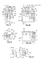
- FIGS 7 and 8 show a three-dot display assembly 10A which is similar in many respects to the assembly 10 of Figures 1 to 5, and corresponding parts are identically numbered.
- the stator 9A has a rectangular U-shaped stator frame 11A with a pair of end walls 14 , 16 joined to a base 12A.
- the stator 9A carries a rotor assembly 25A which is similar to the rotor assembly 25, except that the disk 32 is replaced by three disks 32A, 32B and 32C arranged as a unit 50 which is rectangularly in a U-shaped array as shown in Figures 7, 8 and 9.
- the disks 32A, 32B and 32C can be integrally joined at bends 51.
- Stay bars or plates 52 extend outwardly from opposed sides 27A and 57 of a rotary bar 26A, and are secured to inner sides 49 of the disks 32A, 32B and 32C.
- the inner sides 59 are always concealed while the outer sides 53A, 53B and 53C are the display sides of the rotary unit 50.
- Further stay bars or plates 60 are secured between the sides 27A, 57 of the rotary bar and inner end portions of disks 32A, 32B and 32C.
- the disks 32 are preferably round, or substantially so, to present display dots when viewed from the viewing direction V.
- the bar magnet 42 carried by the fin 38 is disposed on the side 39 of the bar 26A in the same manner as in the rotor 25.
- the three-disk rotor 25A is rotatably mounted by trunnions 28 on the end walls 14, 16 of frame 11A in the same manner as in assembly 10.
- the cores 20, 22 are mounted on the bracket or shelf 18 in the same manner as in the assembly 10.
- Identical coils 23 are wound on the cores 20, 22 for turning the rotor 25A when the coils, arranged as shown in Figure 15, are energized by external circuitry applied via terminals 43A, 43B, 43C, 43D.
- Figures 7 and 8 show rotor 25A in the third or central viewing position of the rotor 25A.
- the free ends of cores 20, 22 adjacent to the rotor 25A are oppositely polarized with S and N poles respectively. This causes the magnet 42 to stabilize axially in a plane perpendicular to the axes of the cores 20, 22.
- the N pole of magnet 42 is repelled by the N pole of the core 22 while the S pole of the magnet 42 is repelled by the S pole of the core 20.
- the rotor 25A will turn by 180 degrees to expose side 53C of disk 32C in viewing direction V. If the polarity of the core 22 is changed to N and the polarity of the core 20 is changed to S, the rotor 25A will turn by 90 degrees from either side position to the central position shown in Figures 7 and 8.
- the rotor 25 has been illustrated as having the side 53A perpendicular to the side 53B, and the side 53C also perpendicular to the side 53B, in practice in order to ensure that only one side is visible in the viewing position, the sides 53A and 53C may each be at an external angle with side 53B of more than 90 degrees, for example, 102 degrees. In this event the rotor 25 must rotate 102 degrees to expose any other adjacent side.
- the angle at which the rotor 25 is stopped may be set by one or more stops fixed to the end walls 14,16.
- the two-dot display assembly 10 of Figures 1 to 6 can easily and inexpensively be converted to the three-dot display assembly 10A of Figures 7 and 8, by simply replacing the flat disk 32 by the three-disk unit 50.
- the stators 9 and 9X are substantially identical.
- the resulting message sign can display messages in two different colours for two of the display disks in their respective viewing positions, while the third disk displays a ground colour in its viewing position.
- the disk or dot display assembly 10B shown in Figures 10 to 14 has a rotor 25B which is similar to the rotors 25 and 25A of the dot display assemblies 10 and 10A.
- the magnet 42 and the fin 38 of the rotors 25 and 25A are replaced by a single permanent bar magnet 42A attached to one side 34B of the single round disk 32Y on the bar 26.
- the bar magnet 42A extends radially outward of the disk 32Y coplanar with the side 34B.
- the N pole of the magnet is offset from the edge 32X of the disk 32Y.
- Other parts correspond to those of the rotor 25 and are identically numbered.
- the stator 9 of assembly 10B is identical to the stator 9 in assembly 10.
- Figure 12 shows the disk 32Y exposing a coloured side 36 in the viewing direction V in the same manner as in Figure 4.
- the magnetic cores 20 and 22 are magnetized with N and S poles respectively adjacent to the rotor 25B. This polarization of the poles is opposite from the S, N polarization of the poles shown in Figure 6 for obtaining the centre or edgewise position ot the disk 32.
- the N pole of magnet 42A is used, and the S pole is remote from the cores 20, 22.
- the N and S polarization of the cores 20, 22 is obtained by making a terminal 43A of the coil 23A, shown in Figure 15, positive and a terminal 43D of the coil 23D negative.
- the rotor 25B will turn by 180 degrees in a direction D to expose the side 34B to the viewing direction V. If both of the cores 20 and 22 are polarized with N poles adjacent to the rotor 25B, as shown in Figure 14, they will equally repel the N pole of the magnet 42A, and the rotor 25B will assume the third or central position where the disk 32Y is disposed parallel to the cores 20, 22, and the edge 32B is exposed to the viewing direction V. This central position will expose no colour and corresponds to the central position of the rotor 25A shown in Figures 7 and 8.
- a multiplicity of assemblies 10B can be mounted in a matrix to display dots of two different colours for opposite sides of the display disk 32Y, while the disks in edgewise position present no colour or blackness for background effect.
- Figures 16 and 17 illustrate a disk or dot assembly incorporating a modified form of rotor 25.
- the magnet 42 is held by the fin or tab 38 onto a rotatable drive member 61 which is mounted by trunnions 62 at opposite ends thereof in respective holes in the end wall 14 of the stator frame and a support bracket 63 integral with the end wall 14.
- the drive member 61 carries a gear 64 which meshes with a gear 65 mounted on a rotatable shaft 26C which carries a display unit 66.
- This display unit defines three display sides 66A, 66B, 66C in an equiangular triangular array about the rotor shaft 26C.
- the gearing ratio between the gears 64 and 65 is such that when the gear 64 is caused to rotate by a quarter of a turn the gear 65 will rotate by one-third of a turn.
- the display unit 66 will rotate through 120 degrees to display respective ones of the display sides 66A, 66B, 66C.
- the gears 64 and 65 may be replaced by other gearing mechanisms, including toothed belts and pulley arrangements.
Abstract
A dot display assembly has a three-position rotor (25) carrying a dot display disk (32) for use as a portion of a matrix of dots in a variable message sign. The assembly has a stator (9) including a support (18) carrying reversely magnetizable separate magnetic cores (20, 22) on which are separate electrically energizable coils (23). The rotor (25) which is carried by the support has a shaft (26) rotated axially perpendicular to the cores (20, 22). A permanent magnet (42) on the rotor (25) is adjacent to the cores (20, 22) to interact magnetically with them and rotate the shaft (26) selectively to any one of three rotor positions, by selective energization of the coils (23), the middle position being achieved by ensuring that the upper end of core (20) defines an S pole whilst the upper end of core (22) defines an N pole. The display disk (32) has a peripheral display edge (32X) and two opposite display sides (34, 36), and is mounted on the shaft (26) for selective display of said edge or either of the display sides in a viewing direction V. The disk (32) may be replaced by a unit of three disks providing three exposed display sides.
Description
- This invention relates to the art of dot display assemblies, useful as part of a large matrix of revolving disks which can serve as a variable message sign for a shopping mall, highway, theatre, restaurant, or other public viewing installation.
- Dot display assemblies now available are generally designed to present either one of two different display faces. These display assemblies utilize as a basic display element, a rotatable disk which is rotated through 180 degress by electromagnetic means actuated by appropriate electrical or electronic circuitry. The display disk usually has one black side and an opposite fluorescent coloured side and carries a permanent magnet. When the display disks in a matrix are selectively turned to a determined one of their two viewing positions different messages may be exhibited. Such a prior dot assembly may have a stationary U-shaped magnetic core on the two legs of which each may have one coil. The coils are each one half of a single continuous coil. When electric current passes through the coil in one direction, the cores present magnetic poles of opposite polarity to an adjacent rotatable disk, to turn the disk to one display position. When the coil current is reversed in direction, the magnetic polarities of the legs of the core reverse to turn the display disk to its other, second display position 180 degrees from the previous position. This type of prior dot display assembly is incapable of turning the disk to any additional dot display position.
- It is highly desirable, especially for advertising purposes, to provide a dot display assembly having three possible dot or disk display positions.
- According to the invention, there is provided a changeable dot display assembly for a portion of a matrix of dots in a variable message sign, comprising a stationary support, a pair of substantially parallel reversely magnetizable magnetic cores carried by said support, coils wound onto said cores to enable the same to be magnetized when said coils are electrically energized, and a rotor carried by said support, said rotor comprising a shaft mounted to rotate on an axis perpendicular to the axes of said cores and midway therebetween, a permanent magnet mounted to rotate so as to cause rotation of said shaft, said magnet having at least one magnetic pole disposed for attraction and repulsion by a magnetized end of at least one of said cores when said cores are magnetized by said coils, to rotate said rotor selectively to three diffferent positions with respect to a viewing position, and dot display means carried by said shaft, said display means having areas of different colours for selective display in said viewing position depending on the polarities of the ends of said cores when magnetized.
- In a first embodiment, said dot display means is a flat disk having opposed sides and a peripheral edge for selected disposition in said viewing position, whereby said shaft may be rotated in one direction to stop at a first place where one of said sides of said disk is exposed in said viewing position when said polarized ends of said cores have a first polarized array, said shaft may be rotated in an opposed direction to stop at a second place where the other side of said disk is exposed in said viewing position when said polarized ends of said cores have a second polarized array, and said shaft may be rotated in either direction to stop at a third place between said first place and said second place wherein said edge of said disk is exposed in said viewing position when said polarized ends of said cores have a third polarized array.
- In a further embodiment, said dot display means comprises a display unit having three display sides respectively disposable in said viewing position, a first one of said display sides being displayed in said viewing position when said polarized ends of said cores both have one polarized array, a second one of said display sides being displayed in said viewing position when said polarized ends of said cores both have a second polarized array, and a third one of said display sides being displayed in said viewing position when said polarized ends of said cores have a third polarized array. Ideally said display unit will comprise three disks, said display sides having mutually different colours for selective display thereof in said viewing position.
- With this further embodiment an advantageous modification is achieved by arranging that said permanent magnet is mounted on a rotatable drive member which is interconnected with said rotor shaft by a gearing drive which will cause said rotor to rotate to a greater extent than the rotation of said drive member. Then if the gearing ratio between said rotor shaft and said drive member is such that said rotor shaft will rotate by one-third of a full turn to one-quarter of a full turn of said drive member, the three display sides may be positioned in an equiangularly triangular array on the rotor shaft.
- Preferably the changeable dot assembly will incorporate a member secured to and extending from one side of said shaft adjacent said cores, said permanent magnet being carried by said member to rotate in a plane parallel to said axes of said cores to dispose opposite poles of said magnet for interaction with said polarized ends of said cores.
- The present invention thus employs a rotatable disk arrangement which is electromagnetically actuated to assume any selected one of three display positions. In the one preferred embodiment a single disk may be moved between two positions wherein different colours may be exhibited. In the third position a separate background of another colour may be exhibited. In the other preferred embodiment of the invention the rotatable disk has three dots or disks of different colours so that any one of the three dots of the display assembly may be selectively exhibited
- Both the single disk and the three-disk dot display assemblies employ a stator having a pair of stationary, separate, magnetic cores with separate coils wound on each of the cores. Each assembly has a rotor including a rotary bar which carries a display disk or disks with a permanent magnet attached thereto. The coils may be connected to an external d.c. voltage source so arranged that the cores are independently magnetized to attract or repel the permanent magnet and thereby to turn the rotor of the dot display member or members to any selected one of the three possible display positions. A multiplicity of such dot display assemblies embodying the invention may be arranged in a matrix to exhibit changeable messages in different colours. The three position dot display assembly may be provided at a very slight increase in cost or even at no increase in cost over a dot display assembly capable of providing only two display positions.
- The invention may be performed in various ways and preferred embodiments thereof will now be described with reference to the accompanying drawings, in which:-
- Figure 1 is a side view of a dot display assembly employing a single display disk according to the invention;
- Figure 2 is a top plan view of the dot display assembly of Figure 1;
- Figure 3 is an end elevational view taken along line 3-3 of Figure 1;
- Figure 4 is a vertical cross-sectional view taken along line 4-4 of Figure 1, showing the display disk in a first viewing position;
- Figures 5 and 6 are sectional views similar to Figure 4 showing the display disk in second and third viewing positions respectively;
- Figure 7 is a vertical sectional view similar to Figures 4 to 6, of another dot display assembly having three dot display disks;
- Figure 8 is a vertical, longitudinal sectional view taken along line 8-8 of Figure 7;
- Figure 9 is an isometric view of a rotor employed in the dot display assembly of Figures 7 and 8;
- Figure 10 is a side elevational view similar to Figure 1, showing a modified form of dot display assembly of the invention;
- Figure 11 is a top plan view of the dot display assembly of Figure 10;
- Figure 12 is a cross-sectional view taken along line 12-12 of Figure 10, showing the rotor in one selected dot display position;
- Figure 13 is a bottom plan view of the rotor of the dot display assembly of Figures 10 to 12;
- Figure 14 is a cross-sectional view similar to Figure 12, showing the rotor in another dot display position;
- Figure 15 is a circuit diagram of the cores and coils employed in the stators of the three dot display assemblies of Figures 1 to 14;
- Figure 16 is a side view of a still further embodiment of a dot display assembly according to the invention; and
- Figure 17 is a vertical cross-sectional view taken along line 17-17 of Figure 16.
- Referring now to the drawings, wherein like reference characters designate like or corresponding parts of the various embodiments, there is illustrated in Figures 1 to 6 a dot display assembly generally designated as
reference numeral 10 for a message sign matrix. Theassembly 10 has astator 9, including a stationary rectangularU-shaped stator frame 11 with astraight base 12, and twoupright end walls end wall 14 is a bracket orplatform 18 on which are mounted two stationary, straight,magnetizable cores cores identical wire coils 23 which coils may be wound with bifilar wire.Terminals 24 of thecoils 23 are to be connected to appropriate external circuitry for operating theassembly 10. - The
assembly 10 has arotor 25 including a rectangular shaft orbar 26 provided withtrunnions 28 at opposite ends thereof which are rotatably engaged inrespective holes 30 near free ends of theframe walls bar 26 rotates on its longitudinal axis parallel to thebase 12. Mounted on oneside 27 of thebar 26 is a flatcircular disk 32, oneside 34 of which may be coloured black or other ground colour to provide background view, whilst theother side 36 of thedisk 32 may have a different colour for use as part of a coloured message in a matrix of similar assemblies. Near one end of thebar 26 is a flat fin ortab 38 extending parallel to theside 27 and to thedisk 32 , from aside 39. Secured in ahole 40 in thefin 38 is a short, straight,magnet 42 permanently magnetized with opposed N and S poles. Themagnet 42 extends axially perpendicular to theside 27 of thebar 26 and parallel to theside 39. When therotor 25 turns, themagnet 42 rotates in a plane which includes the longitudinal axes of bothcores - Figure 15 shows the
cores coils 23 wound on them. It is preferred that the coils be wound with a bifilar winding.Windings core 20 andwindings 23C and 23D are wound on thecore 22. Thecoils 23 haveterminals cores common junction point 45. When theterminal 43A is positive and theterminal 43C is negative, then bothcores terminal 43B is positive and the terminal 43D is negative, then bothcores terminal 43B is positive and theterminal 43C is negative, then thecore 20 will have an S pole at its free end and thecore 22 will have an N pole at its free end. - In operation of the
dot display assembly 10 of Figures 1 to 6, when the free ends of both of themagnetic cores rotor 25, as indicated in Figure 4, the N pole of themagnet 42 will be attracted to the core 22 while the S pole of themagnet 42 will be repelled from thecore 20. Thedisplay disk 32 will therefore assume the position shown in Figure 4 where thecoloured display side 36 faces outwardly in the viewing direction V. When the currents magnetizing thecores cores rotor 25 stationary. When thereafter, the currents in thecoils 23 are directed as explained above, in connection with Figure 15, so that the N poles of both of thecores rotor 25, therotor 25 will turn counterclockwise by 180 degrees in the direction D1 from the Figure 4 position to the reversed position shown in Figure 5. Since themagnetized cores rotor 25, the N pole of the core 20 will attract the S pole of themagnet 42 while the N pole of the core 22 will repel the N pole of themagnet 42. Thus, the rotor will assume and remain in the position shown in Figure 5 where theside 34 of thedisk 32 is exposed outwardly in the viewing position while theside 36 is concealed. If the currents in thecoils 23 are now cut off thecores coils 23 are again reversed, therotor 25 will turn clockwise by 180 degrees in the direction D2 to the position illustrated in Figure 4 where the S pole of the core 22 again attracts the N pole of themagnet 42, while the S pole of thecore 20 repels the S pole of themagnet 42. - The sides of the bar or
shaft 26 should be coloured black or have the same ground colour as theside 34 of thedisk 32 to present a uniform appearance with theside 34 when it is exposed as shown in Figure 5. - If the currents in the
coils 23 are directed, as explained in connection with Figure 15, so that the poles of thecores rotor 25 assume polarities, such that one pole will be an S pole and the other pole will be an N pole, as shown in Figure 6, then both poles of therotor magnet 42 are repelled by the twocores rotor 25 to turn by 90 degrees so that themagnet 42 will be axially parallel to thebase 12 of theframe 11, and thedisk 32 will be disposed in a plane parallel to the axes of thecores edge 32X exposed. This constitutes a third display position of theassembly 10. - Figures 7 and 8 show a three-
dot display assembly 10A which is similar in many respects to theassembly 10 of Figures 1 to 5, and corresponding parts are identically numbered. Thestator 9A has a rectangularU-shaped stator frame 11A with a pair ofend walls base 12A. Thestator 9A carries arotor assembly 25A which is similar to therotor assembly 25, except that thedisk 32 is replaced by threedisks unit 50 which is rectangularly in a U-shaped array as shown in Figures 7, 8 and 9. Thedisks plates 52 extend outwardly fromopposed sides rotary bar 26A, and are secured to inner sides 49 of thedisks inner sides 59 are always concealed while theouter sides rotary unit 50. Further stay bars orplates 60 are secured between thesides disks disks 32 are preferably round, or substantially so, to present display dots when viewed from the viewing direction V. Thebar magnet 42 carried by thefin 38 is disposed on theside 39 of thebar 26A in the same manner as in therotor 25. The three-disk rotor 25A is rotatably mounted bytrunnions 28 on theend walls frame 11A in the same manner as inassembly 10. Thecores shelf 18 in the same manner as in theassembly 10.Identical coils 23 are wound on thecores rotor 25A when the coils, arranged as shown in Figure 15, are energized by external circuitry applied viaterminals - Figures 7 and 8
show rotor 25A in the third or central viewing position of therotor 25A. It will be noted that the free ends ofcores rotor 25A are oppositely polarized with S and N poles respectively. This causes themagnet 42 to stabilize axially in a plane perpendicular to the axes of thecores magnet 42 is repelled by the N pole of the core 22 while the S pole of themagnet 42 is repelled by the S pole of thecore 20. When therotor 25A initially turns to the central or third position shown in Figures 7 and 8, there may be some slight oscillation, but this will soon disappear or may not occur at all if the magnetization of thecores bar 26A midway between the cores. If the polarity of thecores cores rotor 25A themagnet 42 will assume the position shown in Figure 4, butdisplay side 53A ofdisk 32A will be exposed and exhibited in the viewing direction V. If the polarity of thepoles cores rotor 25A will turn by 180 degrees to exposeside 53C ofdisk 32C in viewing direction V. If the polarity of thecore 22 is changed to N and the polarity of thecore 20 is changed to S, therotor 25A will turn by 90 degrees from either side position to the central position shown in Figures 7 and 8. - Although the
rotor 25 has been illustrated as having theside 53A perpendicular to theside 53B, and theside 53C also perpendicular to theside 53B, in practice in order to ensure that only one side is visible in the viewing position, thesides side 53B of more than 90 degrees, for example, 102 degrees. In this event therotor 25 must rotate 102 degrees to expose any other adjacent side. The angle at which therotor 25 is stopped may be set by one or more stops fixed to theend walls - It will be noted that the two-
dot display assembly 10 of Figures 1 to 6 can easily and inexpensively be converted to the three-dot display assembly 10A of Figures 7 and 8, by simply replacing theflat disk 32 by the three-disk unit 50. Thestators 9 and 9X are substantially identical. - When a multiplicity of
display assemblies 10A are mounted in a matrix, the resulting message sign can display messages in two different colours for two of the display disks in their respective viewing positions, while the third disk displays a ground colour in its viewing position. - The disk or
dot display assembly 10B shown in Figures 10 to 14 has arotor 25B which is similar to therotors dot display assemblies magnet 42 and thefin 38 of therotors permanent bar magnet 42A attached to oneside 34B of thesingle round disk 32Y on thebar 26. Thebar magnet 42A extends radially outward of thedisk 32Y coplanar with theside 34B. The N pole of the magnet is offset from theedge 32X of thedisk 32Y. Other parts correspond to those of therotor 25 and are identically numbered. Thestator 9 ofassembly 10B is identical to thestator 9 inassembly 10. - Figure 12 shows the
disk 32Y exposing acoloured side 36 in the viewing direction V in the same manner as in Figure 4. It will be noted that in this position, themagnetic cores rotor 25B. This polarization of the poles is opposite from the S, N polarization of the poles shown in Figure 6 for obtaining the centre or edgewise position ot thedisk 32. Here, however, only the N pole ofmagnet 42A is used, and the S pole is remote from thecores cores coil 23A, shown in Figure 15, positive and a terminal 43D of the coil 23D negative. If the magnetic polarization of thecores core 20 and the N pole of the core 22 (as shown in Figure 6) are adjacent to therotor 25B, therotor 25B, will turn by 180 degrees in a direction D to expose theside 34B to the viewing direction V. If both of thecores rotor 25B, as shown in Figure 14, they will equally repel the N pole of themagnet 42A, and therotor 25B will assume the third or central position where thedisk 32Y is disposed parallel to thecores edge 32B is exposed to the viewing direction V. This central position will expose no colour and corresponds to the central position of therotor 25A shown in Figures 7 and 8. - It will be noted that no structural change is required in the
stator 9 to obtain rotation of therotor 25B to the three positions of thedot display asssembly 10B. The only change in operation is in the way in which the magnetizing voltages are applied to thecoils 23 as explained above with reference to Figure 15 . The threeposition assembly 10 can easily and inexpensively be converted to the construction of theassembly 10B simply by replacing themagnet 42 with themagnet 42A. This conversion or change will effect a saving in cost of assembly and reduction in the number and size of parts. - A multiplicity of
assemblies 10B can be mounted in a matrix to display dots of two different colours for opposite sides of thedisplay disk 32Y, while the disks in edgewise position present no colour or blackness for background effect. - Figures 16 and 17 illustrate a disk or dot assembly incorporating a modified form of
rotor 25. In this arrangement themagnet 42 is held by the fin ortab 38 onto arotatable drive member 61 which is mounted bytrunnions 62 at opposite ends thereof in respective holes in theend wall 14 of the stator frame and asupport bracket 63 integral with theend wall 14. Thedrive member 61 carries agear 64 which meshes with agear 65 mounted on arotatable shaft 26C which carries adisplay unit 66. This display unit defines threedisplay sides rotor shaft 26C. The gearing ratio between thegears gear 64 is caused to rotate by a quarter of a turn thegear 65 will rotate by one-third of a turn. Thus, as themagnet 42 moves between its three positions which are displaced from one another by 90 degrees, thedisplay unit 66 will rotate through 120 degrees to display respective ones of the display sides 66A, 66B, 66C. It will be appreciated that thegears - It should be understood that the foregoing relates to only a limited number of preferred embodiments of the invention which have been by way of example only and various changes and modifications to the examples illustrated may be made as may occur to those skilled in the art which do not constitute departuresfrom the spirit and scope of the invention as defined in the appended claims.
Claims (10)
1. A changeable dot display assembly for a portion of a matrix of dots in a variable message sign, comprising a stationary support, a pair of substantially parallel reversely magnetizable magnetic cores carried by said support, coils wound onto said cores to enable the same to be magnetized when said coils are electrically energized, and a rotor carried by said support, said rotor comprising a shaft mounted to rotate on an axis perpendicular to the axes of said cores and midway therebetween, a permanent magnet mounted to rotate so as to cause rotation of said shaft, said magnet having at least one magnetic pole disposed for attraction and repulsion by a magnetized end of at least one of said cores when said cores are magnetized by said coils, to rotate said rotor selectively to three diffferent positions with respect to a viewing position, and dot display means carried by said shaft, said display means having areas of different colours for selective display in said viewing position depending on the polarities of the ends of said cores when magnetized.
2. A changeable dot assembly as defined in claim 1, wherein said dot display means is a flat disk having opposed sides and a peripheral edge for selected disposition in said viewing position, whereby said shaft may be rotated in one direction to stop at a first place where one of said sides of said disk is exposed in said viewing position when said polarized ends of said cores have a first polarized array, said shaft may be rotated in an opposed direction to stop at a second place where the other side of said disk is exposed in said viewing position when said polarized ends of said cores have a second polarized array, and said shaft may be rotated in either direction to stop at a third place between said first place and said second place wherein said edge of said disk is exposed in said viewing position when said polarized ends of said cores have a third polarized array.
3. A changeable dot assembly as defined in claim 2, wherein said permanent magnet is mounted to dispose just one magnetic pole thereof adjacent said ends of said cores for selectively exposing said sides and said edge of said disk when the polarized array of said cores changes.
4. A changeable dot assembly as defined in claim 2 or claim 3, wherein said permanent magnet is disposed to rotate in a plane parallel to said axes of said cores, so that said shaft is rotatable selectively in two equal steps to expose one of said sides and said edge of said disk selectively in said viewing position for differing polarized arrays of said cores.
5. A changeable dot assembly as defined in claim 1, wherein said dot display means comprises a display unit having three display sides respectively disposable in said viewing position, a first one of said display sides being displayed in said viewing position when said polarized ends of said cores both have one polarized array, a second one of said display sides being displayed in said viewing position when said polarized ends of said cores both have a second polarized array, and a third one of said display sides being displayed in said viewing position when said polarized ends of said cores have a third polarized array.
6. A changeable dot assembly as defined in claim 5, wherein said display unit comprises three disks, said display sides having mutually different colours for selective display thereof in said viewing position.
7. A changeable dot assembly as defined in claim 5 or claim 6, wherein said permanent magnet is disposed to rotate in a plane parallel to said axes of said cores, so that said shaft is rotatable selectively to one of two other angular positions depending on the magnetic polarities of said ends of said cores, for selectively displaying any one of said three display sides in said viewing position.
8. A changeable dot assembly as defined in any one of claims 5 to 7, wherein said disks are integrally joined at adjacent edges, and further comprising support members connected between said shaft and facing inner sides of said disks to mount said display unit rigidly on said shaft.
9. A changeable dot assembly as defined in any one of claims 5 to 8, wherein said permanent magnet is mounted on a rotatable drive member which is interconnected with said rotor shaft by a gearing drive which will cause said rotor to rotate to a greater extent than the rotation of said drive member, and preferably the gearing ratio between said rotor shaft and said drive member is such that said rotor shaft will rotate by one-third of a full turn to one-quarter of a full turn of said drive member.
10. A changeable dot assembly as defined in any one of claims 1 to 9, further comprising a member secured to and extending from one side of said shaft adjacent said cores, said permanent magnet being carried by said member to rotate in a plane parallel to said axes of said cores to dispose opposite poles of said magnet for interaction with said polarized ends of said cores, and/or wherein said coils are each independent of each other, for selectively magnetizing said cores.
Applications Claiming Priority (2)
| Application Number | Priority Date | Filing Date | Title |
|---|---|---|---|
| US07/056,438 US4796368A (en) | 1987-06-01 | 1987-06-01 | Changeable dot display assembly |
| US56438 | 1987-06-01 |
Publications (1)
| Publication Number | Publication Date |
|---|---|
| EP0294151A1 true EP0294151A1 (en) | 1988-12-07 |
Family
ID=22004417
Family Applications (1)
| Application Number | Title | Priority Date | Filing Date |
|---|---|---|---|
| EP88304945A Withdrawn EP0294151A1 (en) | 1987-06-01 | 1988-05-31 | Improvements relating to changeable dot display assemblies |
Country Status (4)
| Country | Link |
|---|---|
| US (1) | US4796368A (en) |
| EP (1) | EP0294151A1 (en) |
| AU (1) | AU1696188A (en) |
| GB (1) | GB2206435A (en) |
Families Citing this family (3)
| Publication number | Priority date | Publication date | Assignee | Title |
|---|---|---|---|---|
| HU216240B (en) * | 1993-06-30 | 1999-09-28 | László Jáki | Passive element signal indicating arrangement, especially for indicating characters composed from agregations of image points arranged in matrix |
| CA2429831A1 (en) * | 2000-11-22 | 2002-05-30 | Flixel Ltd. | Microelectromechanical display devices |
| IL162194A0 (en) * | 2001-12-03 | 2005-11-20 | Flixel Ltd | Display devices |
Citations (4)
| Publication number | Priority date | Publication date | Assignee | Title |
|---|---|---|---|---|
| US3307170A (en) * | 1963-02-27 | 1967-02-28 | Fujitsu Ltd | Multi-face indicator system |
| EP0054336A1 (en) * | 1980-12-11 | 1982-06-23 | American Sign & Indicator Corporation | Matrix display |
| WO1984000839A1 (en) * | 1982-08-06 | 1984-03-01 | Harwal Ind Pty Limited | Coloured display |
| US4558529A (en) * | 1985-02-04 | 1985-12-17 | Nei Canada Limited | Display element with back lighting |
Family Cites Families (8)
| Publication number | Priority date | Publication date | Assignee | Title |
|---|---|---|---|---|
| US3540038A (en) * | 1969-07-31 | 1970-11-10 | Ferranti Packard Ltd | Multi-color single axis magnetically actuated display or indicating element |
| US3624941A (en) * | 1969-12-29 | 1971-12-07 | Ferranti Packard Ltd | Reversible sign element |
| US4380879A (en) * | 1980-12-11 | 1983-04-26 | American Sign & Indicator Corporation | Matrix display |
| JPS59192284A (en) * | 1983-04-15 | 1984-10-31 | 若竹 日方 | Rotary type display element and display unit using same |
| US4531318A (en) * | 1983-09-16 | 1985-07-30 | Nei Canada Limited | Display or indicating element with bent core |
| US4577427A (en) * | 1984-05-14 | 1986-03-25 | Nei Canada Limited | Display |
| US4627182A (en) * | 1985-06-03 | 1986-12-09 | Tempo Instrument Incorporated | Bi-stable display device |
| US4706398A (en) * | 1986-03-03 | 1987-11-17 | Nei Canada Limited | Multicolor indicator with arcuate pole pieces |
-
1987
- 1987-06-01 US US07/056,438 patent/US4796368A/en not_active Expired - Fee Related
-
1988
- 1988-05-27 GB GB08812730A patent/GB2206435A/en not_active Withdrawn
- 1988-05-31 EP EP88304945A patent/EP0294151A1/en not_active Withdrawn
- 1988-06-01 AU AU16961/88A patent/AU1696188A/en not_active Abandoned
Patent Citations (4)
| Publication number | Priority date | Publication date | Assignee | Title |
|---|---|---|---|---|
| US3307170A (en) * | 1963-02-27 | 1967-02-28 | Fujitsu Ltd | Multi-face indicator system |
| EP0054336A1 (en) * | 1980-12-11 | 1982-06-23 | American Sign & Indicator Corporation | Matrix display |
| WO1984000839A1 (en) * | 1982-08-06 | 1984-03-01 | Harwal Ind Pty Limited | Coloured display |
| US4558529A (en) * | 1985-02-04 | 1985-12-17 | Nei Canada Limited | Display element with back lighting |
Also Published As
| Publication number | Publication date |
|---|---|
| GB8812730D0 (en) | 1988-06-29 |
| GB2206435A (en) | 1989-01-05 |
| AU1696188A (en) | 1988-12-01 |
| US4796368A (en) | 1989-01-10 |
Similar Documents
| Publication | Publication Date | Title |
|---|---|---|
| EP0364258B1 (en) | Rotating display element and display unit using the same | |
| US4694599A (en) | Electromagnetic flip-type visual indicator | |
| JPH0833710B2 (en) | Color display element and color display unit | |
| US4769638A (en) | Color graphics information display | |
| US4327357A (en) | Magnetic indicator assembly | |
| EP0294151A1 (en) | Improvements relating to changeable dot display assemblies | |
| US4558529A (en) | Display element with back lighting | |
| US3260871A (en) | Step motor for use with an indicator | |
| GB1480417A (en) | Segmental readout device having magnetic circuit components | |
| EP0093600A2 (en) | Rotating display element and display unit using the same | |
| US3936818A (en) | Electromagnetic indicator having oppositely magnetized stamped magnetic cores | |
| JP2851841B2 (en) | Display device | |
| US3201785A (en) | Indicating device | |
| AU760452B2 (en) | Display device and array | |
| US3668700A (en) | Segmental readout device | |
| US4864264A (en) | Bistable toggling indicator | |
| US3979747A (en) | Control circuit for a character segment display assembly | |
| JP3114007B2 (en) | Magnetic reversal display | |
| JPH0317335Y2 (en) | ||
| US3973726A (en) | Electromagnetic indicator | |
| JPH05952Y2 (en) | ||
| JPH0962213A (en) | Polyhedral display element | |
| EP0218443A1 (en) | Rotating display element and display unit using the same | |
| JPS6335987B2 (en) | ||
| JPS609821Y2 (en) | display device |
Legal Events
| Date | Code | Title | Description |
|---|---|---|---|
| PUAI | Public reference made under article 153(3) epc to a published international application that has entered the european phase |
Free format text: ORIGINAL CODE: 0009012 |
|
| AK | Designated contracting states |
Kind code of ref document: A1 Designated state(s): AT BE CH DE ES FR GB GR IT LI LU NL SE |
|
| 17P | Request for examination filed |
Effective date: 19890523 |
|
| STAA | Information on the status of an ep patent application or granted ep patent |
Free format text: STATUS: THE APPLICATION IS DEEMED TO BE WITHDRAWN |
|
| 18D | Application deemed to be withdrawn |
Effective date: 19901201 |