EP0293639A2 - Device for acquisition, storage, and/or manipulation of amounts consumed - Google Patents
Device for acquisition, storage, and/or manipulation of amounts consumed Download PDFInfo
- Publication number
- EP0293639A2 EP0293639A2 EP88107420A EP88107420A EP0293639A2 EP 0293639 A2 EP0293639 A2 EP 0293639A2 EP 88107420 A EP88107420 A EP 88107420A EP 88107420 A EP88107420 A EP 88107420A EP 0293639 A2 EP0293639 A2 EP 0293639A2
- Authority
- EP
- European Patent Office
- Prior art keywords
- interface
- input
- counters
- unit
- devices
- Prior art date
- Legal status (The legal status is an assumption and is not a legal conclusion. Google has not performed a legal analysis and makes no representation as to the accuracy of the status listed.)
- Withdrawn
Links
Images
Classifications
-
- G—PHYSICS
- G01—MEASURING; TESTING
- G01D—MEASURING NOT SPECIALLY ADAPTED FOR A SPECIFIC VARIABLE; ARRANGEMENTS FOR MEASURING TWO OR MORE VARIABLES NOT COVERED IN A SINGLE OTHER SUBCLASS; TARIFF METERING APPARATUS; MEASURING OR TESTING NOT OTHERWISE PROVIDED FOR
- G01D4/00—Tariff metering apparatus
- G01D4/002—Remote reading of utility meters
- G01D4/004—Remote reading of utility meters to a fixed location
-
- G—PHYSICS
- G01—MEASURING; TESTING
- G01F—MEASURING VOLUME, VOLUME FLOW, MASS FLOW OR LIQUID LEVEL; METERING BY VOLUME
- G01F15/00—Details of, or accessories for, apparatus of groups G01F1/00 - G01F13/00 insofar as such details or appliances are not adapted to particular types of such apparatus
- G01F15/06—Indicating or recording devices
- G01F15/061—Indicating or recording devices for remote indication
- G01F15/063—Indicating or recording devices for remote indication using electrical means
-
- G—PHYSICS
- G01—MEASURING; TESTING
- G01F—MEASURING VOLUME, VOLUME FLOW, MASS FLOW OR LIQUID LEVEL; METERING BY VOLUME
- G01F15/00—Details of, or accessories for, apparatus of groups G01F1/00 - G01F13/00 insofar as such details or appliances are not adapted to particular types of such apparatus
- G01F15/07—Integration to give total flow, e.g. using mechanically-operated integrating mechanism
- G01F15/075—Integration to give total flow, e.g. using mechanically-operated integrating mechanism using electrically-operated integrating means
- G01F15/0755—Integration to give total flow, e.g. using mechanically-operated integrating mechanism using electrically-operated integrating means involving digital counting
-
- G—PHYSICS
- G01—MEASURING; TESTING
- G01R—MEASURING ELECTRIC VARIABLES; MEASURING MAGNETIC VARIABLES
- G01R21/00—Arrangements for measuring electric power or power factor
- G01R21/133—Arrangements for measuring electric power or power factor by using digital technique
-
- Y—GENERAL TAGGING OF NEW TECHNOLOGICAL DEVELOPMENTS; GENERAL TAGGING OF CROSS-SECTIONAL TECHNOLOGIES SPANNING OVER SEVERAL SECTIONS OF THE IPC; TECHNICAL SUBJECTS COVERED BY FORMER USPC CROSS-REFERENCE ART COLLECTIONS [XRACs] AND DIGESTS
- Y02—TECHNOLOGIES OR APPLICATIONS FOR MITIGATION OR ADAPTATION AGAINST CLIMATE CHANGE
- Y02B—CLIMATE CHANGE MITIGATION TECHNOLOGIES RELATED TO BUILDINGS, e.g. HOUSING, HOUSE APPLIANCES OR RELATED END-USER APPLICATIONS
- Y02B90/00—Enabling technologies or technologies with a potential or indirect contribution to GHG emissions mitigation
- Y02B90/20—Smart grids as enabling technology in buildings sector
-
- Y—GENERAL TAGGING OF NEW TECHNOLOGICAL DEVELOPMENTS; GENERAL TAGGING OF CROSS-SECTIONAL TECHNOLOGIES SPANNING OVER SEVERAL SECTIONS OF THE IPC; TECHNICAL SUBJECTS COVERED BY FORMER USPC CROSS-REFERENCE ART COLLECTIONS [XRACs] AND DIGESTS
- Y04—INFORMATION OR COMMUNICATION TECHNOLOGIES HAVING AN IMPACT ON OTHER TECHNOLOGY AREAS
- Y04S—SYSTEMS INTEGRATING TECHNOLOGIES RELATED TO POWER NETWORK OPERATION, COMMUNICATION OR INFORMATION TECHNOLOGIES FOR IMPROVING THE ELECTRICAL POWER GENERATION, TRANSMISSION, DISTRIBUTION, MANAGEMENT OR USAGE, i.e. SMART GRIDS
- Y04S20/00—Management or operation of end-user stationary applications or the last stages of power distribution; Controlling, monitoring or operating thereof
- Y04S20/30—Smart metering, e.g. specially adapted for remote reading
Definitions
- the invention relates to a device for recording, storing and / or influencing consumption meters with the features from the preamble of patent claim 1.
- Such devices are basically known, for example in the form of an electronic maximum work to which electricity meters can be permanently connected.
- the device not only stores the quantity pulses emitted by the meter, but it is also able, for example at the end of a measuring period, to compare the power mean value with the highest stored mean value of the current monthly reset period and to replace it when it is exceeded.
- the reading of the measured values can be read in the known device either by hand or by means of a portable so-called tariff device terminal, the latter being able to be connected by the operator in succession to a plurality of electricity meters, the readings being able to be stored, for example, in a memory designed as a small cassette .
- a disadvantage of the known device is that it must be permanently installed on counters and only the measurement results of these counters processed.
- Another disadvantage of the known device is that it can only be connected to pulse counters and maximum units.
- the object underlying the invention was to provide a device of the type specified in the preamble of claim 1, with which a central individual reading of meters of different types and for different media, which are installed at different locations on the site or in a building , is made possible. It should also be possible to supply control signals to the meters, i.e. For example, to enable parameterization with regard to meter reading and meter number after a meter replacement. Furthermore, it should be possible to check all lines of the connected meters for manipulation with regard to interruption and short-circuit and to record the meter information of all media even in the event of a power failure.
- Consumption meters for different media can be connected to the device according to the invention.
- Typical applications are, for example, electricity metering, gas metering, water metering, district heating metering, but also, for example, data acquisition from environmental protection stations.
- concentrated, error-free querying of the meter readings of different media is possible at one point, it being possible to connect different meter types, namely both pulse counters and serial metering devices.
- the connection to a data transmission network brings additional advantages through the simultaneous reading and control possibility of the consumption meters from a central office.
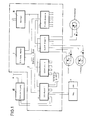
- Fig. 1 shows a block diagram of a device for recording, storing and / or influencing consumption meters, as can be set up, for example, in a larger building complex for reading all the consumption meters installed there.
- the device has a microcomputer 1 which is designed as a master module and from which the overall control of the device takes place.
- 2 input / output units are connected to the microcomputer 1 via data bus lines, namely several units 3.1 to 3.n designed as SIO modules, which are suitable for connecting different serial counting devices and several units 4.1 to 4.m designed as slave modules that are suitable for connecting pulse counters.
- each of the units 3.1 to 3.n can have four inputs / outputs and each of the units 4.1 to 4.m can be provided with 16 connections.
- connection options are only shown as examples. Appropriate devices can of course be connected to the reserved outputs.
- an electricity meter 5 is connected to the input / output unit 3.1, specifically via a maximum unit that outputs serial data.
- a second meter of this type can be connected to the same unit.
- Interface 10 for connecting the device to a data transmission network and an interface 9 for connecting an input / output terminal, which is designed as an optoelectronic interface.
- the units 4.1 to 4.m each contain a microcomputer and, for example, up to 16 pulse counters can be connected to each of the units. In this way, the microcomputer 1 is relieved when the number of counters is high.
- the operating voltage is supplied to the individual parts of the device from a power supply unit 11.
- Additional voltage supply devices for example accumulators, are arranged in the units, which enable the counting pulses to be processed even in the event of a limited power failure, for example in the event of a downtime of one hour. If the power supply 11 is buffered, remote data transmission and the supply of changeover signals can also take place in the event of a power failure.
- these units contain devices for line monitoring for short-circuit or line interruption, which perform a line check at regular intervals.
- a counter Zener diode D1 and a further Zener diode D2 are connected in parallel in the counters 6, 7 and 8 to the pulse-giving contacts.
- the predetermined voltage values that result as a result when the contacts are closed and open are monitored at predetermined time intervals.
- the operation of the device that is to say the reading and storage of data and the parameterization, is possible on site by connecting a corresponding input / output terminal to the interface 9.
- the corresponding reading and control processes take place via the interface 10.
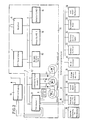
- FIG. 2 shows an extension of the device according to FIG. 1.
- the parts of the device according to FIG. 2 that are identical to corresponding device parts according to FIG. 1 are designated in FIG. 2 with the same reference number as in FIG. 1.
- the device according to FIG. 2 consists of a basic module 15, which can be arranged, for example, in a central building of a group of buildings, for reading all of the consumption meters installed there.
- the microcomputer 1 is arranged in the basic module 15, to which 2 input / output units are connected via data bus lines.
- the units designed as an SIO module only one unit 3.1 is shown in FIG. 2, which is suitable for connecting different serial counting devices.
- FIG. 2 is suitable for connecting pulse counters 6, 7 and 8.
- a unit 12 which is called “Maxi mum interface module 1 ".
- power meters with serial data output can be connected.
- a unit 13 which is referred to as “signal slave 1” and a unit 14, which is referred to as “command slave 1" are connected in the basic module. Additional data can be transmitted to the microcomputer 1 via the unit 13 from devices which emit binary values (operating states) and provide information, or else through manipulations on other connected devices.
- the unit 14 transmits data from the microcomputer 1 to other connected devices, for example commands to switch off systems in the event of late payment or to switch on emergency power devices.
- the basic module 15 is supplemented by a series of expansion modules which can be arranged, for example, in other buildings and which are connected to the unit 3.1 in the basic module 15 via a serial data bus 17 and an interface 16.
- the same devices can be connected to the data bus 17 that are connected to the data bus 2 within the basic module 15.
- additional devices can be installed here.
- the maximum module is able, for example at the end of a measurement period, to compare the average power value with the highest stored average value of the current monthly reset period and to replace the excess value; a unit 20 which, like the unit 4.1, is designed as a slave module for receiving further count values supplied by pulse counters; a unit 21, which is designed analogously to the unit 12 as a maximum interface module; a unit 22, which is designed analogously to the unit 13 as a reporting slave; a unit 23, which is designed analogously to the unit 14 as a command slave; a unit 24, which can be designed as a module for local display of consumption values; a unit 25, which is referred to as a "logging module” and can be designed, for example, as a printer or writer; a unit 26, which is referred to as "ADC module measured values” and can be connected to the devices, which measured values of physical quantities such as pressure, temperature and. Form and the like in analog form to the unit 26, where they are converted into serial data.
- a unit 20 which, like the unit 4.1, is designed
Abstract
Description
Die Erfindung betrifft eine Einrichtung zur Erfassung, Speicherung und/oder Beeinflussung von Verbrauchszählern mit den Merkmalen aus dem Oberbegriff des Patentanspruches 1.The invention relates to a device for recording, storing and / or influencing consumption meters with the features from the preamble of
Derartige Einrichtungen sind grundsätzlich bekannt, beispielsweise in der Form eines elektronischen Maximumwerkes, an das Elektrizitätszähler fest angeschlossen werden können. Die Einrichtung speichert nicht nur die vom Zähler abgegebenen Mengenimpulse, sondern sie ist auch in der Lage beispielsweise am Ende einer Meßperiode den Leistungsmittelwert mit dem höchsten gespeicherten Mittelwert der laufenden monatlichen Rückstellperiode zu vergleichen und diesen bei Überschreitung zu ersetzen. Das Ablesen der Meßwerte kann bei der bekannten Einrichtung entweder von Hand oder mittels eines tragbaren sogenannten Tarifgeräte-Terminals abgelesen werden, wobei letzteres von der Bedienungsperson nacheinander an mehrere Elektrizitätszähler angeschlossen werden kann, wobei die abgelesenen Werte beispielsweise in einem als Kleinkassette ausgebildeten Speicher festgehalten werden können. Weiterhin ist es auch möglich, die bekannte Einrichtung über eine serielle Datenschnittstelle an ein Netz zur Datenfernübertragung anzuschließen.Such devices are basically known, for example in the form of an electronic maximum work to which electricity meters can be permanently connected. The device not only stores the quantity pulses emitted by the meter, but it is also able, for example at the end of a measuring period, to compare the power mean value with the highest stored mean value of the current monthly reset period and to replace it when it is exceeded. The reading of the measured values can be read in the known device either by hand or by means of a portable so-called tariff device terminal, the latter being able to be connected by the operator in succession to a plurality of electricity meters, the readings being able to be stored, for example, in a memory designed as a small cassette . Furthermore, it is also possible to connect the known device to a network for remote data transmission via a serial data interface.
Ein Nachteil der bekannten Einrichtung besteht darin, daß sie jeweils an Zählern fest installiert werden muß und auch nur jeweils die Meßergebnisse diese Zähler verarbeitet. Ein weiterer Nachteil der bekannten Einrichtung besteht darin, daß sie nur an Impulszähler und Maximumwerke angeschlossen werden kann.A disadvantage of the known device is that it must be permanently installed on counters and only the measurement results of these counters processed. Another disadvantage of the known device is that it can only be connected to pulse counters and maximum units.
Die der Erfindung zugrunde liegende Aufgabe bestand darin, eine Einrichtung der im Oberbegriff des Patentanspruchs 1 angegebenen Art zu schaffen, mit der eine zentrale Einzelablesung von Zählern unterschiedlichen Typs und für unterschiedliche Medien, die an verschiedenen Orten auf dem Gelände bzw. in einem Gebäude installiert sind, ermöglicht wird. Hierbei sollte es zusätzlich möglich sein, den Zählern Ansteuersignale zuzuführen, d.h. beispielsweise eine Parametrierbarkeit hinsichtlich Zählerstand und Zählernummer nach einem Zählertausch zu ermöglichen. Weiterhin sollte die Kontrolle aller Leitungen der angeschlossenen Zähler auf Manipulation bezüglich Unterbrechung und Kurzschluß sowie eine Erfassung der Zählerinformationen aller Medien auch bei Netzausfall möglich sein. Schließlich sollte es möglich sein, die Einrichtung an ein Datenübertragungsnetz anzuschließen, so daß sowohl die Ablesung aller angeschlossenen Zählereinrichtungen zur gleichen Zeit von einer Zentrale aus der Ferne erfolgen kann und daß andererseits ebenfalls zentral aus der Ferne Steuersignale zum Sperren und Freischalten sowie zur Rückstellung, zur Tarifschaltung, zur Laststeuerung usw. zugeführt werden können.The object underlying the invention was to provide a device of the type specified in the preamble of
Die Lösung dieser Aufgabe erfolgt mit den Merkmalen aus dem kennzeichnenden Teil des Patentanspruchs 1.This object is achieved with the features from the characterizing part of
Vorteilhafte Ausführungsformen der erfindungsgemäßen Einrichtung sind in den Unteransprüchen beschrieben.Advantageous embodiments of the device according to the invention are described in the subclaims.
An die erfindungsgemäße Einrichtung sind Verbrauchszähler für unterschiedliche Medien anschließbar. Typische Anwendungsfälle sind beispielsweise die Stromzählung, die Gaszählung, die Wasserzählung, die Fernwärmezählung, aber auch beispielsweise die Datenerfassung von Umweltschutzstationen. Bei einer Installierung der Einrichtung vor Ort ist die konzentrierte fehlerfreie Abfrage der Zählerstände unterschiedlicher Medien an einer Stelle möglich, wobei unterschiedliche Zählertypen, nämlich sowohl Impulszähler als auch serielle Zähleinrichtungen angeschlossen werden können. Der Anschluß an ein Datenübertragungsnetz bringt zusätzliche Vorteile durch die gleichzeitige Ablese- und Ansteuermöglichkeit der Verbrauchszähler von einer Zentrale aus.Consumption meters for different media can be connected to the device according to the invention. Typical applications are, for example, electricity metering, gas metering, water metering, district heating metering, but also, for example, data acquisition from environmental protection stations. When the device is installed on site, concentrated, error-free querying of the meter readings of different media is possible at one point, it being possible to connect different meter types, namely both pulse counters and serial metering devices. The connection to a data transmission network brings additional advantages through the simultaneous reading and control possibility of the consumption meters from a central office.
Es ist weiterhin möglich, die erfindungsgemäße Einrichtung zu erweitern, indem an die als Grundmodul ausgebildete, beispielsweise in einem Gebäude angeordnete Einrichtung, über eine zusätzliche Schnittstelle ein serieller Datenbus angeschlossen ist (s. Anspruch 5), an den weitere räumlich verzweigte, beispielsweise in anderen Gebäuden installierte Informationsquellen und/-oder -senken angeschlossen sind.It is also possible to expand the device according to the invention by connecting a serial data bus to the device designed as a basic module, for example arranged in a building, via an additional interface (see claim 5), to which further spatially branched devices, for example in others Information sources and / or sinks installed in buildings are connected.
Im folgenden werden anhand der beigefügten Zeichnungen zwei Ausführungsbeispiele für eine Einrichtung nach der Erfindung näher erläutert.Two exemplary embodiments of a device according to the invention are explained in more detail below with reference to the accompanying drawings.
In den Zeichnungen zeigen:
- Fig. 1 in einem Blockschaltbild eine Einrichtung zur Erfassung, Speicherung und/oder Beeinflussung von Verbrauchszählern;
- Fig. 2 in einer Darstellung analog Fig. 1 eine Erweiterung der Einrichtung nach Fig. 1.
- Figure 1 is a block diagram of a device for recording, storing and / or influencing consumption meters.
- 2 in a representation analogous to FIG. 1, an extension of the device according to FIG. 1.
Fig. 1 zeigt in einem Blockschaltbild eine Einrichtung zur Erfassung, Speicherung und/oder Beeinflussung von Verbrauchszählern, wie sie beispielsweise in einem größeren Gebäudekomplex zur Ablesung sämtlicher dort installierten Verbrauchszähler aufgestellt werden kann. Die Einrichtung besitzt einen Mikrocomputer 1, der als Master-Modul ausgebildet ist und von dem aus die Gesamtsteuerung der Einrichtung erfolgt. An den Mikrocomputer 1 sind über Datenbusleitungen 2 Ein/Ausgabeeinheiten angeschlossen, und zwar mehrere als SIO-Modul ausgebildete Einheiten 3.1 bis 3.n, die zum Anschluß von unterschiedlichen seriellen Zähleinrichtungen geeignet sind und mehrere als Slave-Modul ausgebildete Einheiten 4.1 bis 4.m, die zum Anschluß von Impulszählern geeignet sind.Fig. 1 shows a block diagram of a device for recording, storing and / or influencing consumption meters, as can be set up, for example, in a larger building complex for reading all the consumption meters installed there. The device has a
Die Einheiten sind so ausgelegt, daß jeweils mehrere Geräte anschließbar sind. So kann beispielsweise jede der Einheiten 3.1 bis 3.n vier Ein/Ausgänge aufweisen und jede der Einheiten 4.1 bis 4.m kann mit 16 Anschlüssen versehen sein.The units are designed so that several devices can be connected. For example, each of the units 3.1 to 3.n can have four inputs / outputs and each of the units 4.1 to 4.m can be provided with 16 connections.
In der Zeichnung sind jeweils nur beispielhaft einige Anschlußmöglichkeiten ausgeführt. Selbstverständlich können an die freigehaltenen Ausgänge entsprechende Geräte angeschlossen sein.In the drawing, some connection options are only shown as examples. Appropriate devices can of course be connected to the reserved outputs.
So ist beispielsweise an die Ein/Ausgabeeinheit 3.1 ein Elektrizitätszähler 5 angeschlossen, und zwar über ein Maximumwerk, das serielle Daten abgibt. An die gleiche Einheit kann noch ein zweiter Zähler dieses Typs angeschlossen werden. Weiterhin ist an diese Einheit eine Schnittstelle 10 zum Anschluß der Einrichtung an ein Datenübertragungsnetz angeschlossen und eine Schnittstelle 9 zum Anschluß eines Ein/Ausgabeterminals, die als optoelektronische Schnittstelle ausgebildet ist.For example, an
An die Einheit 4.1 sind als Beispiel drei Impulszähler für unterschiedliche Medien angeschlossen, nämlich ein Zähler 6 für Gas, ein Zähler 7 für Wasser und ein Zähler 8 für Fernwärme. Die von diesen Zählern abgegebenen binären Signale werden im Slave-Modul verarbeitet. Die Einheiten 4.1 bis 4.m enthalten jeweils einen Mikrocomputer und an jede der Einheiten können beispielsweise bis zu 16 Impulszähler angeschlossen werden. Auf diese Weise wird eine Entlastung des Mikrocomputers 1 bei hoher Zähleranzahl erreicht. Von einem Netzteil 11 aus wird den einzelnen Teilen der Einrichtung die Betriebsspannung zugeführt. In den Einheiten sind zusätzliche Spannungsversorgungsvorrichtungen, beispielsweise Akkumulatoren, angeordnet, die er ermöglichen, eine Verarbeitung der Zählimpulse auch bei begrenztem Netzausfall, beispielsweise bei einer Ausfallzeit von einer Stunde, durchzuführen. Wenn der Netzteil 11 gepuffert ausgeführt ist, kann bei einem Netzausfall auch eine Datenfernübertragung und eine Zuführung von Umsteuersignalen erfolgen. Weiterhin enthalten diese Einheiten Vorrichtungen zur Leitungsüberwachung auf Kurzschluß- oder Leitungsunterbrechung, die in regelmäßigen Zeitabständen eine Überprüfung der Leitungen vornehmen.As an example, three pulse counters for different media are connected to the unit 4.1, namely a
Um diese Überprüfung zu ermöglichen, sind in den Zählern 6, 7 und 8 den impulsgebenden Kontakten jeweils eine Zenerdiode D1 vorgeschaltet und eine weitere Zenerdiode D2 parallel geschaltet. Die sich dadurch bei geschlossenen und geöffneten Kontakten einstellenden vorgegebenen Spannungswerte werden in vorgegebenen Zeitabständen überwacht.To enable this check, a counter Zener diode D1 and a further Zener diode D2 are connected in parallel in the
Die Bedienung der Einrichtung, also das Ablesen und Ausspeichern von Daten, sowie das Parametrieren, ist vor Ort möglich, indem an die Schnittstelle 9 ein entsprechendes Ein/Ausgabeterminal angeschlossen wird. Bei Fernbedienung erfolgen die entsprechenden Ablese- und Steuervorgänge über die Schnittstelle 10.The operation of the device, that is to say the reading and storage of data and the parameterization, is possible on site by connecting a corresponding input / output terminal to the
Fig. 2 zeigt eine Erweiterung der Einrichtung nach Fig. 1. Die Teile der Einrichtung nach Fig. 2, die mit entsprechenden Einrichtungsteilen nach Fig. 1 identisch sind, sind in Fig. 2 mit der gleichen Bezugsziffer wie in Fig. 1 bezeichnet.FIG. 2 shows an extension of the device according to FIG. 1. The parts of the device according to FIG. 2 that are identical to corresponding device parts according to FIG. 1 are designated in FIG. 2 with the same reference number as in FIG. 1.
Die Einrichtung nach Fig. 2 besteht aus einem Grundmodul 15, das beispielsweise in einem zentralen Gebäude einer Gruppe von Gebäuden angeordnet sein kann, zur Ablesung sämtlicher dort installierter Verbrauchszähler. Wie bereits beschrieben, ist im Grundmodul 15 der Mikrocomputer 1 angeordnet, an den über Datenbusleitungen 2 Ein/Ausgabeeinheiten angeschlossen sind. Von den als SIO-Modul ausgebildeten Einheiten ist in Fig. 2 nur eine Einheit 3.1 dargestellt, die zum Anschluß von unterschiedlichen seriellen Zähleinrichtungen geeignet ist.The device according to FIG. 2 consists of a
Selbstverständlich können mehrere derartiger Einheiten vorgesehen sein.Of course, several such units can be provided.
Von den als Slave-Modul ausgebildeten Einheiten ist in Fig. 2 ebenfalls nur eine Einheit 4.1 dargestellt, die zum Anschluß von Impulszählern 6, 7 und 8 geeignet ist.Of the units designed as slave modules, only one unit 4.1 is also shown in FIG. 2, which is suitable for connecting
Auch hier können mehrere derartiger Einheiten vorhanden sein. Zusätzlich zu diesen Einheiten sind an den Datenbus 2 noch angeschlossen eine Einheit 12, die als "Maxi mum-Interface-Modul 1" bezeichnet ist. An die Einheit 12 sind Leistungsmeßwerke mit seriellem Datenausgang anschließbar.Several such units can also be present here. In addition to these units, a
Weiterhin sind im Grundmodul eine Einheit 13, die als "Melde-Slave 1" bezeichnet ist und eine Einheit 14, die als "Befehls-Slave 1" bezeichnet ist, angeschlossen. Über die Einheit 13 sind zusätzliche Daten an den Mikrocomputer 1 übertragbar von Geräten aus, die binäre Werte (Betriebszustände) abgeben und Informationen liefern, oder auch über Manipulationen an anderen angeschlossenen Geräten. Über die Einheit 14 werden Daten vom Mikrocomputer 1 aus an andere angeschlossene Geräte übermittelt, beispielsweise Befehle zur Abschaltung von Anlagen bei Zahlungsverzug oder zur Einschaltung von Notstromeinrichtungen.Furthermore, a
Das Grundmodul 15 ist durch eine Reihe von Erweiterungsmodulen ergänzt, die beispielsweise in anderen Gebäuden angeordnet sein können und die über einen seriellen Datenbus 17 und eine Schnittstelle 16 an die Einheit 3.1 im Grundmodul 15 angeschlossen sind.The
An den Datenbus 17 können im Prinzip die gleichen Einrichtungen angeschlossen sein, die innerhalb des Grundmoduls 15 an den Datenbus 2 angeschlossen sind. Es können hier aber noch zusätzliche Vorrichtungen installiert werden.In principle, the same devices can be connected to the
So können beispielsweise folgende, nur beispielhaft aufgezählte zusätzliche Einheiten vorhanden sein:
Eine Einheit 18 zur Speichererweiterung des Moduls (Einheit) 19;
eine Einheit 19 ist ein Maximum-Modul und übt die Funktionen wie das in der Fig. 1 dargestellte Maximumwerk aus. An die Einheit 19 werden Impulszähler angeschlossen. Das Maximum-Modul ist in der Lage, beispielsweise am Ende einer Meßperiode, den Leistungsmittelwert mit dem höchsten gespeicherten Mittelwert der laufenden monatlichen Rückstellperiode zu vergleichen und diesen die Überschreitung zu ersetzen;
eine Einheit 20, die analog der Einheit 4.1 als Slave-Modul ausgebildet ist zur Aufnahme weiterer von Impulszählern gelieferter Zählwerte;
eine Einheit 21, die analog der Einheit 12 als Maximum-Interface-Modul ausgebildet ist;
eine Einheit 22, die analog der Einheit 13 als Melde-Slave ausgebildet ist;
eine Einheit 23, die analog der Einheit 14 als Befehls-Slave ausgebildet ist;
eine Einheit 24, die als Modul für örtliche Anzeige von Verbrauchswerten ausgebildet sein kann;
eine Einheit 25, die als "Protokollier-Modul" bezeichnet ist und beispielsweise als Drucker oder Schreiber ausgebildet sein kann;
eine Einheit 26, die als "ADU-Modul-Meßwerte" bezeichnet ist und an die Geräte angeschlossen sein können, welche Meßwerte physikalischer Größen, wie beispielsweise Druck, Temperatur u. dgl. bilden und diese in analoger Form an die Einheit 26 weitergeben, wo sie in serielle Daten umgewandelt werden.For example, the following additional units, listed only as examples, may be present:
A
a
a
a
a
a
a
a
a
Es ist weiterhin möglich, anstelle der bekannten Maximumwerke, die im Viertelstundentakt Meßwerte abspeichern, Einheiten vorzusehen, die zum Zwecke der Leistungserfassung innerhalb bestimmter Zeiträume mit anderen, beispielsweise vorgebbaren Abfragetakten arbeiten, also etwa in einem 100 Stunden-Takt arbeiten.It is also possible, instead of the known maximum works, which store measured values every quarter of an hour, to provide units which, for the purpose of recording power, work with other, for example, predeterminable query cycles within certain time periods, that is to say work approximately every 100 hours.
Claims (5)
Applications Claiming Priority (2)
| Application Number | Priority Date | Filing Date | Title |
|---|---|---|---|
| DE3716019 | 1987-05-14 | ||
| DE19873716019 DE3716019A1 (en) | 1987-05-14 | 1987-05-14 | DEVICE FOR DETECTING, STORING AND / OR INFLUENCING CONSUMPERS |
Publications (2)
| Publication Number | Publication Date |
|---|---|
| EP0293639A2 true EP0293639A2 (en) | 1988-12-07 |
| EP0293639A3 EP0293639A3 (en) | 1990-09-05 |
Family
ID=6327471
Family Applications (1)
| Application Number | Title | Priority Date | Filing Date |
|---|---|---|---|
| EP19880107420 Withdrawn EP0293639A3 (en) | 1987-05-14 | 1988-05-09 | Device for acquisition, storage, and/or manipulation of amounts consumed |
Country Status (2)
| Country | Link |
|---|---|
| EP (1) | EP0293639A3 (en) |
| DE (1) | DE3716019A1 (en) |
Cited By (8)
| Publication number | Priority date | Publication date | Assignee | Title |
|---|---|---|---|---|
| GB2231668A (en) * | 1989-05-16 | 1990-11-21 | Compania Para La Fabricacion D | Remote reading and cutoff system for domestic gas meters |
| EP0458995A1 (en) * | 1990-05-29 | 1991-12-04 | Siemens Aktiengesellschaft | Measuring device for detecting, processing and displaying of data concerning flow quantities of liquids, gasses or electrical currents |
| WO1991019201A2 (en) * | 1990-06-06 | 1991-12-12 | M.T. Mcbrian Company, Inc. | System and method for monitoring and analyzing energy characteristics |
| EP0945711A1 (en) * | 1998-03-23 | 1999-09-29 | Tekno & Logic S.r.l. | System for recording consumption of a fluid |
| EP0949759A1 (en) * | 1998-04-09 | 1999-10-13 | Electrowatt Technology Innovation AG | Apparatus for generating an output voltage from an input voltage in an electricity meter, a remote control receiver, a combination of both and/or an additional device for use therewith, the output signal having a defined level which is independent from the level of the input signal |
| WO2000003209A2 (en) * | 1998-07-13 | 2000-01-20 | Houri, Rachid | Method and device for displaying various parameters concerning water consumption in a supply conduit |
| DE19922603A1 (en) * | 1999-05-17 | 2000-11-23 | Elster Produktion Gmbh | Method and device for reading a consumer meter by a remote instrument is fitted with a remote instrument reading module to record consumption electronically and to pass on a data remote transmission link to a data pick-up device. |
| EP3029431A1 (en) | 2014-12-04 | 2016-06-08 | GWF MessSysteme AG | Meter and method for determining meter readings and method for the wireless transmission of electrical energy |
Families Citing this family (17)
| Publication number | Priority date | Publication date | Assignee | Title |
|---|---|---|---|---|
| DE9002649U1 (en) * | 1990-03-07 | 1990-05-10 | Heidelberger Druckmaschinen Ag, 6900 Heidelberg, De | |
| DE4235187A1 (en) * | 1992-10-19 | 1994-04-21 | Metrona Waermemesser Union | Device for reading consumption values occurring in a building |
| DE19502685A1 (en) * | 1995-01-28 | 1996-08-01 | Sel Alcatel Ag | Representing performance on screen of computer or outputting from printer e.g. for number of sales etc. of products |
| DE19527702A1 (en) * | 1995-07-28 | 1997-01-30 | Kundo Systemtechnik Gmbh | Measurement data processing computer for through-flow or heat amount units - has unit assembly in own housing arranged by measurement value transmitter for flow or for flow and temp. difference with housing structurely separated |
| DE29515869U1 (en) * | 1995-10-08 | 1995-12-21 | Bauer Franz Hans Peter | Device for the controlled cashless delivery of electrical energy, gas, water or similar media |
| DE29520635U1 (en) * | 1995-12-28 | 1996-09-19 | Tils Gerda | Flow measurement device for liquids, especially water |
| DE19644873A1 (en) * | 1996-10-29 | 1998-04-30 | Jens Effert | Reset device for electronic counters, e.g. vehicle mileometer, operation timers |
| DE19701008A1 (en) * | 1997-01-14 | 1998-07-16 | Goerlitz Computerbau Gmbh | Data acquisition system and device for selecting and displaying time variable values |
| DE19702878A1 (en) * | 1997-01-28 | 1998-07-30 | Stepper & Co | Decentralised measurement device |
| DE19704492A1 (en) * | 1997-02-07 | 1998-08-20 | Endys Gmbh | Meter data reading and processing method |
| DE29710249U1 (en) * | 1997-06-12 | 1998-10-08 | Raab Karcher Energy Services G | Device for recording and evaluating temperature-dependent consumption values |
| DE19754675A1 (en) * | 1997-12-10 | 1999-07-01 | Klaus Dipl Ing Weber | Domestic utility usage recording and billing apparatus for electricity, water, telecommunications etc. |
| DE19834009A1 (en) * | 1998-07-28 | 2000-02-24 | Micro Sensys Gmbh | Method to detect and confirm gas, water and electricity meters; uses data carrier, e.g. transponder, integrated on chip to provide computer with data from meter |
| DE10014955A1 (en) * | 2000-03-22 | 2001-10-11 | Enerlyt Potsdam Gmbh En Umwelt | M-bus slave with data communications device e.g. for remote read-out of consumption/demand meters and counters, uses slave unit for providing remote data transmission into external data networks |
| DE10033237A1 (en) * | 2000-07-10 | 2002-01-24 | Abb Patent Gmbh | Consumed energy detection and display method involves determining preset value for energy to be consumed, and comparing it with actual amount of consumed energy |
| DE10055977A1 (en) * | 2000-11-11 | 2002-05-23 | Heinz Grueterich | Method for measuring and evaluating energy use for a company or private household that allows total carbon dioxide production to be determined with a reducing contribution acknowledged for use of renewable energy |
| DE10210365A1 (en) * | 2002-03-08 | 2003-10-02 | Ruediger Krause | Electricity meter reader unit detects rotations of the meter disk using an optical sensor arrangement linked to a microprocessor so that instantaneous and cumulative consumption can be measured and displayed |
Citations (4)
| Publication number | Priority date | Publication date | Assignee | Title |
|---|---|---|---|---|
| WO1981000619A1 (en) * | 1979-08-21 | 1981-03-05 | B Karlsson | A device for central reading and registration of customers'power consumption |
| JPS6065643A (en) * | 1983-09-20 | 1985-04-15 | Nec Corp | Exchange of two optical loops |
| JPS6123451A (en) * | 1984-07-11 | 1986-01-31 | Ricoh Co Ltd | Communication controller |
| EP0214915A2 (en) * | 1985-09-11 | 1987-03-18 | Alcatel N.V. | Information collecting and forwarding apparatus and method of operating such an apparatus |
-
1987
- 1987-05-14 DE DE19873716019 patent/DE3716019A1/en not_active Withdrawn
-
1988
- 1988-05-09 EP EP19880107420 patent/EP0293639A3/en not_active Withdrawn
Patent Citations (4)
| Publication number | Priority date | Publication date | Assignee | Title |
|---|---|---|---|---|
| WO1981000619A1 (en) * | 1979-08-21 | 1981-03-05 | B Karlsson | A device for central reading and registration of customers'power consumption |
| JPS6065643A (en) * | 1983-09-20 | 1985-04-15 | Nec Corp | Exchange of two optical loops |
| JPS6123451A (en) * | 1984-07-11 | 1986-01-31 | Ricoh Co Ltd | Communication controller |
| EP0214915A2 (en) * | 1985-09-11 | 1987-03-18 | Alcatel N.V. | Information collecting and forwarding apparatus and method of operating such an apparatus |
Non-Patent Citations (3)
| Title |
|---|
| 1986 IEEE INTERNATIONAL CONFERENCE ON CONSUMER ELECTRONICS, DIGEST OF TECHNICAL PAPERS, Session XVI - Home Bus Technologies, 5. Juni 1986, Seiten 228-229; J. HUNT et al.: "Electrical energy monitoring and control system for the home" * |
| PATENT ABSTRACTS OF JAPAN, Band 175, Nr. 10 (E-413), 20. Juni 1986; & JP-A-61 023 451 (RICOH K.K.) 31-01-1986 * |
| PATENT ABSTRACTS OF JAPAN, Band 201, Nr. 9 (E-336), 17. August 1985; & JP-A-60 065 643 (NIPPON DENKI K.K.) 15-04-1985 * |
Cited By (12)
| Publication number | Priority date | Publication date | Assignee | Title |
|---|---|---|---|---|
| GB2231668A (en) * | 1989-05-16 | 1990-11-21 | Compania Para La Fabricacion D | Remote reading and cutoff system for domestic gas meters |
| FR2647209A1 (en) * | 1989-05-16 | 1990-11-23 | Fabrication Contadores Materia | REMOTE READING AND CUTTING SYSTEM OF DOMESTIC GAS METERS |
| EP0458995A1 (en) * | 1990-05-29 | 1991-12-04 | Siemens Aktiengesellschaft | Measuring device for detecting, processing and displaying of data concerning flow quantities of liquids, gasses or electrical currents |
| WO1991019201A2 (en) * | 1990-06-06 | 1991-12-12 | M.T. Mcbrian Company, Inc. | System and method for monitoring and analyzing energy characteristics |
| WO1991019201A3 (en) * | 1990-06-06 | 1992-03-19 | M T Mcbrian Company Inc | System and method for monitoring and analyzing energy characteristics |
| EP0945711A1 (en) * | 1998-03-23 | 1999-09-29 | Tekno & Logic S.r.l. | System for recording consumption of a fluid |
| EP0949759A1 (en) * | 1998-04-09 | 1999-10-13 | Electrowatt Technology Innovation AG | Apparatus for generating an output voltage from an input voltage in an electricity meter, a remote control receiver, a combination of both and/or an additional device for use therewith, the output signal having a defined level which is independent from the level of the input signal |
| WO2000003209A2 (en) * | 1998-07-13 | 2000-01-20 | Houri, Rachid | Method and device for displaying various parameters concerning water consumption in a supply conduit |
| WO2000003209A3 (en) * | 1998-07-13 | 2001-09-13 | Houri Rachid | Method and device for displaying various parameters concerning water consumption in a supply conduit |
| DE19922603A1 (en) * | 1999-05-17 | 2000-11-23 | Elster Produktion Gmbh | Method and device for reading a consumer meter by a remote instrument is fitted with a remote instrument reading module to record consumption electronically and to pass on a data remote transmission link to a data pick-up device. |
| EP3029431A1 (en) | 2014-12-04 | 2016-06-08 | GWF MessSysteme AG | Meter and method for determining meter readings and method for the wireless transmission of electrical energy |
| WO2016087553A1 (en) | 2014-12-04 | 2016-06-09 | Gwf Messsysteme Ag | Meter and method for determining meter readings and method for the wireless transmission of electrical energy |
Also Published As
| Publication number | Publication date |
|---|---|
| DE3716019A1 (en) | 1988-11-24 |
| EP0293639A3 (en) | 1990-09-05 |
Similar Documents
| Publication | Publication Date | Title |
|---|---|---|
| EP0293639A2 (en) | Device for acquisition, storage, and/or manipulation of amounts consumed | |
| DE69233475T2 (en) | Apparatus and method for testing electronic electricity meters | |
| DE3011775A1 (en) | TRANSPORTABLE PROGRAMMING / READING UNIT FOR PROGRAMMABLE, TIME-REGISTERING ELECTRICAL ENERGY MEASURING DEVICES | |
| DE3621937A1 (en) | MONITORING DEVICE FOR AN ELECTRONIC CONTROL DEVICE IN A MOTOR VEHICLE | |
| EP0726472A2 (en) | Electronic battery monitoring system | |
| DE2747406A1 (en) | ELECTRONIC MAXIMUM MEASURING DEVICE | |
| EP0004909B1 (en) | Annunciator of danger | |
| DE3151628A1 (en) | Switching arrangement for evaluating analog measurement values, particularly for motor vehicles | |
| EP1456683B1 (en) | Device for measuring the consumption of electrical energy | |
| EP0704059A1 (en) | Circuit arrangement for testing a multiple-cell battery | |
| DE4321037A1 (en) | Method for detecting (measuring) and transmitting measured values, using an information-processing system, and device for carrying out the method | |
| DE102005043488A1 (en) | Field device for data processing application, has microcontroller, whose connection is actively switched for input of logical connection in related level and is switched for input of inverse logical connection as high impedance input | |
| EP0756177B1 (en) | Appliance for measuring electrical energy | |
| DE3616581A1 (en) | ARRANGEMENT FOR GENERATING PULSES AND ELECTRICITY COUNTERS PROVIDED WITH SUCH AN ARRANGEMENT | |
| EP1946483B1 (en) | Consumption value detection system and method for operating a consumption value detection system | |
| DE3136567C2 (en) | Arrangement for determining the degree of utilization of at least one electronic device | |
| DE19603942A1 (en) | Data acquisition device for automatic independent acquisition and storage of electrical parameters | |
| DE3446113A1 (en) | Monitoring and control device with a central master computer | |
| EP0199051A1 (en) | Device for detection and evaluation of pulsed measuring results | |
| EP0315834B1 (en) | Meter with two tarif counters for the separate calculation of the current usage of two user groups | |
| EP0645710A2 (en) | Method of testing for functionality of a technically signal-unsecure memory for at least in two channels stored information data and arrangement for implementing the method | |
| DE3615954A1 (en) | Two-wire telecontrol system having a central master station and a number of remote substations | |
| DE2612982C3 (en) | Device for the functional control of road traffic signal systems | |
| DE3643618C2 (en) | Circuit arrangement for the random output of messages in devices of telecontrol | |
| DE102010007384A1 (en) | Device for identification and checking of modular non-stationary bridge utilized e.g. military application, has detectors provided with radio units for transmitting status data from support construction |
Legal Events
| Date | Code | Title | Description |
|---|---|---|---|
| PUAI | Public reference made under article 153(3) epc to a published international application that has entered the european phase |
Free format text: ORIGINAL CODE: 0009012 |
|
| AK | Designated contracting states |
Kind code of ref document: A2 Designated state(s): AT BE CH DE ES FR GB GR IT LI LU NL SE |
|
| PUAL | Search report despatched |
Free format text: ORIGINAL CODE: 0009013 |
|
| AK | Designated contracting states |
Kind code of ref document: A3 Designated state(s): AT BE CH DE ES FR GB GR IT LI LU NL SE |
|
| 17P | Request for examination filed |
Effective date: 19910228 |
|
| 17Q | First examination report despatched |
Effective date: 19910918 |
|
| STAA | Information on the status of an ep patent application or granted ep patent |
Free format text: STATUS: THE APPLICATION HAS BEEN WITHDRAWN |
|
| 18W | Application withdrawn |
Withdrawal date: 19920124 |