EP0293283B1 - Verfahren zum Trassieren über das Innere eines Sichtfensters hinausragender Kurven und Schaltungen zum Durchführen - Google Patents
Verfahren zum Trassieren über das Innere eines Sichtfensters hinausragender Kurven und Schaltungen zum Durchführen Download PDFInfo
- Publication number
- EP0293283B1 EP0293283B1 EP19880401167 EP88401167A EP0293283B1 EP 0293283 B1 EP0293283 B1 EP 0293283B1 EP 19880401167 EP19880401167 EP 19880401167 EP 88401167 A EP88401167 A EP 88401167A EP 0293283 B1 EP0293283 B1 EP 0293283B1
- Authority
- EP
- European Patent Office
- Prior art keywords
- point
- window
- curve
- current
- geometric portion
- Prior art date
- Legal status (The legal status is an assumption and is not a legal conclusion. Google has not performed a legal analysis and makes no representation as to the accuracy of the status listed.)
- Expired - Lifetime
Links
Images







Classifications
-
- G—PHYSICS
- G06—COMPUTING OR CALCULATING; COUNTING
- G06T—IMAGE DATA PROCESSING OR GENERATION, IN GENERAL
- G06T15/00—Three-dimensional [3D] image rendering
- G06T15/10—Geometric effects
- G06T15/30—Clipping
Definitions
- the invention relates to a method of plotting curves, in particular intended to be implemented in a graphic or video terminal. More specifically, the method according to the invention relates to the tracing of restricted curves, with cutting of the parts of the curve which extend beyond the imposed viewing window.
- the invention also relates to the circuits for implementing the method, in particular in the form of wired logic or an integrated circuit.
- Fig. 1 illustrates the implementation of this known method in the case of tracing a "crescent moon" 10 projecting from a rectangular window 13.
- the "crescent moon” 10 consists of two arcs of a circle 11, 12, crossing window 13 at a number of intersection points (p2, p3, p4, p5, p7, p8).
- the method consists in incrementally calculating all of the points by effectively tracing only the parts inscribed in the window, and identified by the meeting of the previously calculated intersection points.
- the plotting devices generally work from display lists containing the characteristics of the curve to be plotted, namely the algebraic equation and / or the points and parameters characteristic of each of the simple geometrical portions which compose the curve.
- Another method which is also unfavorable, in particular with regard to the memory capacity of the tracing apparatus, consists in calculating all the points of the curve including the overflowing points, and in storing them in a memory which would only be partially displayed at a given time; this process does not optimally address the problem of animation.
- Another equally unfavorable method in particular with regard to the processing times linked to the calculation, consists in calculating all the points of the curve and eliminating all those which are situated outside the limits.
- a first object of the invention is to provide a method of plotting overflowing curves inside a display window, which optimizes the computation and plotting time.
- This objective consists notably in providing a method which minimizes the calculation operations carried out on the overflowing parts by replacing the tracing process applicable to the parts inscribed in the window, a second different process for the treatment of the overflowing parts.
- Another object of the invention is to provide a method of plotting and cutting curves which does not involve modifications to the display lists, in particular so as to limit the required storage capacity, and to make it possible to easily process the animation problems.
- a complementary object of the invention is to provide such a tracing method which is very particularly suitable for drawing curves with linear equations of the first and second degree, using a material of simple architecture.
- the method is also applicable to curves formed by the continuous chain of simple first and second degree geometric portions.
- Another object of the invention is to provide a method which closes the overhanging contours by "crushing" them along the edge of the display window, so as to be compatible with a simple method of filling the contours.
- an essential inventive object of the invention ensuring a minimization of the required storage and processing capacities, is to give up point-to-point monitoring of the overflowing parts. of the curve to locate the return of the curve in the window, using instead a set of simple criteria making it possible to locate only the relevant area limited by the path overwritten at the edge of the window.
- the "crushed" line which runs along the window border is not carried out by point-by-point projection of the overhanging curve; on the contrary, as soon as it overflows, the process generates the "overwritten" trace (that is to say follows the window border) automatically, independently of the actual value of the overflow curve. In this way, the process only takes into account the value of the few simple criteria retained, to control the direction of travel of the border and the conditions for returning the trace to the window.
- the overwritten trace is therefore performed in a sort of "blind” fashion, which avoids the machine cost (processing time and memory space) that would result in unnecessarily precise localization of the real curve in overflow.
- the logic of this process also accepts the contours located entirely outside the window, which is useful for cases where it would be disadvantageous, in terms of duration and complexity of treatment, to identify these contours beforehand.
- said cusp threshold is checked as a function of the orientation of the concavity of the curve at the edge of the window, of the position outside or inside the curve of the current point, of the coordinate in overflow and the relative position of the current point and the end point.
- the method thus described is particularly suitable for its implementation in the form of wired logic.
- the embodiment of the invention described below relates specifically to the tracing of curves, overflowing or not overflowing, consisting of straight lines, circles, straight ellipses, portions of these geometric figures, and / or sequences of these portions, whether or not forming contours.
- the window 20 is applied to a geometrical landscape, and defined by four straight lines X min , X max , Y min and Y max which constitute its border.
- the geometrical figures of the landscape to be displayed include, for example, line segments 21, circles or arcs of circles 22, as well as a complex outline 23 consisting of straight, circular and elliptical portions linked together.
- the tracing method according to the invention makes it possible to display the only parts of the curves inscribed in the window 20, with overhanging contours along the window border.
- These embodiments correspond for example to the representation of graphics on cathode screens or plotters, or to the visualization of a geometric landscape, animated or not, through a viewing window fixed or mobile relative to the landscape.
- the representation, graphical or videographic, of the curves is on the other hand supposed to be carried out in the form of a succession of points, corresponding for example to the pixels of a cathode-ray screen.
- the device optionally integrates the curve by joining the different calculated points.
- FIGS. 3, 4A and 4B will firstly make it possible to present the process of tracing the portions of curves inscribed inside the window, according to the method of the invention.
- This process consists of the combined implementation on the one hand of a selection method, for each plotting step, of the point or pixel closest to the theoretical curve, from a set of three possible, taking into account on the other hand, in the case of the circle or the ellipse, of the area of the curve where the current point is located.
- the second method which is combined, according to the invention, with Jordan's method, consists in eliminating beforehand, in a systematic way, one of the two possibilities (dx or dy) so as to save the corresponding calculation of the value of the function. Indeed, among the three directions of tracing corresponding to the three new possible current points, only two surround the direction of the tangent at the point of the curve closest to the current point, and the third can therefore be eliminated.
- the method according to the invention therefore supplements this method by making the choice of the function to be calculated F x or F y as a function of the sign of F xy , of the direction D of travel of the circle or of the ellipse, and of the sign of the two partial derivatives in x and y.
- the sign of the two partial derivatives indeed makes it possible to determine that of the four quadrants sharing the plane of tracing of the circle in which the current point is located. (Each of the quadrants corresponds to one of the four possible combinations for the couple formed by the two signs (SDFX, SDFY) of the partial derivatives (DFX, DFY) of the curve).
- the function F xy is zero, it is the point (x + dx, y + dy) which is retained for the drawing of the new current point since it is exactly located on the theoretical curve.
- the quadrants are defined by the game of the four combinations which the couple of signs of the partial derivatives of the function can take.
- the use of the sign of the partial derivatives, and of the direction of travel D of the curve, to determine the value of the two increments dx, dy, is not sufficient when one or the other of the derivatives is zero. Indeed, when one is on an extremum, one of the increments is independent of the direction and the sign of the partial derivatives, and depends only on the extremum encountered.
- FIGS. 4A, 4B illustrate the manner in which the method according to the invention solves the problem of the criterion for stopping the drawn curve.
- the stopping criterion could only be achieved along a single privileged direction, where the crossing of a threshold indicates the exceeding of the theoretical end point.
- this does not suffice to remove the doubt to determine, in the case of closed curves (in particular circles), which of the two points of the curve of the same respectively coordinated abscissa has just been crossed. This would involve an additional test when the quadrant where the current point is located.
- the major flaw of the method is that it does not involve going through the end point, and therefore does not ensure a continuous sequence between several portions of concatenated curves.
- the problem of the stopping criterion is solved by initializing the algebraic equation of the portion of the curve being traced at a value which causes the passage through the end point; for this, we calculate the value of the algebraic equation taking into account that the value of the function at the final theoretical point is zero (see table III B .2.).
- CAX x i -x f
- CAY y i -y f
- the index i representing the current point, and the index f the final theoretical point.
- the CAX and CAY measurement variables are managed as the coordinates which are associated with them, and follow the same rules of incrementation and decrementation (see for example table V0 (a), (b), (c), (d)).
- Any equivalent means allowing the verification of the stopping criterion is suitable, such as for example the direct comparison of the coordinates of the current point and the end point (see Fig. 8).
- the development of the method according to the invention also requires being able to resolve the case where the starting point and the end point are confused, which occurs for an arc of zero curve or for a closed curve (before or after geometric transformation , in the case for example where the ellipses are obtained by application of a geometric transformation on a circle). It is thus necessary to discriminate, before geometrical transformation, if the arc which one has to draw is a small arc or a large arc, so as to eliminate the null arcs.
- the heart of the present invention is constituted by the process of processing the parts of the curve which extend beyond the viewing window.
- the objective of this process is to incrementally generate the points which will be traced on the window border crossed by the overhanging parts, so as to reach the end point by following the projection of the curve on the border. If the curve returns to the window, the algorithm must then make it possible to resume tracking the curve using the tracing process which has just been described.
- the overflowing parts treatment process also makes it possible to manage the initialization and stopping of the process for a curve or a portion of a curve having an initial and / or final point in overflow.
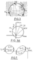
- FIGS. 5A, 5B, 5C illustrate, in the case of a circle trace, the different cases of overflow.
- the circle 30 is, for the most part, located inside the viewing window, that is to say below the window border line Y max .
- the main arc of the circle 30 is therefore drawn inside the window according to the tracing method described above.
- the process of treatment of the protruding parts is activated.
- This treatment process ensures that the projecting part 31 is crushed along the window border, so as to form the straight section 32 (shown in dotted lines), which closes the outline. Arc 31 is not drawn.
- the drawing device detects the crossing of the window border, the overwriting of the overhanging part 42 then consists, in a non-optimized version , to trace not only the junction section 43 ensuring the closing of the contour in cooperation with the circular arc 41 but also two splitting sections 44, 45, located on either side of the closing section 43.
- the splitting of the sections 44, 45 is explained by the fact that, in the corresponding zone (zone 2), for a given abscissa X correspond two points of the arc on the projecting part.
- FIG. 5C presents the configuration in which the circle 60, the major part of which is situated outside the window, projects beyond the level of the window corner 59.
- the method according to the invention makes it possible to avoid tracing the split portions 44, 45, 53, and to eliminate the unnecessary calculation of successive projection of all the points of the arc 54 on the same corner of window 59.
- the projection carried out is therefore optimally limited to the closing sections 51, 52 .
- the curve crossing of the window border is detected and analyzed both when exiting the curve and when entering it inside the window.
- the exit from the window is detected when one of the X or Y coordinates of the curve leaves the interval (x min -x max ); (y min -y max ), respectively (table IV 1.1 ).
- the method consists in determining on which side the concavity of the curve at the current point relative to the window is turned in the case of the circle or the ellipse, that is to say to predict whether the projection of the projecting part will form a split section 44, 45, 53, or not.
- An example of simulation of this test is to be found in table IV 1.2 , the current quadrant being identified by the value of the couple of signs of the partial derivatives of the function at the current point.
- the section "overwrites" is achieved by applying only the increment dx or dy parallel to the window border, which takes the value +1 or -1 depending on the derivative associated with the coordinate in overflow (See tables V 8,9 , 10.11 ).
- the method provides for a "reversal" of the increment, in order to avoid unnecessary tracing . More precisely, unlike the previous case, the increment parallel to the window border will be assigned the opposite value (-1, or +1).
- the tracing device will then directly trace the section 43 following the interior arc 41 (fig. 5B), or the section 51 following the interior arc 55 (fig. 5C), sand unnecessary excursion in 44 and 53 respectively.
- the first condition (increment on the overflow coordinate leading to the window) has the effect of commanding the resumption of the normal tracing process as soon as the overflowing extremum is exceeded, in the case of a minority overflow.
- both of the functions Fx and Fxy will be alternately retained to generate the trace of the current quadrant. It will also be noted that, depending on the resolution of the plotting apparatus and according to the slope of return in the window of the overhanging branch 172, the crushed tracing may be interrupted either slightly before or slightly after crossing point R.
- the second return condition (the current semicircle must cut the window border) makes it possible to take into account the majority overflow condifuration ( Figure 5b). Note that this condition is systematically fulfilled in the case of a minority overflow (Fig.5A and Fig.11).
- the discrimination between the upper half (not referenced) and the lower half 180 of the return branch is carried out using a PLX (overflow in X) or PLY (overflow in Y) flag. ).
- PLX overflow in X
- PLY overflow in Y
- These flags PLX, PLY take only 0 or 1 as a value.
- the value 0 indicates that the current theoretical point is located in the semicircle intercepting the window border.
- the value 1 corresponds to the upper semicircle.
- This mechanism corresponds to the case of drawing arcs of circles or protruding ellipses.
- the PLX, PLY flags also make it possible to optimally process the projection of zone 3 of FIG. 5C (overflow at the corner of the window).
- the process comparators Table IV 1.1
- the PLX PLY flags are simply updated in an order which depends on the concavity with respect to the two crossed limits (x max , y max ) and direction of travel.
- the conditions for the PLX PLY flags to be inverted are that the concavity at the current point is turned towards outside the window, and let the increment on the other direction make it exit the window (Tables VI12, VI13).
- the processing process according to the invention also includes a processing of the stopping criterion in overflow.
- the CAX CAY counters, or their equivalent comparators which serve to control this criterion will therefore be initialized taking into account not the theoretical end point located outside the screen, but its projection on the window border. (Table IIIB 4.7 ). However, this projection is insufficient to discriminate between the two points of the same projection of a zone 2 in overflow. Consequently, the preliminary projection of the end point on the window border is accompanied by the identification of the value of the flags PLX, PLY at the theoretical end point (Table IIIB6).
- FIGS. 6a 6b illustrate two configurations in which the end point 60, 70, of coordinates (x f , y f ) is in overflow, in zones 2 and zones 3 respectively.
- the tracing begins at 61 (initial point x i , y i in overflow).
- the plotted point checks the coordinates of the projection of the end point 60, but the PLX flag has the value 0, and does not coincide with the value of the PLXF flag for the end point.
- the method therefore commands the continuation of the tracing, with tracing of the inscribed arc of a circle 63, turning back in 64, tracing of the crushed section 65, and continuation of the tracing in crushing, beyond the return point 66 of the curve in the window , until reaching the projection 67 of the end point 60.
- the PLX flag of the point current coincides with the PLXF flag previously calculated from the end point. It will be noted that in 66 the cusp condition has not been verified, since the end point 60 is in the zone 2 located beyond the points 66.
- the description of the characteristics of the tracing method of the invention relates specifically to the case where the curve to be traced is a circle or an arc of a circle.
- the method described for the circle can in particular be perfectly generalized in the case of ellipses.
- This variation of the partial derivative results in a change in the properties of the ellipse at its points of intersection with the bounds of the window.
- This variation is taken into account in the calculation of the partial derivatives, but it must also be taken into account in the management of the PLX and PLY flags.
- the process for processing the overhanging parts must therefore include an additional condition for changing the state of the PLX and PLY flags, namely the change of the sign of the partial derivatives f x and f y when moving over the window border.
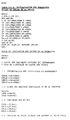
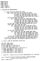
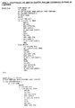
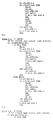
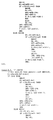
- Tables I to VI annexed to the present application present software for simulating the process of the invention, written in the PASCAL language.
- the method according to the invention is intended to be preferably implemented in the form of wired logic, as shown in FIG. 8.
- the simultation is organized around a main program starting at table IV, a data entry and preliminary processing program (tables IIIA, IIIB, IIIC), as well as two procedures each defining the calculation process of the sign of partial derivatives (table IIA), and the logical expression "OR EXCLUSIVE" (table IIB). These two procedures have been isolated from the main program because they are frequently used during the implementation of the simultaneous tracing method according to the invention.
- the data entry tables comprise on the one hand the initialization process for the circle (table IIIA), and for the right (table IIIC).
- the initialization for the circle consists in determining the quadrant of the starting point, for calculating the partial derivatives (IIIA2, 3), and possibly in projecting the starting point on the window border, when it is overflowing. In the latter case, the corresponding quadrant and initialization calculations of the PLX PLY flags are also ensured (IIIA4, 8).
- the simulation program calculates the value of the partial derivatives (IIIC1), projects, if necessary the initial point in overflow (IIIC2), then calculates the value of the counters CAX, CAY compared to the coordinates of the point final (X f , Y f ) (IIIC3).
- the core of the simultation software consists of a loop ("REPEAT” ... "UNTIL”) which is traversed successively for each point of the curve to be plotted. All the parameters of the curve or portion of the curve have been defined beforehand by reading the content of the display list (IIIA1). The display list is read only once; it is not modified by the implementation of the method of the invention.
- the existence or not of a cusp is a function of four parameters: the direction of the curve, the quadrant of the current point, the sign of the function, the current value of the PLX PLY flags, and the possible existence of an end point in zone 2 or 3.
- Each of the cases corresponding to the different possible combinations for these four parameters is treated in a logical expression (LSAUX, LSAUY) IV2.1.
- the state of the automaton is then determined by taking into account all the useful variables, with switching, for each state of the automaton, to a different subroutine, by means of an addressing table (IV3 ).
- the first eight cases correspond to the different cases determined by the sign of the partial derivatives of the function, the meaning of course, that is to say the different cases of Jordan's algorithm. These eight situations are illustrated in Figure 12, and in the logic table below.
- the input variables SDFY, SDFX, and SENS correspond respectively to the signs of the derivative in y and in x, and to the direction of travel of the circles of FIGS. 12A, 12B.
- the output variables incx incy represent the value of the increments in x and in y, according to the current quadrant (determined by the couple SDFY, SDFX), and the direction of travel. By convention, incx and incy take the value 0 for a positive increment, and the value 1 for a negative increment.
- the entx output variable indicates that it is the incoming function (Fx or Fy) which will be retained according to Bresenham. By convention, the value 0 indicates that the incoming function is: Fy, and the value 1: Fx.
- Figure 13 illustrates cases 8, 9, A and B (tables V 8,9,10 , 11) of the TABRA connection table (INDIC). In this case, it is operating in "blind" mode, cases 8 and 9 corresponding respectively to an increment and a decrement in x on the window border, and cases A and B to a decrement, and to an increment in y.
- Cases C and D are illustrated respectively in FIG. 14A and 14B, and correspond to the crossing of a window corner, with updating of the variables PLY, PLX, respectively (cf. tables V 12, 13 ).
- the case G corresponds to the situation of turning back of the tracks, that is to say of jumps making it possible to avoid the drawing of a crushed split portion.
- the total content of the TABRA table (INDIC) is shown in table B.
- TABRA table can also be replaced by a set of equations, or by any other method of connection.
- the logic of the drawing routine is perfectly independent of the window parameters, which only intervene as variables, which in particular makes it possible to avoid a modification of the display list.
- the method also substantially reduces the durations and the complexity of treatment, compared to the method of preliminary calculation of the points of intersection of the curve with the window, due to the simultaneity of the treatment of the cutting with the drawing process.
- FIG. 8 represents the block diagram of a preferred embodiment of a circuit in wired logic implementing the method according to the invention.
- the command words and the values are sent selectively to registers for storing the coordinates of the end point 102, 103, the coordinates of the calculated initial point 104, 105 (stored in an incrementing decrementing register), and of state of the PLX, PLY flags at the initial and final points, as well as the information of the direction of the trace D (106), and the nature of the curve (108).
- the initialization data of the value of the function at the initial point (FA), as well as of the value of the partial derivatives DFX, DFY, and the value of the parameters of the equation of the curve to be plotted are entered into the transformer 107 ensuring an extension to 32eb so as to allow processing by the Logical Arithmetic Unit 111 of the calculation module 110.
- the module 110 also comprises two RAM memories 112 113 which act as registers for storing the calculation values of the previous iteration and the parameters of the equation. These memories are used to calculate the values of the functions and derivatives for each new point to be plotted.
- the circuits 132 and 133 are supplied respectively by the incrementing decrementing register x 105 and the register 103 for storing the abscissa xf of the end point for the circuit 132, and by the equivalent registers Y 104 and 102 for the circuit 133.
- the module 140 detects the overflow of the curve, by means of comparator circuits 141, 142 working on the one hand on the parameters of the display window stored in the registers 143, 144, 145, 146 and on the other hand on the value coordinates of the current point from registers 105, 104, (Table IV 1.1 ).
- the set of logic variables provided by the module 130 of the stopping criteria, the overflow detection module 140, and the register 106, is supplied to the logic module 120 for determining the change of state of the automaton.
- This logic module determines the state of the PLC (Table IV3 of the simulation software) according to the logic variables BXMIN, BXMAX, BYMIN, BYMAX, D, XFMX, YFMY, and the current values of the PLX, PLY flags determined iteratively from their value at the initial point PLXI, PLYI as well as values from the circuit 115 SDFX, SDFY, SFA (Table IV 2.3 ).
- the module then supplies the state information of the automaton (case 0 to case G) to the sequencing module 121.
- the latter deduces therefrom the values of the increments dx, dy to be supplied to the incrementing-decrementing registers 105, 104 .
- the module 121 also ensures, as already mentioned, the sequencing of the circuits 111, 112, 113 and of the transformer circuit 107 and more generally of the assembly.
- the increments dx, dy supplied to the register 104 105 make it possible to obtain the coordinates (x, y) of the new plotted point (150), which are supplied to the plotting module of the graphic and videographic plotting apparatus, or the like. These same values are reintroduced into modules 130, 140 for the calculations of the new iteration.
- the dx / dy increments can also be output at 150.
- the parameters of the window are supplied to the plot processor, independently of the content of the display list, and without feedback on it. This makes it possible in particular to structure the various processors linked to a graphic display system into a pipe line.
- the method according to the invention is particularly suitable for optimizing the filling of overflowing closed surfaces.
- the filling operation is generally carried out by re-reading the contours, these having been stored with management of the parity of the number of points on each line or each column according to the scanning direction for filling.
- the number of points saved thanks to the process is calculated differently, for example in the case of the drawing of an overflowing circle, for each of the quadrants delimited by the lines 80, 81 oriented at 45 ° and 135 ° (FIG 10A). These lines indeed delimit the zones for which the slopes in Y are lower (or higher respectively) than the slopes in X.
- the method of tracing overflowing curves according to the invention therefore not only ensures a reduction in the storage capacities required (due to the "blind” operation), but also allows an acceleration of the processing time due to the reduction in the number calculated points.
Landscapes
- Physics & Mathematics (AREA)
- Engineering & Computer Science (AREA)
- Geometry (AREA)
- Computer Graphics (AREA)
- General Physics & Mathematics (AREA)
- Theoretical Computer Science (AREA)
- Image Generation (AREA)
Claims (14)
- Verfahren zum Aufzeichnen einer Kurve im Inneren eines Displayfensters eines Graphikaufzeichnungsgerätes, wobei das Displayfenster durch Ränder begrenzt ist, die Kurve durch kontinuierliche Verkettung von einfachen geometrischen Kurventeilen erster und/oder zweiter Ordnung gebildet wird und ein Teil der Kurve außerhalb des Displayfensters verläuft, mit den Verfahrensschritten:a) Man definiert in einer Displayliste jeden geometrischen Kurventeil durch:. die Koordinaten von charakteristischen Punkten (Anfangspunkt, Endpunkt) des geometrischen Kurventeils,. die Parameter der Funktion, die den geometrischen Kurventeil darstellt,. die Art des geometrischen Kurventeils (Gerade, Kreis, Ellipse),. die Laufrichtung für einen geometrischen Kurventeil zweiter Ordnung;b) man definiert u.a. in der Displayliste die Ränder des Displayfensters durch Randparameter;c) man bestimmt, ausgehend von einem aktuellen Bahnpunkt, die Inkremete (dx,dy), um einen neuen aktuellen Bahnpunkt zu erhalten durch Kombination der Koordinaten des aktuellen Punktes mit den bestimmten Inkrementen,d) man wiederholt Schritt c) bis der aktuelle Bahnpunkt mit dem Endpunkt des geometrischen Kurventeils zusammenfällt;gekennzeichnet durch die Schritte:e) Man initialisiert vor dem Schritt c) der Bestimmung der Inkremente eine Vielzahl von Verarbeitungskriterien ausgehend von der Berechnung der partiellen Ableitungen der Funktion im aktuellen Punkt, vom Vergleich der Koordinaten des aktuellen Punktes mit den Randparametern und von der Messung der Abweichung zwischen aktuellem Punkt und Endpunkt;f) man aktualisiert während des Schrittes c) die Verarbeitungskriterien als Funktion des neuen aktuellen Punktes und man bestimmt, ausgehend von diesen Verarbeitungskriterien, eine Information bezüglich einer speziellen Verarbeitung, die unter mehreren Verarbeitungen aktiviert werden soll, wobei jede Verarbeitung für sich genommen die speziellen Inkremente bestimmt und die möglichen Verarbeitungen mindestens eine Verarbeitung für jeden geometrischen Kurventeil, der im Displayfenster enthalten ist, um die Inkremente (dx,dy) zu erzeugen, die die den geometrischen Kurventeil darstellende Funktion minimieren, und eine Verarbeitung für den Teil des geometrischen Kurventeils einschließen, der nach außerhalb des Displayfensters übergreift, welche die Schritte aufweist:g) Für einen geometrischen Kurventeil, der nach außerhalb des Displayfensters übergreift: Bestimmung des überschrittenen Fensterrandes und der Koordinate des aktuellen Punktes beim Übergriff, oder für einen geometrischen Kurventeil der einen Anfangspunkt außerhalb des Fensters hat: Bestimmung eines aktuellen Startpunktes der Bahn durch Projektion des Anfangspunktes auf den Fensterrand,h) Bestimmung der Position (XFMX,YFMY) des aktuellen Punktes im Verhältnis zu dem Endpunkt;i) Erzeugung eines Inkrementes (dx oder dy) parallel zum Fensterrand, um eine Stauchungsbahn des übergreifenden geometrischen Kurventeils längs des überschrittenen Fensterrandes zu realisieren, wobei das Vorzeichen des Inkrementes bestimmt wird als Funktion der Position (XFMX,YFMY) und einer Identifikation (PLX,PLY) der Konkavität der Funktion für die übergreifende Koordinate.
- Verfahren nach Anspruch 1, wobei der Verfahrensschritt e) der Initialisierung die folgenden Schritte aufweist:- Bestimmung des Startquadranten durch Berechnung der partiellen Ableitungen der Funktion im Anfangspunkt;- Projektion des Anfangspunktes auf einen Rand des Displayfensters, wenn der Startpunkt außerhalb liegt;- Projektion des Endpunktes auf einen Rand des Displayfensters, wenn der Endpunkt außerhalb liegt;- Messung der Abweichung zwischen Anfangspunkt und Endpunkt.
- Verfahren nach Anspruch 2, wobei die spezielle Verarbeitung für den Teil des geometrischen Kurventeils im Inneren des Displayfensters besteht aus: Bestimmen der Inkremente (dx,dy) ausgehend von drei möglichen Inkrementationskonfigurationen, dann Auswählen des neuen aktuellen Punktes, der am nächsten der Kurve liegt aus den drei möglichen Konfigurationen mittels des Jordan-Verfahrens, danach automatische Eliminierung einer der Inkrementationskonfigurationen mit Hilfe des Bresenham-Verfahrens ergänzt durch die Berücksichtigung der Laufrichtung des geometrischen Kurventeils (für einen geometrischen Kurventeil zweiter Ordnung) und des Vorzeichens der partiellen Ableitungen im aktuellen Punkt (Quadrant).
- Verfahren nach Anspruch 3, bei welchem die Verarbeitungskriterien u.a. beinhalten: Die Benutzung von Marken (PLX,PLY), die die Konkavität des geometrischen Kurventeils repräsentieren mit Bezug auf die Ränder des Displayfensters, wobei der Wert der Marken berechnet wird ausgehend vom Vorzeichen der partiellen Ableitungen im aktuellen Punkt.
- Verfahren nach Anspruch 4, wobei die Verarbeitungskriterien u.a. ein Anhaltekriterium der Bahn enthalten, ein Umkehrkriterium des geometrischen Kurventeils und ein Kriterium der Wiederaufnahme der Bahn im Inneren des Displayfensters.
- Verfahren nach Anspruch 5, wobei das Anhaltekriterium der Bahn verifiziert wird durch die Koinzidenz der Parameter des aktuellen Punktes (X,Y,PLX,PLY) mit den Parametern des projizierten Endpunktes (Xf,Yf,PLXf,PLYf).
- Verfahren nach Anspruch 5, wobei das Umkehrkriterium des geometrischen Kurventeils verifiziert wird in Funktion der Orientierung der Konkavität des geometrischen Kurventeils am Rand des Fensters, der äußeren oder inneren Position des aktuellen Punktes bezüglich dem geometrischen Kurventeil, des Übergreifens des aktuellen Punktes und der Relativposition des aktuellen Punktes und des Endpunktes.
- Verfahren nach Anspruch 5, wobei das Wiederaufnahmekriterium im Inneren des Fensters verifiziert wird durch die Bahn eines Kreis- oder Ellipsenbogens, wenn:- das aktuelle Inkrement, welches der übergreifenden Koordinate entspricht, die Bahn in Richtung auf das Fenster leitet;- die projizierte aktuelle Bahn einem Halbkreis (Halbellipse) entspricht, die den Rand des Fensters schneidet, und der Endpunkt nicht jenseits des Randes liegt.
- Verfahren nach Anspruch 5, wobei die spezielle Verarbeitung eines geometrischen Kurventeils im Übergriff an einer Ecke des Fensters sich darauf beschränkt, den Wert der Marken (PLX,PLY) nach der Bahn eines Einheitspunktes in der Ecke des Fensters unmittelbar zu aktualisieren.
- Verfahren nach Anspruch 9, wobei das Vorzeichen des Inkrementes für die Stauchungsbahn eine Funktion des Wertes der Marke (PLX,PLY) ist, wobei das automatische Inkrement (dx oder dy) das gleiche Vorzeichen hat wie das entsprechende Inkrement für den aktuellen Quadranten, wenn die Konkavität des geometrischen Kurventeiles auf das Innere des Fensters gerichtet ist auf der Höhe des Randes des Fensters (PLX und/oder PLY = 0), und das entgegengesetzte Vorzeichen zum entsprechenden Inkrement, wenn die Konkavität der Kurve auf das äußere des Fensters gerichtet ist beim Schneiden mit dem Rand des Fensters (PLX und/oder PLY = 1).
- Verfahren nach Anspruch 1, wobei der Wert der Funktion im Anfangspunkt der Bahn so initialisiert ist, daß der Wert der Funktion im theoretischen Endpunkt des Displays 0 ist, um zu erlauben, daß ein Anhalten der Bahn eines geometrischen Kurventeils detektiert wird durch perfekte Koinzidenz des theoretischen Endpunktes mit einem Bahnpunkt.
- Verfahren nach Anspruch 4, wobei die Überprüfung der Koinzidenz des theoretischen Endpunktes mit einem Bahnpunkt zum Feststellen des Anhaltens der Bahn eines geometrischen Kurventeils bewirkt wird, durch die Koordinaten (X,Y) des Bahnpunktes und den Wert der Marken (PLX,PLY).
- Schaltung zum Durchführen des Aufzeichnens einer Kurve im Inneren eines Displayfensters eines geometrischen Aufzeichnungsgerätes, wobei das Displayfenster durch Ränder begrenzt ist, die Kurve durch kontinuierliche Verbindung von einfachen geometrischen Kurventeilen erster und/oder zweiter Ordnung gebildet wird und ein Teil der Kurve außerhalb des Displayfensters verläuft, wobei die Schaltung realisiert ist in der Form einer verdrahteten Logik und am Eingang (100) den Inhalt einer Displayliste empfängt, die jeden geometrischen Kurventeil definiert durch: Die Koordinaten von charakteristischen Punkten (Anfangspunkt, Endpunkt) des Kurventeils, die Parameter der Funktion, die den geometrischen Kurventeil darstellt, die Art des geometrischen Kurventeils (Gerade, Kreis, Ellipse), die Laufrichtung für einen geometrischen Kurventeil zweiter Ordnung; und u.a. die Ränder des Displayfensters durch Randparameter definiert, wobei die Schaltung am Ausgang (150) die Koordinaten (x,y) und/oder die Inkremente (dx,dy) (-1, 0, 1) jedes aktuellen aufzuzeichnenden Punktes liefert, wobei die Inkremente (dx,dy) es erlauben, einen neuen aktuellen Kurvenpunkt der Bahn zu erhalten, durch Kombination der Koordinaten des vorangehenden aktuellen Punktes mit den bestimmten Inkrementen, und wobei die Berechnung der Inkremente wiederholt wird bis der aktuelle Bahnpunkt mit dem Endpunkt des geometrischen Kurventeils zusammenfällt, wobei die logische Schaltung gekennzeichnet ist durch:
Initialisierungsmittel für eine Vielzahl von Verarbeitungskriterien, ausgehend von der Berechnung der partiellen Ableitungen der Funktion im aktuellen Punkt, dem Vergleich der Koordinaten des aktuellen Punktes mit den Randparameter und dem Messen der Abweichung zwischen aktuellem Punkt und Endpunkt,
Aktualisierungsmittel für die Verarbeitungskriterien als Funktion des neuen aktuellen Punktes und Bestimmungsmittel für eine Information bezüglich einer speziellen Verarbeitung ausgehend von diesen Verarbeitungskriterien, die unter mehreren möglichen Verarbeitungen aktiviert werden soll, und durch Verarbeitungsmittel, die ein logisches Modul (120) enthalten zur logischen Bestimmung des Wertes der Inkremente in Abhängigkeit vom Zustand der folgenden logischen Variablen: Variable (BXMIN,BXMAX,BYMIN,BYMAX) der Position des aktuellen Punktes bezüglich des Fensters; Variable (D) der Information über die Richtung der Kurvenbahn; Identifikationsmarken der Halbellipse oder des Halbkreises (PLX,PLY) der aktuellen projizierten Bahn, Variable (XFMY,YFMY) der Positionierung des aktuellen Punktes bezüglich dem Endpunkt, des Vorzeichens der Funktion, des Vorzeichens der partiellen Ableitungen, des Vergleichs des Wertes der Funktion, die zwei Inkrementationsrichtungen entspricht, wobei jede Verarbeitung für sich genommen die speziellen Inkremente bestimmt und die möglichen Verarbeitungen mindestens eine Verarbeitung für jeden geometrischen Kurventeil der im Displayfenster enthalten ist, um die Inkremente (dx,dy) zu erzeugen, die die den geometrischen Kurventeil darstellende Funktion minimieren, und eine Verarbeitung für den Teil des geometrischen Kurventeils einschließen, der nach außerhalb des Displayfensters übergreift, um zu bestimmen: Für einen geometrischen Kurventeil, der nach außerhalb des Displayfensters übergreift:
Des überschrittenen Fensterrandes und der Koordinate des aktuellen Punktes beim Übergriff, oder für einen geometrischen Kurventeil, der einen Anfangspunkt außerhalb des Fensters hat: Eines aktuellen Startpunktes der Bahn durch Projektion des Anfangspunktes auf den Fensterrand, um die Positionsvariable (XFMX,YFMY) des aktuellen Punktes im Verhältnis zum Endpunkt zu bestimmen und ein Inkrement (dx oder dy) parallel zum Fensterrand zu erzeugen, um eine Stauchungsbahn des übergreifenden geometrischen Kurventeils längs des überschrittenen Fensterrandes zu realisieren, wobei das Vorzeichen des Inkrementes bestimmt wird als Funktion der Position (XFMX,YFMY) und einer Identifikation (PLX,PLY) der Konkavität der Funktion für die übergreifende Koordinate. - Schaltung nach Anspruch 13, dadurch gekennzeichnet, daß sie besteht aus einem Modul (110) für die iterative Berechnung des Wertes (Fa;DFX,DFY), der durch die algebraische Gleichung des aufzuzeichnenden Kurventeils gegeben ist, und durch die partiellen Ableitungen im aktuellen Punkt; ein Modul (130) zur Bestimmung der Relativposition des aktuellen Punktes bezüglich des Endpunktes; ein Modul (140) zur Bestimmung der Relativposition des aktuellen Punktes bezüglich des Darstellungsfensters, und Registern zum Inkrementieren-Dekrementieren (104,105), die die Koordinaten (x,y) des neuen aktuellen Punktes liefern, ausgehend von den Werten der Inkremente (dx,dy), die durch das logische Modul (120) in Zusammenarbeit mit einem logischen und sequentiellen Modul (121) geliefert werden.
Applications Claiming Priority (2)
| Application Number | Priority Date | Filing Date | Title |
|---|---|---|---|
| FR8706796 | 1987-05-14 | ||
| FR8706796A FR2615301B1 (fr) | 1987-05-14 | 1987-05-14 | Procede de tracage de courbes debordantes a l'interieur d'une fenetre de visualisation, et circuits de mise en oeuvre d'un tel procede |
Publications (2)
| Publication Number | Publication Date |
|---|---|
| EP0293283A1 EP0293283A1 (de) | 1988-11-30 |
| EP0293283B1 true EP0293283B1 (de) | 1993-12-15 |
Family
ID=9351104
Family Applications (1)
| Application Number | Title | Priority Date | Filing Date |
|---|---|---|---|
| EP19880401167 Expired - Lifetime EP0293283B1 (de) | 1987-05-14 | 1988-05-11 | Verfahren zum Trassieren über das Innere eines Sichtfensters hinausragender Kurven und Schaltungen zum Durchführen |
Country Status (3)
| Country | Link |
|---|---|
| EP (1) | EP0293283B1 (de) |
| DE (1) | DE3886263D1 (de) |
| FR (1) | FR2615301B1 (de) |
Family Cites Families (2)
| Publication number | Priority date | Publication date | Assignee | Title |
|---|---|---|---|---|
| JPS60220473A (ja) * | 1984-04-17 | 1985-11-05 | Fujitsu Ltd | シザリング方式 |
| KR930005777B1 (ko) * | 1984-05-02 | 1993-06-24 | 가부시기가이샤 히다찌세이사꾸쇼 | 도형 처리장치 |
-
1987
- 1987-05-14 FR FR8706796A patent/FR2615301B1/fr not_active Expired
-
1988
- 1988-05-11 EP EP19880401167 patent/EP0293283B1/de not_active Expired - Lifetime
- 1988-05-11 DE DE88401167T patent/DE3886263D1/de not_active Expired - Lifetime
Also Published As
| Publication number | Publication date |
|---|---|
| FR2615301A1 (fr) | 1988-11-18 |
| EP0293283A1 (de) | 1988-11-30 |
| FR2615301B1 (fr) | 1989-08-18 |
| DE3886263D1 (de) | 1994-01-27 |
Similar Documents
| Publication | Publication Date | Title |
|---|---|---|
| CN111476759B (zh) | 一种屏幕表面检测方法、装置、终端及存储介质 | |
| KR102170620B1 (ko) | 지역적 특징을 가지는 분류기 학습을 위한 학습 데이터 생성 방법 및 그 시스템 | |
| KR102628115B1 (ko) | 영상 처리 방법, 장치, 기록 매체 및 전자 장치 | |
| CN117392042A (zh) | 缺陷检测方法、缺陷检测设备及存储介质 | |
| GB2608783A (en) | Integrated interactive image segmentation | |
| CN117132583A (zh) | 晶圆缺陷检测方法、装置、电子设备及非易失性存储介质 | |
| JP6102122B2 (ja) | 画像処理装置および方法、並びにプログラム | |
| US12198288B2 (en) | Systems and methods for generating an image of an automobile | |
| US20250209796A1 (en) | Generating annotated data samples for training using trained generative model | |
| EP0354833B1 (de) | Verfahren zur Beseitigung der bedeckten Flächen für die Synthese eines dreidimensionalen fadenförmigen Bildes | |
| WO2024067144A1 (zh) | 图像处理方法、装置、设备、计算机可读存储介质及产品 | |
| CN114140812A (zh) | 一种图元识别方法、装置、设备及介质 | |
| CN120451035A (zh) | 使用自监督缺陷生成器从视觉检查数据集生成少数类别缺陷检测数据 | |
| CN120635410A (zh) | 基于缺陷检测的样本生成方法、设备及存储介质 | |
| Kar | Mastering Computer Vision with TensorFlow 2. x: Build advanced computer vision applications using machine learning and deep learning techniques | |
| CN110879972A (zh) | 一种人脸检测方法及装置 | |
| US12555214B2 (en) | Obtaining realistic boundaries of structural defects of materials in images of structures | |
| CN113272857A (zh) | 缺陷图像生成装置及方法 | |
| CN116051366A (zh) | 一种图像处理方法、装置、设备及存储介质 | |
| CN120766249A (zh) | 一种大模型在自动驾驶中的环境感知与决策方法及系统 | |
| EP0293283A1 (de) | Verfahren zum Trassieren über das Innere eines Sichtfensters hinausragender Kurven und Schaltungen zum Durchführen | |
| US5231696A (en) | Process and circuitry for implementing plotting of overextending curves inside a display window | |
| CN117830162A (zh) | 图像修复方法、装置、设备及存储介质 | |
| CN118351059A (zh) | 电路板检测方法、装置、计算机设备和存储介质 | |
| CN114612537B (zh) | 数字孪生图像与真实图像配准方法、设备及可读存储介质 |
Legal Events
| Date | Code | Title | Description |
|---|---|---|---|
| PUAI | Public reference made under article 153(3) epc to a published international application that has entered the european phase |
Free format text: ORIGINAL CODE: 0009012 |
|
| AK | Designated contracting states |
Kind code of ref document: A1 Designated state(s): DE GB NL |
|
| 17P | Request for examination filed |
Effective date: 19890130 |
|
| 17Q | First examination report despatched |
Effective date: 19900924 |
|
| RAP1 | Party data changed (applicant data changed or rights of an application transferred) |
Owner name: TELEDIFFUSION DE FRANCE Owner name: FRANCE TELECOM |
|
| GRAA | (expected) grant |
Free format text: ORIGINAL CODE: 0009210 |
|
| AK | Designated contracting states |
Kind code of ref document: B1 Designated state(s): DE GB NL |
|
| PG25 | Lapsed in a contracting state [announced via postgrant information from national office to epo] |
Ref country code: NL Effective date: 19931215 Ref country code: DE Effective date: 19931215 |
|
| REF | Corresponds to: |
Ref document number: 3886263 Country of ref document: DE Date of ref document: 19940127 |
|
| GBT | Gb: translation of ep patent filed (gb section 77(6)(a)/1977) |
Effective date: 19940310 |
|
| REG | Reference to a national code |
Ref country code: GB Ref legal event code: 746 Effective date: 19940325 |
|
| NLV1 | Nl: lapsed or annulled due to failure to fulfill the requirements of art. 29p and 29m of the patents act | ||
| PLBE | No opposition filed within time limit |
Free format text: ORIGINAL CODE: 0009261 |
|
| STAA | Information on the status of an ep patent application or granted ep patent |
Free format text: STATUS: NO OPPOSITION FILED WITHIN TIME LIMIT |
|
| 26N | No opposition filed | ||
| REG | Reference to a national code |
Ref country code: GB Ref legal event code: IF02 |
|
| PGFP | Annual fee paid to national office [announced via postgrant information from national office to epo] |
Ref country code: GB Payment date: 20040428 Year of fee payment: 17 |
|
| PG25 | Lapsed in a contracting state [announced via postgrant information from national office to epo] |
Ref country code: GB Free format text: LAPSE BECAUSE OF NON-PAYMENT OF DUE FEES Effective date: 20050511 |
|
| GBPC | Gb: european patent ceased through non-payment of renewal fee |
Effective date: 20050511 |