EP0293243A2 - Printer - Google Patents
Printer Download PDFInfo
- Publication number
- EP0293243A2 EP0293243A2 EP88304857A EP88304857A EP0293243A2 EP 0293243 A2 EP0293243 A2 EP 0293243A2 EP 88304857 A EP88304857 A EP 88304857A EP 88304857 A EP88304857 A EP 88304857A EP 0293243 A2 EP0293243 A2 EP 0293243A2
- Authority
- EP
- European Patent Office
- Prior art keywords
- platen
- paper
- sheet
- printer
- frame
- Prior art date
- Legal status (The legal status is an assumption and is not a legal conclusion. Google has not performed a legal analysis and makes no representation as to the accuracy of the status listed.)
- Granted
Links
Images


Classifications
-
- B—PERFORMING OPERATIONS; TRANSPORTING
- B41—PRINTING; LINING MACHINES; TYPEWRITERS; STAMPS
- B41J—TYPEWRITERS; SELECTIVE PRINTING MECHANISMS, i.e. MECHANISMS PRINTING OTHERWISE THAN FROM A FORME; CORRECTION OF TYPOGRAPHICAL ERRORS
- B41J11/00—Devices or arrangements of selective printing mechanisms, e.g. ink-jet printers or thermal printers, for supporting or handling copy material in sheet or web form
- B41J11/48—Apparatus for condensed record, tally strip, or like work using two or more papers, or sets of papers, e.g. devices for switching over from handling of copy material in sheet form to handling of copy material in continuous form and vice versa or point-of-sale printers comprising means for printing on continuous copy material, e.g. journal for tills, and on single sheets, e.g. cheques or receipts
-
- B—PERFORMING OPERATIONS; TRANSPORTING
- B41—PRINTING; LINING MACHINES; TYPEWRITERS; STAMPS
- B41J—TYPEWRITERS; SELECTIVE PRINTING MECHANISMS, i.e. MECHANISMS PRINTING OTHERWISE THAN FROM A FORME; CORRECTION OF TYPOGRAPHICAL ERRORS
- B41J13/00—Devices or arrangements of selective printing mechanisms, e.g. ink-jet printers or thermal printers, specially adapted for supporting or handling copy material in short lengths, e.g. sheets
- B41J13/10—Sheet holders, retainers, movable guides, or stationary guides
- B41J13/103—Sheet holders, retainers, movable guides, or stationary guides for the sheet feeding section
Definitions
- This invention relates to the field of printing and more particularly to a simplified mechanism for positioning and moving paper through a serial character printer.
- this mechanism is capable of accepting continuous forms and hand and paper tray fed cut sheets of paper alternatively without having to unload and reload the printer.
- Printers may be classified by the rate and technique used to print on the paper. Of particular interest due to their low cost to both acquire and operate are serial character printers. These printers typically print a single character at a time using an impact, usually a dot matrix impact, ink jet or thermal technique.
- printers have two key subsystems, the paper feed subsystem and the printing mechanism.
- the essential aspect of such printers being their low cost, attention must be paid to the cost of each subsystem.
- a printer for printing on individually or continuously fed sheets comprising a frame, a platen mounted on the frame, sheet guides attached to the frame, a sheet sensor attached to the frame, a carriage having a print head, carriage drive means for movably mounting the carriage in the printer and moving the print head parallel to the platen from a starting to an ending print position, and platen drive means mounted on the frame and coupled to the platen for advancing a fed sheet around the platen, characterised in that there are also provided one or more further printer component means with respective printer component operating means, and control means for controlling the carriage drive means, the printer component operating means and the platen drive means, the control means being responsive to the sheet sensor.
- An advantage of the invention is that it provides a low cost and very reliable paper feed system. Furthermore it accepts and reliably handles a variety of paper, including cut sheets and continuous forms, without adding solenoids or expensive motors.
- the cut sheets may be hand- or automatically fed. Moreover it permits the type of paper being used in the printer to be changed without the user having to unload the current paper and load the new type of paper.
- a single paper sensor is employed for detecting paper fed from any paper path.
- a sheet sensor for a printer for detecting the presence of a sheet fed from a first or second sheet path comprising frame in 5 close proximity to both sheet paths an arm mounted on the frame and having a first and second portions, the arm being pivotally mounted about a point located between the first and second portions, with the first portion being in the first path and the second portion being in the second sheet path, and an optical detector mounted on the frame and being responsive to the arm.
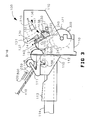
- FIG 1 is a top view of the preferred embodiment of the present invention.
- FIG 2 is a side view of the preferred embodiment of the present invention.
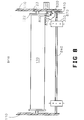
- FIG 8 is a front view of the preferred embodiment of the present invention.
- the printer 100 comprises a frame 110, a platen assembly, a carriage assembly, a continuous form feeder assembly, an optional cut sheet feeder assembly and a printer controller.
- the paper feed path is selected by the user through a printer control panel or the user's computer system through a communications interface.
- the printer frame 110 and indeed most of the printer parts, are made from injection molded plastic.
- the platen assembly accepts paper from one of three paper feed paths and precisely positions the paper to permit the carriage assembly to print on the paper.
- This printer accepts single cut sheets of paper fed from a paper tray, single cut sheets of paper feed by hand, and continuous forms.
- the carriage assembly which mounts in frame 110 holds and positions the print head used to print the characters on the paper. Any type of print head, thermal, impact, or ink jet may be used with the present invention. In the preferred embodiment of the present invention, a dot matrix impact type print head having 24 print wires is employed.
- the carriage assembly also serves to select the paper path which will be used to feed paper into the platen assembly and to control the bail and other parts of the printer. By using the carriage to control the operation of the platen assembly, solenoids and expensive motors have been eliminated thereby reducing the cost and improving the reliability of the printer.
- the continuous form feeder assembly accepts and holds continuous forms and transfers those forms to the platen assembly when the user or the user's computer system selects continuous forms.
- the cut sheet feeder assembly accepts and holds cut sheets of paper in a paper tray and transfers one sheet of paper at a time to the platen when the tray feed is selected.
- the platen assembly comprises the platen 120, a bail 140, pinch rollers 600 and paper guides 112 and 220.
- the platen is made of hard rubber.
- the platen 120 has a gear 121 and 122 located at both ends of the platen 120.
- Two ribbed spacers 123 are molded with gears 121 and 122.
- the spacers 123 are used to center the platen 120 in frame 110.
- the platen is mounted in a manner which permits it to rotate freely.
- the platen is rotated by the platen motor 125 through a gear hub 800.
- Pinch rollers 600 are employed to guide the paper around the platen.
- Two paper guides 112 and 220 are also employed to guide the paper. Both paper guides are made of steel.
- the paper guide 112 is used to guide single sheets, either fed from a paper tray or by hand, around the bottom of the platen. Continuous forms are directed up from the bottom of the printer as described below.
- the paper guide 220 holds paper against the platen as the paper approaches the print head 130.
- a third paper guide 230, attached to the carriage assembly insures that the paper will not catch on the bottom of the print head and jam The paper then passes under a bail 140.
- the bail 140 is made of steel and has rollers 141 which permit the paper to move smoothly between the bail and the platen 120.
- the bail is mounted in the frame 110 and has a first and second position.
- the bail 140 is biased into the first position by a spring 240. In the first position the bail is resting against the platen 120.
- the bail 140 keeps the paper flat against the platen 120 while the printer is printing.
- In the second position the bail 140 is held away from the platen by a distance which permits paper to be load into the printer. This distance must be sufficient to insure that the paper always passes between the bail 140 and the platen 120.
- the bail is bent at point 146 to prevent the bail from hitting the print head when the print head is in the home position and the bail is in the second position.
- the carriage assembly comprises the print head 130, a carriage 131, carriage guides 132 and 137, and a carriage drive subsystem.
- the print head is firmly mounted to the carriage 131.
- the carriage mounts on the carriage guides 132 and 137 which are attached to the frame 110.
- the carriage moves parallel to the platen 120 on the steel guides 132 and 137.
- the carriage 131 has two novel actuators 139 and 128.
- Actuator 139 has a flat tip and an angled section 145. The angled section is at approximately 33 degrees from the flat tip.
- the actuator 128 has a flat tip and a smooth top. The operation of the actuators will be described below.
- the carriage drive subsystem comprises a motor 135, hubs 134 and 136 and a belt 133.
- the belt is driven by a hub 134 attached to the motor 135.
- the other end of the belt is supported by hub 136 and kept under tension by a wedge and spring mechanism 210.
- the continuous form feeder assembly comprises two sprockets 320, drive shaft 840, drive gear 810 and a clutch assembly.
- the sprockets 320 have covers, not shown, which hold the continuous forms against the sprockets 320.
- the sprockets are mounted on the square drive shaft 840 which may be driven through a sprocket drive gear 810.
- the sprocket drive gear 810 has a first and second position. In first position the continuous form assembly is driven by the platen motor 125 through hub 800. In the second position the continuous form assembly is disengaged from the platen motor 125.
- the drive gear 810 is biased into the second position by a spring 870 The drive gear 810 is moved from the second position to the first position by the clutch assembly.
- the clutch assembly comprises a clutch arm 820 and a spring 860.
- One end of the clutch arm 820 has a Y shape which contacts drive gear 810.
- the other end of the clutch arm 820 rests in slot 830 of the frame 110 and is held in the slot by the spring 860.
- the spring is shown in FIG 9A.
- a cut sheet feeder assembly comprises subframe 111, a cut sheet paper tray 114, idler gear 158, a sheet feeder, and an output feeder.
- the subframe attaches to the frame 110.
- the idler gear 158 is rotatably mounted to the subframe 111.
- the paper try 114 mounts in a printer tray support 113 molded into the frame 110.
- the sheet feeder comprises a drive rod 151 which is mounted in a bearing in subframe 111, two wheels 154 and a clutch assembly.
- the clutch assembly comprise a gear 156, a spring 155 and a clutch arm 150.
- the drive rod 151 is driven by gear 156 which is held against the subframe 111 by spring 155.
- the gear 156 is driven by the platen drive motor 125 through gear 158 and the platen gear 121.
- Two D shaped rubber wheels 154 are mounted to the drive rod 151. The rubber wheels are positioned so that they make contact with the top sheet of paper in the paper feeder tray 114.
- a clutch arm 150 having a Y shaped end rests against the gear 156 and passes through a hole in the frame 110. The clutch arm is mounted on a pivot which is attached to the subframe 111.
- the output feeder comprises a drive rod 152 which is mounted in a bearing in subframe 111.
- the drive rod 152 is driven by gear 159 through gear 158 and platen gear 121 from the platen drive motor 125.
- Two rubber wheels 153 are mounted to the drive rod 152 and assist the paper as it moves off the platen 120 into an output tray which is a shelf in the case of the printer.
- the cut sheet feeder is optional and may be removed by disconnecting subframe 111 from frame 110 and removing the paper tray 114. This permits even a further reduction in cost if desired.
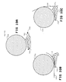
- FIG 10A, FIG 10B and FIG 10C describe a paper sensor employed in the preferred embodiment of the present invention.
- the paper sensor 700 comprises a detector arm 701 pivotally mounted below the platen 120 in a slot in the structural frame member 240.
- the arm 701 swings freely and, at the end of its travel, breaks a light beam in optical detector 702.
- the paper sensor is capable of detecting either cut sheets of paper fed from the back of the printer, or continuous forms fed from underneath the printer.
- FIG 10A illustrates the paper sensor 700 without any paper present.
- the arm 701 swings down beneath the light beam of the optical detector 702. In this position, the arm 701 comes into close proximity, but does not touch, the platen 120.
- FIG 10B illustrates the paper sensor 700 with a cut sheet of paper 500 present.
- FIG 10C illustrates the paper sensor 700 with continuous forms.
- the continuous forms 500 are fed from the bottom of the printer through the sprockets 310 and up toward the platen 120. As the paper passes point 711 on the arm 701, the arm is pushed down and breaks the light beam in the optical detector. In this manner, one paper sensor is capable of detecting paper coming from any paper path.
- the printer operates as follows, depending on the type of paper selected.
- the preferred embodiment of the present invention accepts cut sheets of paper fed either by hand or from a paper tray and continuous forms alternately under the control of the printer controller as selected by the user or the user's computer system.
- FIG 3 is a side view of the present invention having a single cut sheet of paper loaded by hand.
- a single sheet of paper may be loaded by placing the sheet of paper through a slot of the printer case (not shown) between an alignment tray 410 and the output tray 420 until it strikes the platen 120. The user then presses a line feed switch on the printer control panel which causes the platen to begin to rotate. The sheet of paper then trips the paper sensor. Once the paper 500 is detected, the printer automatically loads the sheet of paper. The first step in loading the paper is to position the paper around the platen 120.
- the printer controller continues rotating the platen and thereby feeding the paper between the platen 120 and the frame member 240, underneath guide 220 and around to immediately in front of the print head 130.
- the top printable line of the paper approximately one-sixth of an inch below the top of the paper, is aligned beneath the print head 130 and the printer begins printing.
- the exact position of the paper is determined by the printer controller from when the paper passed the paper sensor and the number of revolutions of the platen drive motor 125. Depending on the size and spacing of the printer font selected, the printer will be able to print approximately four lines before the top of the paper runs up against the bail 140.
- the next step is to lift the bail.
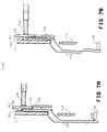
- FIG 4A and FIG 4B illustrate the operation of the bail lift mechanism.
- FIG. 4A shows the actuator 139 located on the carriage 131 with the carriage 131 in the home position. In this position, the print head 130 is aligned with the first printable column on the paper. This position is referred to as the home position.
- the carriage motor moves the carriage 131 past the home thereby driving the wedge portion against the side of bail 140 and forcing the bail away from the platen 120. This does not affect the printing operation of the printer since the printer will not need to print left of the first printable column on the paper.
- FIG 4B illustrates the lifted bail 140.
- the bail lift procedure is as follows: the printer backs the paper down approximately four lines, lifts the bail as described above, and advances the paper approximately five lines. The bail is then released by moving the carriage 131 back to the home position thereby moving the actuator 139 away from the bail and allowing the spring 240 to move the bail back against the platen 120.
- the printer then continues to print on the paper until the last printable line of the printer is reached.
- the last printable line is defined to be approximately one-quarter inch from the bottom of the sheet of paper.
- the single sheet of paper is then moved into the output tray of the printer using the platen drive motor to rotate the paper around the platen 120 until it is free of the platen 140 and helped into the output tray by the output feeder.
- cut sheets of paper may be loaded into the paper tray 114 and then installed in the printer in paper tray support 113.
- the paper tray employed in the preferred embodiment of the present invention is compatible with paper trays commonly used in low cost photocopiers. These paper trays comprise a plastic tray having paper separators 115, usually made of stamped sheet metal. The cut sheets of paper are typically held against the paper separators 115 by a steel spring.
- the paper separators typically have triangularly shaped ends which are designed to separate the top sheet of paper from the remaining sheets of paper in the paper feed tray when the top sheet is pushed parallel to the paper feed tray.
- FIG 6 is a side view of the present invention illustrating a single cut sheet of paper 500 being loaded from a paper tray containing cut sheets of paper.
- the D shaped rubber wheels are normally held in a position with the flat portions of the wheels parallel to the tray 114. This permits the tray 114 to be easily inserted and removed from the printer.
- the wheels 154 are rotated until the front portion of the wheel comes into contact with the cut sheets of paper held in the paper tray.
- the top sheet of paper 500 begins to buckle, as shown in FIG 6, separating itself from the remaining stack of paper in the paper tray 114.
- the top sheet of paper 500 will spring around the paper separators 115 and feed along the paper guide 112.
- the paper 500 finally is driven between the guide 112 and the platen 120.
- the paper 500 is driven by the wheels 154 approximately twenty percent faster than the platen 120 accepts the paper 500. This insures that the paper will feed squarely into the platen and not at an angle which would cause the paper to be misaligned with the printer. Once the paper 500 has made firm contact with the platen 120, the platen begins to move the paper.
- the platen drive motor 125 is used to rotate the platen and thereby feed the paper under guide 112, between the platen 120 and the frame member 240, underneath guide 220 and around to immediately in front of the print head 130.
- the top printable portion of the paper is aligned beneath the print head 130 and the printer begins printing.
- the exact position of the paper is determined by the printer controller from when the paper passed the paper sensor and the number of revolutions of the platen drive motor 125. Depending on the size and spacing of the print font selected, the printer will be able to print approximately four lines before the top of the paper runs up against the bail 140. The next step is to lift the bail.
- the bail lift procedure is as follows: the printer backs the paper down approximately four lines, lifts the bail as described above, advances the paper approximately five lines and releases the bail.
- the printer then continues to print on the sheet of paper until the last printable line of the printer is reached.
- the single sheet of paper is then moved into the output tray of the printer and the next cut sheet of paper is loaded.
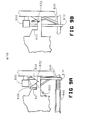
- FIG 7A and FIG 7B illustrate the mechanism employed to drive the sheet feeder.
- FIG 7A illustrates the sheet feeder drive mechanism in the normal operating position for the printer. In the normal operating position, the gear 158 is disengaged from the sheet feeder. There are two aspects to keeping the sheet feeder disengaged. First, the drive gear 156 has a flat portion on the outside hub 161 of the gear This flat portion has a corresponding rib 160 in the subframe 111.
- gear 156 When the drive gear 156 is in the disengaged position, the spring 155 holds the flat portion of the gear 156 against the rib 160 so the gear 156 does not move. Second, in order to insure that the gear does not interfere with the operation of the gear 158 during the normal operation of the printer, a cutout 157 in gear 156 is positioned across from the gear 158. The idler gear 158 drives the output feeder at all times.
- FIG 7B illustrates the printer with the sheet feeder engaged.
- the actuator 139 on carriage 131 is driven past the bail lift position and against the clutch arm 150.
- the clutch arm 150 slides the gear 156 over until the gear 156 is aligned with gear 158 and the hub 161 is clear of rib 160.
- the platen drive motor is then activated and the platen begins to rotate which in turn drives the cut sheet feeder with its D shaped wheels 154.
- the cut sheet of paper is then fed into the printer as described above.
- the clutch arm 150 is no longer required and the carriage may be moved to the home position.
- the cut sheet feeder assembly will then continue to rotate until the flat portion of hub 161 again aligns with the rib 160 and the gear slides over into the disengaged position shown in FIG 7A.
- FIG 5 is a side view of the present invention having continuous forms loaded.
- the continuous forms 500 are fed from the bottom of the printer up through sprockets 320, underneath sheet metal guide 220 and around the platen 120, then under bail 140 and out the top of the printer.
- a tear off bar is provided on the case of the printer to aid in the separation of one form from the next form.
- a top of form position is established by counting the number of revolutions of the platen drive motor after the forms have passed the paper sensor.
- the first printable line is defined as one-sixth inch below the physical top of the form.
- a novel feature of the preferred embodiment of the present invention is the printer's ability to load and unload the continuous forms.
- the user or the user's computer system may select either hand or tray fed cut sheets of paper be used.
- the printer retracts the continuous form paper from the platen employing the continuous form drive.
- the continuous forms are retracted until the continuous forms are out of the paper path for cut sheets of paper.
- the printer then disengages the continuous form drive as described below.
- the printer clears the paper path of any cut sheets of paper.
- the printer re-engages the continuous form feed and advances the forms into the printer where paper guides 220 and frame member 240 direct the forms against the platen.
- the forms trip the paper sensor as described above and the forms are positioned in front of the print head. Again, the printer controller counts the revolutions of the platen drive motor since the paper passed the paper sensor to determine the position of the paper and the top of form.
- FIG 9A and FIG 9B illustrate the clutch mechanism employed to engage and disengage the continuous form feeder.
- the sprocket drive gear 810 is disengaged from the hub 800 and the platen is free to operate independently of the continuous form feeder.
- the sprocket drive gear 810 is engaged with the hub 800 and both the sprockets 320 and the platen 120 are driven by the platen motor 125.
- the sprocket drive gear 810 is moved from the disengaged state to the engage state by clutch arm 820.
- the clutch arm is in turn driven by actuator 128 mounted to the carriage 131.
- the clutch arm operates in slot 830.
- the slot has two resting positions 831 and 832 for the clutch arm 820.
- the sprocket drive gear In the first position 831, the sprocket drive gear is disengaged from the drive hub. In the second position 832, the sprocket drive gear is engaging the drive hub.
- the actuator engages the clutch arm 820 just past the last printing position.
- the clutch arm is moved from the first position to the second position by the actuator sliding the arm along the bottom of the slot 830 to position 832.
- Spring 840 latches the clutch arm into position 832 by pulling and holding the arm into the notch.
- the actuator pushes the clutch arm up the ramp 834. This causes the clutch arm to ride over the top of the actuator 128 and then snap back to the end of slot 830.
- the clutch arm slides into the first position 831. In this way the carriage may be used to engage and disengage the continuous paper feed.
Landscapes
- Handling Of Sheets (AREA)
- Handling Of Cut Paper (AREA)
Abstract
Description
- This invention relates to the field of printing and more particularly to a simplified mechanism for positioning and moving paper through a serial character printer. In particular, this mechanism is capable of accepting continuous forms and hand and paper tray fed cut sheets of paper alternatively without having to unload and reload the printer.
- Printers may be classified by the rate and technique used to print on the paper. Of particular interest due to their low cost to both acquire and operate are serial character printers. These printers typically print a single character at a time using an impact, usually a dot matrix impact, ink jet or thermal technique.
- These printers have two key subsystems, the paper feed subsystem and the printing mechanism. The essential aspect of such printers being their low cost, attention must be paid to the cost of each subsystem.
- Low cost paper feed systems have been developed in the past. However, these prior art systems tend to be optimized for one type of paper, either hand fed sheet or continuous forms. Although these systems may be adapted to accept another type of paper, the adapted paper feed system operates with less than optimum performance.
- These prior art paper feed systems add motors and solenoids to perform the movement required to handle the new type of paper. Additional motors and solenoids drive up the cost of the printer. Also, they usually require the user to remove and reload the paper each time the type of paper is changed. They also increase the maintenance required to keep the printer operating .
- According to a first aspect of the present invention there is provided a printer for printing on individually or continuously fed sheets comprising a frame, a platen mounted on the frame, sheet guides attached to the frame, a sheet sensor attached to the frame, a carriage having a print head, carriage drive means for movably mounting the carriage in the printer and moving the print head parallel to the platen from a starting to an ending print position, and platen drive means mounted on the frame and coupled to the platen for advancing a fed sheet around the platen, characterised in that there are also provided one or more further printer component means with respective printer component operating means, and control means for controlling the carriage drive means, the printer component operating means and the platen drive means, the control means being responsive to the sheet sensor.
- An advantage of the invention is that it provides a low cost and very reliable paper feed system. Furthermore it accepts and reliably handles a variety of paper, including cut sheets and continuous forms, without adding solenoids or expensive motors. The cut sheets may be hand- or automatically fed. Moreover it permits the type of paper being used in the printer to be changed without the user having to unload the current paper and load the new type of paper. A single paper sensor is employed for detecting paper fed from any paper path.
- According to a second aspect of the present invention there is provided a sheet sensor for a printer for detecting the presence of a sheet fed from a first or second sheet path, the sensor comprising frame in 5 close proximity to both sheet paths an arm mounted on the frame and having a first and second portions, the arm being pivotally mounted about a point located between the first and second portions, with the first portion being in the first path and the second portion being in the second sheet path, and an optical detector mounted on the frame and being responsive to the arm.
- A preferred embodiment of the present invention will now be described, by way of example only, with reference to the accompanying drawings, of which:
- FIG 1 is a top view of the preferred embodiment of the present invention
- FIG 2 is a side view of the preferred embodiment of the present invention
- FIG 3 is a side view of the preferred embodiment of the present invention illustrating a single cut sheet of paper loaded by hand.
- FIG 4A and FIG 4B illustrate the operation of the bail lift mechanism.
- FIG 5 is a side view of the preferred embodiment of the present invention illustrating a continuous form loaded.
- FIG 6 is a side view of the preferred embodiment of the present invention illustrating a single cut sheet loaded from a paper tray containing cut sheets of paper.
- FIG 7A and FIG 7B illustrate the clutch mechanism employed to drive the sheet feeder.
- FIG 8 is a front view of the preferred embodiment of the present invention.
- FIG 9A and FIG 9B illustrate the clutch mechanism employed to engage and disengage the continuous paper feeder.
- FIG 10A, FIG 10B and FIG 10C illustrate a paper sensor employed in the preferred embodiment of the present invention.
- FIG 1 is a top view of the preferred embodiment of the present invention. FIG 2 is a side view of the preferred embodiment of the present invention. FIG 8 is a front view of the preferred embodiment of the present invention. The
printer 100 comprises aframe 110, a platen assembly, a carriage assembly, a continuous form feeder assembly, an optional cut sheet feeder assembly and a printer controller. The paper feed path is selected by the user through a printer control panel or the user's computer system through a communications interface. - The
printer frame 110, and indeed most of the printer parts, are made from injection molded plastic. - The platen assembly accepts paper from one of three paper feed paths and precisely positions the paper to permit the carriage assembly to print on the paper. This printer accepts single cut sheets of paper fed from a paper tray, single cut sheets of paper feed by hand, and continuous forms.
- The carriage assembly which mounts in
frame 110 holds and positions the print head used to print the characters on the paper. Any type of print head, thermal, impact, or ink jet may be used with the present invention. In the preferred embodiment of the present invention, a dot matrix impact type print head having 24 print wires is employed. The carriage assembly also serves to select the paper path which will be used to feed paper into the platen assembly and to control the bail and other parts of the printer. By using the carriage to control the operation of the platen assembly, solenoids and expensive motors have been eliminated thereby reducing the cost and improving the reliability of the printer. - The continuous form feeder assembly accepts and holds continuous forms and transfers those forms to the platen assembly when the user or the user's computer system selects continuous forms.
- The cut sheet feeder assembly accepts and holds cut sheets of paper in a paper tray and transfers one sheet of paper at a time to the platen when the tray feed is selected.
- The platen assembly comprises the
platen 120, abail 140,pinch rollers 600 andpaper guides platen 120 has agear platen 120. Two ribbedspacers 123 are molded withgears spacers 123 are used to center theplaten 120 inframe 110. The platen is mounted in a manner which permits it to rotate freely. The platen is rotated by theplaten motor 125 through agear hub 800.Pinch rollers 600 are employed to guide the paper around the platen. Twopaper guides paper guide 112 is used to guide single sheets, either fed from a paper tray or by hand, around the bottom of the platen. Continuous forms are directed up from the bottom of the printer as described below. Thepaper guide 220 holds paper against the platen as the paper approaches theprint head 130. Athird paper guide 230, attached to the carriage assembly insures that the paper will not catch on the bottom of the print head and jam The paper then passes under abail 140. - The
bail 140 is made of steel and hasrollers 141 which permit the paper to move smoothly between the bail and theplaten 120. The bail is mounted in theframe 110 and has a first and second position. Thebail 140 is biased into the first position by aspring 240. In the first position the bail is resting against theplaten 120. Thebail 140 keeps the paper flat against theplaten 120 while the printer is printing. In the second position thebail 140 is held away from the platen by a distance which permits paper to be load into the printer. This distance must be sufficient to insure that the paper always passes between thebail 140 and theplaten 120. The bail is bent atpoint 146 to prevent the bail from hitting the print head when the print head is in the home position and the bail is in the second position. - The carriage assembly comprises the
print head 130, acarriage 131, carriage guides 132 and 137, and a carriage drive subsystem. The print head is firmly mounted to thecarriage 131. The carriage mounts on the carriage guides 132 and 137 which are attached to theframe 110. The carriage moves parallel to theplaten 120 on the steel guides 132 and 137. Thecarriage 131 has twonovel actuators Actuator 139 has a flat tip and anangled section 145. The angled section is at approximately 33 degrees from the flat tip. Theactuator 128 has a flat tip and a smooth top. The operation of the actuators will be described below. - The carriage drive subsystem comprises a
motor 135,hubs belt 133. The belt is driven by ahub 134 attached to themotor 135. The other end of the belt is supported byhub 136 and kept under tension by a wedge andspring mechanism 210. - The continuous form feeder assembly comprises two
sprockets 320,drive shaft 840,drive gear 810 and a clutch assembly. Thesprockets 320 have covers, not shown, which hold the continuous forms against thesprockets 320. The sprockets are mounted on thesquare drive shaft 840 which may be driven through asprocket drive gear 810. Thesprocket drive gear 810 has a first and second position. In first position the continuous form assembly is driven by theplaten motor 125 throughhub 800. In the second position the continuous form assembly is disengaged from theplaten motor 125. Thedrive gear 810 is biased into the second position by aspring 870 Thedrive gear 810 is moved from the second position to the first position by the clutch assembly. The clutch assembly comprises aclutch arm 820 and aspring 860. One end of theclutch arm 820 has a Y shape which contacts drivegear 810. The other end of theclutch arm 820 rests inslot 830 of theframe 110 and is held in the slot by thespring 860. The spring is shown in FIG 9A. - A cut sheet feeder assembly comprises
subframe 111, a cutsheet paper tray 114,idler gear 158, a sheet feeder, and an output feeder. The subframe attaches to theframe 110. Theidler gear 158 is rotatably mounted to thesubframe 111. The paper try 114 mounts in aprinter tray support 113 molded into theframe 110. The sheet feeder comprises adrive rod 151 which is mounted in a bearing insubframe 111, twowheels 154 and a clutch assembly. The clutch assembly comprise agear 156, aspring 155 and aclutch arm 150. Thedrive rod 151 is driven bygear 156 which is held against thesubframe 111 byspring 155. Thegear 156 is driven by theplaten drive motor 125 throughgear 158 and theplaten gear 121. Two D shapedrubber wheels 154 are mounted to thedrive rod 151. The rubber wheels are positioned so that they make contact with the top sheet of paper in thepaper feeder tray 114. Aclutch arm 150 having a Y shaped end rests against thegear 156 and passes through a hole in theframe 110. The clutch arm is mounted on a pivot which is attached to thesubframe 111. The output feeder comprises adrive rod 152 which is mounted in a bearing insubframe 111. Thedrive rod 152 is driven bygear 159 throughgear 158 andplaten gear 121 from theplaten drive motor 125. Tworubber wheels 153 are mounted to thedrive rod 152 and assist the paper as it moves off theplaten 120 into an output tray which is a shelf in the case of the printer. - The cut sheet feeder is optional and may be removed by disconnecting
subframe 111 fromframe 110 and removing thepaper tray 114. This permits even a further reduction in cost if desired. - FIG 10A, FIG 10B and FIG 10C describe a paper sensor employed in the preferred embodiment of the present invention. The
paper sensor 700 comprises adetector arm 701 pivotally mounted below theplaten 120 in a slot in thestructural frame member 240. Thearm 701 swings freely and, at the end of its travel, breaks a light beam inoptical detector 702. The paper sensor is capable of detecting either cut sheets of paper fed from the back of the printer, or continuous forms fed from underneath the printer. FIG 10A illustrates thepaper sensor 700 without any paper present. Thearm 701 swings down beneath the light beam of theoptical detector 702. In this position, thearm 701 comes into close proximity, but does not touch, theplaten 120. FIG 10B illustrates thepaper sensor 700 with a cut sheet ofpaper 500 present. The cut sheet of paper strikes the top 710 ofarm 701 as it curls away from theplaten 120. Thearm 701 breaks the light beam in the optical detector indicating paper is present. FIG 10C illustrates thepaper sensor 700 with continuous forms. Thecontinuous forms 500 are fed from the bottom of the printer through the sprockets 310 and up toward theplaten 120. As the paper passespoint 711 on thearm 701, the arm is pushed down and breaks the light beam in the optical detector. In this manner, one paper sensor is capable of detecting paper coming from any paper path. - The printer operates as follows, depending on the type of paper selected. The preferred embodiment of the present invention accepts cut sheets of paper fed either by hand or from a paper tray and continuous forms alternately under the control of the printer controller as selected by the user or the user's computer system.
- Often in office operations it is extremely useful to be able to load a single sheet of paper, usually letterhead stationary, into the printer. FIG 3 is a side view of the present invention having a single cut sheet of paper loaded by hand. In the preferred embodiment of the present invention, a single sheet of paper may be loaded by placing the sheet of paper through a slot of the printer case (not shown) between an
alignment tray 410 and theoutput tray 420 until it strikes theplaten 120. The user then presses a line feed switch on the printer control panel which causes the platen to begin to rotate. The sheet of paper then trips the paper sensor. Once thepaper 500 is detected, the printer automatically loads the sheet of paper. The first step in loading the paper is to position the paper around theplaten 120. The printer controller continues rotating the platen and thereby feeding the paper between theplaten 120 and theframe member 240, underneathguide 220 and around to immediately in front of theprint head 130. The top printable line of the paper, approximately one-sixth of an inch below the top of the paper, is aligned beneath theprint head 130 and the printer begins printing. The exact position of the paper is determined by the printer controller from when the paper passed the paper sensor and the number of revolutions of theplaten drive motor 125. Depending on the size and spacing of the printer font selected, the printer will be able to print approximately four lines before the top of the paper runs up against thebail 140. The next step is to lift the bail. - FIG 4A and FIG 4B illustrate the operation of the bail lift mechanism. FIG. 4A shows the
actuator 139 located on thecarriage 131 with thecarriage 131 in the home position. In this position, theprint head 130 is aligned with the first printable column on the paper. This position is referred to as the home position. To lift the bail, the carriage motor moves thecarriage 131 past the home thereby driving the wedge portion against the side ofbail 140 and forcing the bail away from theplaten 120. This does not affect the printing operation of the printer since the printer will not need to print left of the first printable column on the paper. FIG 4B illustrates the liftedbail 140. - The bail lift procedure is as follows: the printer backs the paper down approximately four lines, lifts the bail as described above, and advances the paper approximately five lines. The bail is then released by moving the
carriage 131 back to the home position thereby moving theactuator 139 away from the bail and allowing thespring 240 to move the bail back against theplaten 120. - The printer then continues to print on the paper until the last printable line of the printer is reached. The last printable line is defined to be approximately one-quarter inch from the bottom of the sheet of paper. The single sheet of paper is then moved into the output tray of the printer using the platen drive motor to rotate the paper around the
platen 120 until it is free of theplaten 140 and helped into the output tray by the output feeder. - Although occasionally hand feeding a sheet of stationary is acceptable, more often office operations will use cut sheets of paper, for example, a large mailing of form letters. In these situations, it would be convenient to feed cut sheets of paper automatically. In the preferred embodiment of the present invention, cut sheets of paper may be loaded into the
paper tray 114 and then installed in the printer inpaper tray support 113. The paper tray employed in the preferred embodiment of the present invention is compatible with paper trays commonly used in low cost photocopiers. These paper trays comprise a plastic tray havingpaper separators 115, usually made of stamped sheet metal. The cut sheets of paper are typically held against thepaper separators 115 by a steel spring. The paper separators typically have triangularly shaped ends which are designed to separate the top sheet of paper from the remaining sheets of paper in the paper feed tray when the top sheet is pushed parallel to the paper feed tray. - The preferred embodiment of the present invention employs a novel means for supplying the force required to separate a single sheet of paper away from the paper tray and feed that sheet of paper into the printer. FIG 6 is a side view of the present invention illustrating a single cut sheet of
paper 500 being loaded from a paper tray containing cut sheets of paper. As shown in FIG 2, the D shaped rubber wheels are normally held in a position with the flat portions of the wheels parallel to thetray 114. This permits thetray 114 to be easily inserted and removed from the printer. When a cut sheet is to be fed from thetray 114, thewheels 154 are rotated until the front portion of the wheel comes into contact with the cut sheets of paper held in the paper tray. As thewheels 154 continue to rotate the top sheet ofpaper 500 begins to buckle, as shown in FIG 6, separating itself from the remaining stack of paper in thepaper tray 114. As thewheel 154 continues to rotate, the top sheet ofpaper 500 will spring around thepaper separators 115 and feed along thepaper guide 112. Thepaper 500 finally is driven between theguide 112 and theplaten 120. Thepaper 500 is driven by thewheels 154 approximately twenty percent faster than theplaten 120 accepts thepaper 500. This insures that the paper will feed squarely into the platen and not at an angle which would cause the paper to be misaligned with the printer. Once thepaper 500 has made firm contact with theplaten 120, the platen begins to move the paper. This is designed to correspond to approximately the time that the trailing edge of the D shapedwheels 154 lifts off thepaper 500. The paper is then free fromwheels 154 and theplaten 120 draws the paper into the platen assembly. Operation from this point is identical to the operation with the hand fed sheet of paper. Theplaten drive motor 125 is used to rotate the platen and thereby feed the paper underguide 112, between theplaten 120 and theframe member 240, underneathguide 220 and around to immediately in front of theprint head 130. The top printable portion of the paper is aligned beneath theprint head 130 and the printer begins printing. The exact position of the paper is determined by the printer controller from when the paper passed the paper sensor and the number of revolutions of theplaten drive motor 125. Depending on the size and spacing of the print font selected, the printer will be able to print approximately four lines before the top of the paper runs up against thebail 140. The next step is to lift the bail. - The bail lift procedure is as follows: the printer backs the paper down approximately four lines, lifts the bail as described above, advances the paper approximately five lines and releases the bail.
- The printer then continues to print on the sheet of paper until the last printable line of the printer is reached. The single sheet of paper is then moved into the output tray of the printer and the next cut sheet of paper is loaded.
- Since one object of this invention is low cost, a low cost means of driving the sheet feeder is required. The preferred embodiment of the present invention feeds cut sheets of paper without employing separate drive motors or solenoids. FIG 7A and FIG 7B illustrate the mechanism employed to drive the sheet feeder. FIG 7A illustrates the sheet feeder drive mechanism in the normal operating position for the printer. In the normal operating position, the
gear 158 is disengaged from the sheet feeder. There are two aspects to keeping the sheet feeder disengaged. First, thedrive gear 156 has a flat portion on theoutside hub 161 of the gear This flat portion has acorresponding rib 160 in thesubframe 111. When thedrive gear 156 is in the disengaged position, thespring 155 holds the flat portion of thegear 156 against therib 160 so thegear 156 does not move. Second, in order to insure that the gear does not interfere with the operation of thegear 158 during the normal operation of the printer, acutout 157 ingear 156 is positioned across from thegear 158. Theidler gear 158 drives the output feeder at all times. - FIG 7B illustrates the printer with the sheet feeder engaged. When it is time to load a sheet of paper from the
paper tray 114, theactuator 139 oncarriage 131 is driven past the bail lift position and against theclutch arm 150. Theclutch arm 150 slides thegear 156 over until thegear 156 is aligned withgear 158 and thehub 161 is clear ofrib 160. The platen drive motor is then activated and the platen begins to rotate which in turn drives the cut sheet feeder with its D shapedwheels 154. The cut sheet of paper is then fed into the printer as described above. Once thegear 156 has rotated past thecutout 157, theclutch arm 150 is no longer required and the carriage may be moved to the home position. The cut sheet feeder assembly will then continue to rotate until the flat portion ofhub 161 again aligns with therib 160 and the gear slides over into the disengaged position shown in FIG 7A. - Office operations also often employ continuous printed forms, for example invoices or order forms, in their daily operations. FIG 5 is a side view of the present invention having continuous forms loaded. The
continuous forms 500 are fed from the bottom of the printer up throughsprockets 320, underneathsheet metal guide 220 and around theplaten 120, then underbail 140 and out the top of the printer. A tear off bar is provided on the case of the printer to aid in the separation of one form from the next form. A top of form position is established by counting the number of revolutions of the platen drive motor after the forms have passed the paper sensor. The first printable line is defined as one-sixth inch below the physical top of the form. - A novel feature of the preferred embodiment of the present invention is the printer's ability to load and unload the continuous forms. Once the printer has been printing on continuous form paper, the user or the user's computer system may select either hand or tray fed cut sheets of paper be used. The printer retracts the continuous form paper from the platen employing the continuous form drive. The continuous forms are retracted until the continuous forms are out of the paper path for cut sheets of paper. The printer then disengages the continuous form drive as described below. When the user or user's computer again wishes to use the forms, the printer clears the paper path of any cut sheets of paper. The printer re-engages the continuous form feed and advances the forms into the printer where paper guides 220 and
frame member 240 direct the forms against the platen. The forms trip the paper sensor as described above and the forms are positioned in front of the print head. Again, the printer controller counts the revolutions of the platen drive motor since the paper passed the paper sensor to determine the position of the paper and the top of form. - FIG 9A and FIG 9B illustrate the clutch mechanism employed to engage and disengage the continuous form feeder. In FIG 9A the
sprocket drive gear 810 is disengaged from thehub 800 and the platen is free to operate independently of the continuous form feeder. In FIG 9B thesprocket drive gear 810 is engaged with thehub 800 and both thesprockets 320 and theplaten 120 are driven by theplaten motor 125. Thesprocket drive gear 810 is moved from the disengaged state to the engage state byclutch arm 820. The clutch arm is in turn driven byactuator 128 mounted to thecarriage 131. The clutch arm operates inslot 830. The slot has two restingpositions clutch arm 820. In thefirst position 831, the sprocket drive gear is disengaged from the drive hub. In thesecond position 832, the sprocket drive gear is engaging the drive hub. The actuator engages theclutch arm 820 just past the last printing position. The clutch arm is moved from the first position to the second position by the actuator sliding the arm along the bottom of theslot 830 toposition 832.Spring 840 latches the clutch arm intoposition 832 by pulling and holding the arm into the notch. To move from thesecond position 832 to the first position, the actuator pushes the clutch arm up theramp 834. This causes the clutch arm to ride over the top of theactuator 128 and then snap back to the end ofslot 830. When the carriage returns to a printing position, the clutch arm slides into thefirst position 831. In this way the carriage may be used to engage and disengage the continuous paper feed. - Additional application of the present invention are readily apparent to those skilled in the art.
Claims (10)
Priority Applications (1)
| Application Number | Priority Date | Filing Date | Title |
|---|---|---|---|
| EP94116772A EP0644054B1 (en) | 1987-05-29 | 1988-05-27 | Printer |
Applications Claiming Priority (2)
| Application Number | Priority Date | Filing Date | Title |
|---|---|---|---|
| US07/056,094 US4808019A (en) | 1987-05-29 | 1987-05-29 | Unified paper path printer |
| US56094 | 1987-05-29 |
Related Child Applications (1)
| Application Number | Title | Priority Date | Filing Date |
|---|---|---|---|
| EP94116772.8 Division-Into | 1994-10-25 |
Publications (3)
| Publication Number | Publication Date |
|---|---|
| EP0293243A2 true EP0293243A2 (en) | 1988-11-30 |
| EP0293243A3 EP0293243A3 (en) | 1990-09-19 |
| EP0293243B1 EP0293243B1 (en) | 1995-07-12 |
Family
ID=22002109
Family Applications (2)
| Application Number | Title | Priority Date | Filing Date |
|---|---|---|---|
| EP94116772A Expired - Lifetime EP0644054B1 (en) | 1987-05-29 | 1988-05-27 | Printer |
| EP88304857A Expired - Lifetime EP0293243B1 (en) | 1987-05-29 | 1988-05-27 | Printer |
Family Applications Before (1)
| Application Number | Title | Priority Date | Filing Date |
|---|---|---|---|
| EP94116772A Expired - Lifetime EP0644054B1 (en) | 1987-05-29 | 1988-05-27 | Printer |
Country Status (6)
| Country | Link |
|---|---|
| US (1) | US4808019A (en) |
| EP (2) | EP0644054B1 (en) |
| JP (1) | JP2752372B2 (en) |
| CA (1) | CA1288281C (en) |
| DE (2) | DE3854140T2 (en) |
| HK (1) | HK183195A (en) |
Cited By (1)
| Publication number | Priority date | Publication date | Assignee | Title |
|---|---|---|---|---|
| EP0508803A2 (en) * | 1991-04-11 | 1992-10-14 | Brother Kogyo Kabushiki Kaisha | Printer having continuous paper/cut paper changeover apparatus |
Families Citing this family (7)
| Publication number | Priority date | Publication date | Assignee | Title |
|---|---|---|---|---|
| US5135321A (en) * | 1987-05-29 | 1992-08-04 | Hewlett-Packard Company | Unified paper path printer with automatic parking feature |
| JP2638972B2 (en) * | 1988-08-16 | 1997-08-06 | ブラザー工業株式会社 | Printer |
| JPH0259378A (en) * | 1988-08-24 | 1990-02-28 | Brother Ind Ltd | Printer |
| DE3906611A1 (en) * | 1989-03-02 | 1990-09-06 | Philips Patentverwaltung | ARRANGEMENT FOR ADJUSTING A PRINTER |
| US5139355A (en) * | 1991-05-16 | 1992-08-18 | Printek, Inc. | Printer with multi-tractor form shuttle |
| US5217312A (en) * | 1992-05-19 | 1993-06-08 | Lexmark International, Inc. | Single lever push/pull/park selector for printer forms tractor |
| US5793177A (en) * | 1995-09-11 | 1998-08-11 | Hewlett-Packard Company | Adaptable media motor feed system for printing mechanisms |
Citations (6)
| Publication number | Priority date | Publication date | Assignee | Title |
|---|---|---|---|---|
| FR2567075A1 (en) * | 1984-07-06 | 1986-01-10 | Centronics Data Computer | PAPER DISPLACEMENT DEVICE FOR PRINTER |
| JPS6183074A (en) * | 1984-10-01 | 1986-04-26 | Canon Inc | Printer |
| GB2182142A (en) * | 1985-10-07 | 1987-05-07 | Seikosha Kk | Detector for detecting the passage of first and second material through respective guide paths |
| EP0223523A2 (en) * | 1985-11-09 | 1987-05-27 | Fujitsu Limited | Method and apparatus for operating a printer |
| DE3708601A1 (en) * | 1986-03-18 | 1987-10-01 | Canon Kk | Paper feed device for a recording apparatus |
| US4707159A (en) * | 1984-07-26 | 1987-11-17 | Canon Kabushiki Kaisha | Serial printer including a laterally reciprocable recording head, paper bail control, paper detection and feeding means, a multicolor ink ribbon including a head cleaning zone, a ribbon cassette and ribbon shift means |
Family Cites Families (10)
| Publication number | Priority date | Publication date | Assignee | Title |
|---|---|---|---|---|
| US4452543A (en) * | 1982-01-15 | 1984-06-05 | Florida Data Corporation | High speed printer with multiple paper paths |
| JPS59104971A (en) * | 1982-12-09 | 1984-06-18 | Canon Inc | Printer |
| US4581618A (en) * | 1983-03-09 | 1986-04-08 | Canon Kabushiki Kaisha | Recorder having paper feed mechanism |
| CH654256A5 (en) * | 1983-06-03 | 1986-02-14 | Hermes Precisa International | SHEET FEEDING DEVICE FOR PRINTER OR WRITING MACHINE. |
| JPS6021278A (en) * | 1983-07-15 | 1985-02-02 | Brother Ind Ltd | Paper bail apparatus of printer |
| JPS6044379A (en) * | 1983-08-19 | 1985-03-09 | Sanyo Electric Co Ltd | Printer |
| EP0173139A1 (en) * | 1984-08-31 | 1986-03-05 | Kabushiki Kaisha Toshiba | Printing apparatus |
| IT1196758B (en) * | 1984-11-19 | 1988-11-25 | Olivetti & Co Spa | PRINT SUPPORT FEEDER FOR A WRITING MACHINE OR SIMILAR OFFICE MACHINES |
| JPS6264579A (en) * | 1985-09-18 | 1987-03-23 | Fujitsu Ltd | Opening and closing mechanism for paper bail |
| JPS6280072A (en) * | 1985-10-04 | 1987-04-13 | Oki Electric Ind Co Ltd | Printer |
-
1987
- 1987-05-29 US US07/056,094 patent/US4808019A/en not_active Expired - Lifetime
-
1988
- 1988-03-04 CA CA000560617A patent/CA1288281C/en not_active Expired - Lifetime
- 1988-05-18 JP JP63121638A patent/JP2752372B2/en not_active Expired - Fee Related
- 1988-05-27 EP EP94116772A patent/EP0644054B1/en not_active Expired - Lifetime
- 1988-05-27 EP EP88304857A patent/EP0293243B1/en not_active Expired - Lifetime
- 1988-05-27 DE DE3854140T patent/DE3854140T2/en not_active Expired - Fee Related
- 1988-05-27 DE DE3856029T patent/DE3856029T2/en not_active Expired - Fee Related
-
1995
- 1995-11-30 HK HK183195A patent/HK183195A/en not_active IP Right Cessation
Patent Citations (6)
| Publication number | Priority date | Publication date | Assignee | Title |
|---|---|---|---|---|
| FR2567075A1 (en) * | 1984-07-06 | 1986-01-10 | Centronics Data Computer | PAPER DISPLACEMENT DEVICE FOR PRINTER |
| US4707159A (en) * | 1984-07-26 | 1987-11-17 | Canon Kabushiki Kaisha | Serial printer including a laterally reciprocable recording head, paper bail control, paper detection and feeding means, a multicolor ink ribbon including a head cleaning zone, a ribbon cassette and ribbon shift means |
| JPS6183074A (en) * | 1984-10-01 | 1986-04-26 | Canon Inc | Printer |
| GB2182142A (en) * | 1985-10-07 | 1987-05-07 | Seikosha Kk | Detector for detecting the passage of first and second material through respective guide paths |
| EP0223523A2 (en) * | 1985-11-09 | 1987-05-27 | Fujitsu Limited | Method and apparatus for operating a printer |
| DE3708601A1 (en) * | 1986-03-18 | 1987-10-01 | Canon Kk | Paper feed device for a recording apparatus |
Non-Patent Citations (1)
| Title |
|---|
| PATENT ABSTRACTS OF JAPAN, vol. 9, no.51 (M-361)(1774), March 6, 1985; JP-A-59 188 466 (EPUSON) 25.10.1984 * |
Cited By (2)
| Publication number | Priority date | Publication date | Assignee | Title |
|---|---|---|---|---|
| EP0508803A2 (en) * | 1991-04-11 | 1992-10-14 | Brother Kogyo Kabushiki Kaisha | Printer having continuous paper/cut paper changeover apparatus |
| EP0508803A3 (en) * | 1991-04-11 | 1993-03-24 | Brother Kogyo Kabushiki Kaisha | Printer having continuous paper/cut paper changeover apparatus |
Also Published As
| Publication number | Publication date |
|---|---|
| HK183195A (en) | 1995-12-08 |
| EP0644054B1 (en) | 1997-09-17 |
| EP0293243A3 (en) | 1990-09-19 |
| EP0293243B1 (en) | 1995-07-12 |
| DE3856029T2 (en) | 1998-01-15 |
| JP2752372B2 (en) | 1998-05-18 |
| JPH0236967A (en) | 1990-02-06 |
| DE3856029D1 (en) | 1997-10-23 |
| CA1288281C (en) | 1991-09-03 |
| DE3854140D1 (en) | 1995-08-17 |
| DE3854140T2 (en) | 1995-11-09 |
| EP0644054A1 (en) | 1995-03-22 |
| US4808019A (en) | 1989-02-28 |
Similar Documents
| Publication | Publication Date | Title |
|---|---|---|
| EP0549989B1 (en) | Paper supply mechanism in a printer | |
| US5730537A (en) | Print media handling and ejection system | |
| US5135321A (en) | Unified paper path printer with automatic parking feature | |
| US6007063A (en) | Paper output unit for ink-jet printer | |
| US6152631A (en) | Automatic paper sensing technique for an ink jet printer | |
| US5524994A (en) | Paper skew removal apparatus and a printer using the same | |
| EP0293243B1 (en) | Printer | |
| CA1139986A (en) | In-feed paper buckel control apparatus | |
| US6354586B1 (en) | Sheet feeder | |
| US4522519A (en) | Apparatus and process for drop-feeding sheets to a typing or printing machine including separable paper clamping trays | |
| US20060285909A1 (en) | Pinch plate lifting in a printer | |
| US6146036A (en) | Rotatable cam device for a pickup roller of a printer | |
| JP3208257B2 (en) | Printer paper feeder | |
| US6454476B1 (en) | Apparatus and method for picking and feeding print media sheets | |
| JP4835848B2 (en) | Recording medium feeding apparatus, recording apparatus, and liquid ejecting apparatus | |
| JPS60210475A (en) | Automatic cut sheet supplying and feeding device for printer | |
| US5183348A (en) | Printer having tractor unit attachable to one of upstream and downstream sides of platen | |
| GB2271556A (en) | Paper skew removal | |
| JP2710964B2 (en) | Paper feeder | |
| JP2519877B2 (en) | Paper feeder | |
| JPH05254672A (en) | Sheet feeding device and image formation device | |
| JPH07110720B2 (en) | Paper feeder | |
| JPS58193180A (en) | Automatic form inserter | |
| JP2009046232A (en) | Printer and paper feeding method | |
| JPH09267932A (en) | Paper supply device |
Legal Events
| Date | Code | Title | Description |
|---|---|---|---|
| PUAI | Public reference made under article 153(3) epc to a published international application that has entered the european phase |
Free format text: ORIGINAL CODE: 0009012 |
|
| AK | Designated contracting states |
Kind code of ref document: A2 Designated state(s): DE FR GB IT |
|
| PUAL | Search report despatched |
Free format text: ORIGINAL CODE: 0009013 |
|
| AK | Designated contracting states |
Kind code of ref document: A3 Designated state(s): DE FR GB IT |
|
| 17P | Request for examination filed |
Effective date: 19910201 |
|
| 17Q | First examination report despatched |
Effective date: 19921009 |
|
| GRAA | (expected) grant |
Free format text: ORIGINAL CODE: 0009210 |
|
| AK | Designated contracting states |
Kind code of ref document: B1 Designated state(s): DE FR GB IT |
|
| PG25 | Lapsed in a contracting state [announced via postgrant information from national office to epo] |
Ref country code: IT Free format text: LAPSE BECAUSE OF FAILURE TO SUBMIT A TRANSLATION OF THE DESCRIPTION OR TO PAY THE FEE WITHIN THE PRE;WARNING: LAPSES OF ITALIAN PATENTS WITH EFFECTIVE DATE BEFORE 2007 MAY HAVE OCCURRED AT ANY TIME BEFORE 2007. THE CORRECT EFFECTIVE DATE MAY BE DIFFERENT FROM THE ONE RECORDED.SCRIBED TIME-LIMIT Effective date: 19950712 Ref country code: FR Effective date: 19950712 |
|
| XX | Miscellaneous (additional remarks) |
Free format text: TEILANMELDUNG 94116772.8 EINGEREICHT AM 27/05/88. |
|
| REF | Corresponds to: |
Ref document number: 3854140 Country of ref document: DE Date of ref document: 19950817 |
|
| EN | Fr: translation not filed | ||
| PLBE | No opposition filed within time limit |
Free format text: ORIGINAL CODE: 0009261 |
|
| STAA | Information on the status of an ep patent application or granted ep patent |
Free format text: STATUS: NO OPPOSITION FILED WITHIN TIME LIMIT |
|
| 26N | No opposition filed | ||
| PGFP | Annual fee paid to national office [announced via postgrant information from national office to epo] |
Ref country code: GB Payment date: 19970425 Year of fee payment: 10 |
|
| PGFP | Annual fee paid to national office [announced via postgrant information from national office to epo] |
Ref country code: DE Payment date: 19970428 Year of fee payment: 10 |
|
| PG25 | Lapsed in a contracting state [announced via postgrant information from national office to epo] |
Ref country code: GB Free format text: LAPSE BECAUSE OF NON-PAYMENT OF DUE FEES Effective date: 19980527 |
|
| GBPC | Gb: european patent ceased through non-payment of renewal fee |
Effective date: 19980527 |
|
| PG25 | Lapsed in a contracting state [announced via postgrant information from national office to epo] |
Ref country code: DE Free format text: LAPSE BECAUSE OF NON-PAYMENT OF DUE FEES Effective date: 19990302 |